ISIS between Nokia (Alcatel-Lucent) SR and Cisco IOS XR
Anton Karneliuk
Hello my friend,
With this article we finish review of interior gateway protocols (IGP). Actually these two protocols: OSPF (including OSPFv3) and ISIS are two the most popular protocols in the world due their functionality and interoperability between vendors (like Nokia (Alcatel-Lucent) and SR OS) as both of them are standard-based. In my opinion, ISIS is even more powerful and scalable than OSPF and it supports natively IPv4 and IPv6 (and has option to support whatever else).
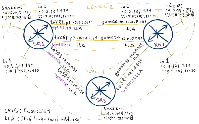
The only difference is that we have only three routers in the logical topology as well, because Cisco IOS XR doesn’t support ISIS in the VRF; so we can’t use VRF-lite and have to limit our lab only to these three routers. Well, in any case it’s better than two, so I’m sure we still can see many interesting things. Also point out that we are configuring ISIS simultaneously for IPv4 and IPv6, so pay attention to the addressing (especially IPv6 addressing, as we don’t configure IPv6 global unicast addresses at links between routers, just as we did it in OSPFv3 lab):
Take a look at system interface at SR1 and loopback 0 at XR1. These interfaces are “level-1-2” interfaces meaning that they are natively added into link state databases (LSDB) at both levels. All other interfaces are assigned either to level-1 or level-2.
Pay attention that at Nokia (Alcatel-Lucent) SR OS routers we have activated equal cost multipath (ECMP) with 2 allowed pathes.
Basic connectivity
I hope that you know main ISIS theory and know how it operates as I won’t provide too much theory.
There are many similarities between ISIS and OSPF/OSPFv3 as you know. The main fact is that both protocols are hierarchical. OSPF has a dedicated backbone that is area 0.0.0.0, and ISIS has level-2 that is backbone as well. Level-1 interfaces has the same sense as OSPF totally NSSA areas. It means that inside level-1 area only level-1 prefixes are propagated (redistributed in this area), whereas in level-2 area both level-1 and level-2 prefixes are distributed. ABRs (in ISIS terminology it’s called L1L2 router) include in their LSP dedicated A-bit “attached”, meaning that they are connected to backbone, if they have neighbors in other areas. When level-1 router sees that bit in LSP, it installs default route in direction of this L1L2 router, what looks very similar to LSA3 with default route generated by ABR in OSPF into stub/totally stub or totally NSSA areas.
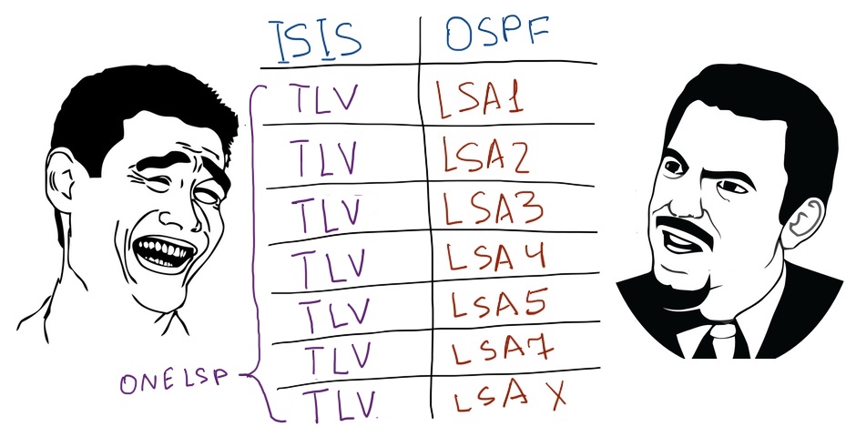
And I’d say that there are more similarities between ISIS and OSPFv3 then OSPFv2. The reason for this statement is that ISIS has strong separation between topology and prefixes (IPv4/IPv6 addresses). The metric is associated with neighbor as node and such node is identified by NET, which is full identifier of node including router-id and area-id. On top of build topology the network prefixes are reviewed and routing table (RIB) is built. OSPFv3 behaves in the similar way, because LSA1 (which is used for SPF calculations) doesn’t contain information about network addresses any more. Actually LSAs are another good point for comparison, as ISIS doesn’t have different types of them. All information is distributed in LSPs (Link-state packets), which has the following structure: besides header it has numerous TLV (Type-Length-Value) entries, which can describe virtually everything. Now you can understand that I really like ISIS, so I propose to proceed with configuration.
As OSPF ISIS supports two types of interfaces, which are point-to-point and broadcast. The latter is used in case where there are more than two routers on the segment and generates additional entry in LSDB (it’s considered as pseudo-node meaning that all other routers in this segment think that they are attached with point-to-point links to this pseudo-node). Such type isn’t very popular, so we’ll configure only one link between SR1 and XR1 (toXR1_p2 <-> g0/0/0/0.11) with this type to show how it looks like. All others link will be point-to-point. But first of all, before configuring the whole topology, we’ll focus only at level-2:
Wide-metric is necessary for operation of MPLS traffic-engineering based on RSVP. We don’t discuss it in this article, but such configuration is usually highly desirable. Another its advantage is overcoming of limitations of low metric, which is only 6 bits, making possible values for interface cost only in range 1-63.
If you have configure logging for protocol isis to console, Nokia (Alcatel-Lucent) SR OS will tell you about new adjacency. If not, you can check it in default log stream 99. Cisco IOS XR by default informs you to the console:
A:SR1# show log log-id 99
39 2016/08/20 18:30:07.06 UTC WARNING: ISIS #2045 Base VR: 1 ISIS (0) Adjacency state
“Adjacency status changed to up for interface: toXR1_p2, for level: l2, LSP-id: 0100.0025.5002.00-00 ”
!
!
RP/0/0/CPU0:XR1#RP/0/0/CPU0:Jun 16 23:45:23.111 : isis[1010]: %ROUTING-ISIS-5-ADJCHANGE : Adjacency to SR1 (GigabitEthernet0/0/0/0.10) (L2) Up, New adjacency
RP/0/0/CPU0:Jun 16 23:45:23.891 : isis[1010]: %ROUTING-ISIS-5-ADJCHANGE : Adjacency to SR1 (GigabitEthernet0/0/0/0.11) (L2) Up, New adjacency
Everything seems to be OK, as log tells us that adjacency is Up. ISIS has much easier adjacency structure then OSPF: only 3 states (down, initializing, up) comparing to 7 in OSPF. Let’s check the routing table for both IPv4 and IPv6. At SR1 we should see IPv4 and IPv6 address of Loopback0 from XR1:
A:SR1# show router route-table protocol isis ipv4
============================================================================
Route Table (Router: Base)
============================================================================
Dest Prefix[Flags] Type Proto Age Pref
Next Hop[Interface Name] Metric
—————————————————————————-
10.0.255.2/32 Remote ISIS 00h12m18s 18
10.0.0.1 10
10.0.255.2/32 Remote ISIS 00h12m18s 18
10.0.0.3 10
—————————————————————————-
No. of Routes: 2
!
!
A:SR1# show router route-table protocol isis ipv6
============================================================================
IPv6 Route Table (Router: Base)
============================================================================
Dest Prefix[Flags] Type Proto Age Pref
Next Hop[Interface Name] Metric
—————————————————————————-
—————————————————————————-
No. of Routes: 0
As we have configured ECMP, IPv4 RIB is fully OK, but IPv6 doesn’t work. If something is wrong in routing table, it makes sense to check LSDB at SR1, which is Nokia (Alcatel-Lucent) VSR (SR7750):
A:SR1# show router isis database SR1.00-00 detail level 2
============================================================================
Router Base ISIS Instance 0 Database
============================================================================
Displaying Level 2 database
—————————————————————————-
LSP ID : SR1.00-00 Level : L2
Sequence : 0x1a Checksum : 0x381c Lifetime : 1166
Version : 1 Pkt Type : 20 Pkt Ver : 1
Attributes: L1L2 Max Area : 3
SysID Len : 6 Used Len : 178 Alloc Len : 1492
TLVs :
Area Addresses:
Area Address : (3) 49.0001
Supp Protocols:
Protocols : IPv4 Protocols : IPv6
IS-Hostname : SR1
Router ID : 10.0.255.1
I/F Addresses :
I/F Address : 10.0.0.0
I/F Address : 10.0.255.1
I/F Address : 10.0.0.2
I/F Addresses IPv6 :
IPv6 Address : fc00::10:0:255:1
TE IS Nbrs :
Nor : XR1.00
Default Metric : 10
Sub TLV Len : 12
IF Addr : 10.0.0.0
Nbr IP : 10.0.0.1
TE IS Nbrs :
Nbr : SR1.02
Default Metric : 10
Sub TLV Len : 6
IF Addr : 10.0.0.2
TE IP Reach :
Default Metric : 0
Control Info : , prefLen 32
Prefix : 10.0.255.1 IPv6 Reach: Metric : ( I ) 0 Prefix : fc00::10:0:255:1/128
Authentication:
Auth Type : MD5(54) (16 bytes)
Auth Info : f040d7c42f8cce922cd589180d2c5e13
Level (2) LSP Count : 1
============================================================================
!
!
A:SR1# show router isis database XR1.00-00 detail level 2
============================================================================
Router Base ISIS Instance 0 Database
============================================================================
Displaying Level 2 database
—————————————————————————-
LSP ID : XR1.00-00 Level : L2
Sequence : 0xd Checksum : 0x818e Lifetime : 602
Version : 1 Pkt Type : 20 Pkt Ver : 1
Attributes: L1L2 Max Area : 0
SysID Len : 6 Used Len : 154 Alloc Len : 154
TLVs :
Authentication:
Auth Type : MD5(54) (16 bytes)
Auth Info : abb7016ad7a41029e8be9ecedf6ce7db
Area Addresses:
Area Address : (3) 49.0001
Supp Protocols:
Protocols : IPv4 Protocols : IPv6 MT Topology: MT ID : 0 No Flags MT ID : 2 No Flags
IS-Hostname : XR1
I/F Addresses :
I/F Address : 10.0.255.2
I/F Addresses IPv6 :
IPv6 Address : fc00::10:0:255:2
TE IS Nbrs :
Nbr : SR1.00
Default Metric : 10
Sub TLV Len : 0
TE IS Nbrs :
Nbr : SR1.02
Default Metric : 10
Sub TLV Len : 0
TE IP Reach :
Default Metric : 0
Control Info : , prefLen 32
Prefix : 10.0.255.2 MT IPv6 Reach. : MT ID : 2 Metric : ( I ) 0 Prefix : fc00::10:0:255:2/128
Level (2) LSP Count : 1
============================================================================
Good story that we see that both routers see IPv6 prefixes in LSP of each other. But they are of different types: one is usual IPv6, whereas another is MT IPv6. So I had to google a little bit to figure out what is it and have found this doc, which explains that MT stands for multi-topology and it’s another way of ISIS operation in case of different routed protocols (like IPv4 and IPv6). For us it means that Cisco IOS XR operates in multi-topology mode by default and to make them common operation happen, we need change mode in Nokia (Alcatel-Lucent) SR OS. If we need it, we make it:
*A:SR1>config>router>isis# info
———————————————-
ipv6-routing mt
multi-topology
ipv6-unicast
exit
———————————————-
After applying this configuration we see changes in routing table:
A:SR1# show router route-table protocol isis ipv6
============================================================================
IPv6 Route Table (Router: Base)
============================================================================
Dest Prefix[Flags] Type Proto Age Pref
Next Hop[Interface Name] Metric
—————————————————————————-
fc00::10:0:255:2/128 Remote ISIS 00h00m41s 18
fe80::2:1001-“toXR1_p1” 10
fc00::10:0:255:2/128 Remote ISIS 00h00m41s 18
fe80::2:1101-“toXR1_p2” 10
—————————————————————————-
No. of Routes: 2
If you have accurately reviewed output of LSP at Cisco IOS XR, you could that LSP SR1.00-00 miss MT field just after NLPID. It means that SR1 was operating not in multi-topology mode. Now it has changed:
RP/0/0/CPU0:XR1#sh isis database SR1.00-00 level 2 verbose
IS-IS CORE (Level-2) Link State Database
LSPID LSP Seq Num LSP Checksum LSP Holdtime ATT/P/OL
SR1.00-00 0x0000001d 0xfd98 1071 0/0/0
Area Address: 49.0001
NLPID: 0xcc
NLPID: 0x8e
MT: Standard (IPv4 Unicast)
MT: IPv6 Unicast 0/0/0
Hostname: SR1
Router ID: 10.0.255.1
IP Address: 10.0.0.0
IP Address: 10.0.255.1
IP Address: 10.0.0.2
IPv6 Address: fc00::10:0:255:1
Metric: 10 IS-Extended XR1.00
Interface IP Address: 10.0.0.0
Neighbor IP Address: 10.0.0.1
Metric: 10 MT (IPv6 Unicast) IS-Extended XR1.00
Metric: 10 IS-Extended SR1.02
Interface IP Address: 10.0.0.2
Metric: 10 MT (IPv6 Unicast) IS-Extended SR1.02
Metric: 0 IP-Extended 10.0.255.1/32
Metric: 0 MT (IPv6 Unicast) IPv6 fc00::10:0:255:1/128
Auth: Algorithm HMAC-MD5, Length: 17
The routing table at Cisco IOS XR fully corresponds to the view, what we have already seen at our Nokia (Alcatel-Lucent) SR OS router:
RP/0/0/CPU0:XR1#show route ipv4 isis
i L2 10.0.255.1/32 [115/10] via 10.0.0.2, 00:37:52, GigabitEthernet0/0/0/0.11
. [115/10] via 10.0.0.0, 00:37:52, GigabitEthernet0/0/0/0.10
!
!
RP/0/0/CPU0:XR1#show route ipv6 isis
i L2 fc00::10:0:255:1/128
. [115/10] via fe80::1:1101, 00:05:35, GigabitEthernet0/0/0/0.11
. [115/10] via fe80::1:1001, 00:05:35, GigabitEthernet0/0/0/0.10
What I have forgotten to configure in the beginning is advertisement of Lo2 interface at both routers into level-2 (and only in level-2), so I do it now:
Nokia (Alcatel-Lucent) VSR (SR 7750)
Cisco IOS XR (ASR 9000)
SR1
XR1
*A:SR1>config>router>isis$ info
—————————–
interface “Lo2”
level-capability level-2
passive
no shutdown
exit
—————————–
As you can see the configuration of ISIS is relatively easy and it’s much easier than configuration of OSPF in dual stack (simultaneous operation of IPv4 and IPv6) environment.
Before we go further, let’s briefly take a look at interface, where we have configured broadcast media type. In ISIS there is a similar concept to OSPF’s DR/BDR. Here it’s called DIS (Designated Intermediate System). One router (based on higher priority or higher MAC address) sends on shared media separate LSP, which seems to be a separate node (pseudonode). All routers on this shared segment (including DIS itself) seem to have point-to-point link with this pseudonode:
In this case SR1.03-00 is LSP of pseudnode. You see that both our routers show in their LSP SR1.00 and XR1.00 connectivity with pseudonode SR1.03. Also point out that metric that is derived from interface presents only in SR1.00 and XR1.00 LSPs.
As I have already mentioned, in ISIS there is a separation between topology (links and nodes) and associated prefixes (IPv4 or IPv6). You can see the topology by separate command:
To establish L1 adjacency the routers must have the same area-id. To establish L2 adjacency it’s irrelevant, so routers can be in different areas. That’s why it’s said that in ISIS the border between areas is on link, not on routers. Therefore the border between levels is always on router. Don’t mess these two terms.
After we’ve made the configuration above, SR3 establishes adjacency with both SR1 and XR1:
A:SR3# show router isis adjacency
============================================================================
Router Base ISIS Instance 0 Adjacency
============================================================================
System ID Usage State Hold Interface MT-ID
—————————————————————————-
SR1 L1 Up 20 toSR1 0,2
XR1 L1 Up 24 toXR1 0,2
—————————————————————————-
Adjacencies : 2
============================================================================
You can notice that we have configured “level-capabilities” at SR3 not under interface level as we have done it at SR1, but at ISIS configuration level in overall. It means that this Nokia (Alcatel-Lucent) VSR (SR 7750) will operate solely in level-1 mode. In Cisco IOS XR such configuration would be the following:
RP/0/0/CPU0:XR1(config-isis)#show conf
router isis CORE is-type level-1
!
end
So in Cisco IOS XR there are two different commands: “is-type level-1” at ISIS configuration level and “circuit-type level-1” at ISIS interface configuration level.
Let’s check the routing table at SR1:
A:SR3# show router route-table protocol isis ipv4
============================================================================
Route Table (Router: Base)
============================================================================
Dest Prefix[Flags] Type Proto Age Pref
Next Hop[Interface Name] Metric
—————————————————————————-
10.0.255.1/32 Remote ISIS 00h25m12s 15
10.1.0.0 10
10.0.255.2/32 Remote ISIS 00h25m00s 15
10.1.0.3 10
10.1.101.0/24 Remote ISIS 00h25m12s 15
10.1.0.0 10
10.1.102.0/24 Remote ISIS 00h25m00s 15
10.1.0.3 10
—————————————————————————-
No. of Routes: 4
!
!
A:SR3# show router route-table protocol isis ipv6
============================================================================
IPv6 Route Table (Router: Base)
============================================================================
Dest Prefix[Flags] Type Proto Age Pref
Next Hop[Interface Name] Metric
—————————————————————————-
fc00::10:0:255:1/128 Remote ISIS 00h25m16s 15
fe80::1:1301-“toSR1” 10
fc00::10:0:255:2/128 Remote ISIS 00h25m04s 15
fe80::2:2301-“toXR1” 10
fc00::10:1:101:0/120 Remote ISIS 00h25m16s 15
fe80::1:1301-“toSR1” 10
fc00::10:1:102:0/120 Remote ISIS 00h25m04s 15
fe80::2:2301-“toXR1” 10
—————————————————————————-
No. of Routes: 4
You can see here Lo1 interfaces that are level-1 only and system/loopback0 interfaces that are level-1/2 together, but there are no level-2 prefixes. And to be honest it’s really good as it’s simplify building of seamless MPLS (unified MPLS) architecture in Service Provider network due to ease of provisioning of LSP (Label Switched Path in this meaning) between BGP next-hops. I’ll cover this topic much later if I manage to find server to build more powerful lab as 3 routers isn’t enough at all for showcases of seamless MPLS.
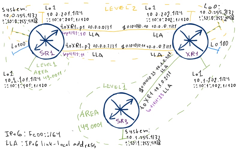
You can see that there is no default route, though previously I have told it must be. Well, as I’ve told before, it will be only if L1L2 router has peer in another area (comparing to its own). Let’s shutdown interface between SR1 and SR3 and change area-id at SR1 to 49.0011. Now we have the following domains:
Now condition of inter-area peering is achieved at XR1 and you see default routes:
A:SR3# show router route-table protocol isis ipv4
=============================================================================
Route Table (Router: Base)
============================================================================
Dest Prefix[Flags] Type Proto Age Pref
Next Hop[Interface Name] Metric
—————————————————————————-
0.0.0.0/0 Remote ISIS 00h04m11s 15
10.1.0.3 10
10.0.255.2/32 Remote ISIS 00h08m43s 15
10.1.0.3 10
10.1.102.0/24 Remote ISIS 00h08m43s 15
10.1.0.3 10
—————————————————————————-
No. of Routes: 3
!
!
A:SR3# show router route-table protocol isis ipv6
============================================================================
IPv6 Route Table (Router: Base)
============================================================================
Dest Prefix[Flags] Type Proto Age Pref
Next Hop[Interface Name] Metric
—————————————————————————-
::/0 Remote ISIS 00h04m14s 15
fe80::2:2301-“toXR1” 10
fc00::10:0:255:2/128 Remote ISIS 00h08m46s 15
fe80::2:2301-“toXR1” 10
fc00::10:1:102:0/120 Remote ISIS 00h08m46s 15
fe80::2:2301-“toXR1” 10
—————————————————————————-
No. of Routes: 3
You can also notice, that there is no level-1 routes from SR1 (i.E. 10.1.101.1/24). As we already told, level-1 prefixes are automatically injected into level-2 and propagated over it. But they aren’t injected into another level-1 area. Take a look at routing table at XR1:
RP/0/0/CPU0:XR1#show route ipv4 isis
i L2 10.0.201.0/24 [115/10] via 10.0.0.2, 00:10:24, GigabitEthernet0/0/0/0.11
. [115/10] via 10.0.0.0, 00:10:24, GigabitEthernet0/0/0/0.10
i L2 10.0.255.1/32 [115/10] via 10.0.0.2, 00:10:12, GigabitEthernet0/0/0/0.11
. [115/10] via 10.0.0.0, 00:10:12, GigabitEthernet0/0/0/0.10
i L2 10.1.101.0/24 [115/10] via 10.0.0.2, 00:10:12, GigabitEthernet0/0/0/0.11
. [115/10] via 10.0.0.0, 00:10:12, GigabitEthernet0/0/0/0.10
i L1 10.1.255.1/32 [115/10] via 10.1.0.2, 00:14:50, GigabitEthernet0/0/0/0.23
You can see that all prefixes associated with SR1 are L2 prefixes.
Nokia (Alcatel-Lucent) SR OS by default doesn’t show prefix type in routing table. You can check it issuing “show router isis routes”
We are still using changed topology. So we add to both Nokia (Alcatel-Lucent) SR1 and Cisco IOS XR1 a loopback 100 interface:
This interface has following addresses:
Interface
SR1
XR1
Loopback100
IPv4: 1.1.1.1/32
IPv6: 2001:1:1:1::1/128
IPv4: 11.11.11.11/32
IPv6: 2001:11:11:11::11/128
Let’s redistribute these routes into ISIS:
Nokia (Alcatel-Lucent) VSR (SR 7750)
Cisco IOS XR (ASR 9000)
SR1
XR1
*A:SR1>config>router>policy-options# info
—————————–
prefix-list “PL_IPV4_LOO100”
prefix 1.1.1.1/32 exact
exit
prefix-list “PL_IPV6_LOO100”
prefix 2001:1:1:1::1/128 exact
exit
policy-statement “RP_CONN_TO_ISIS”
entry 10
from
protocol direct
prefix-list “PL_IPV4_LOO100”
exit
to
protocol isis
exit
action accept
exit
exit
entry 20
from
protocol direct
prefix-list “PL_IPV6_LOO100”
exit
to
protocol isis
exit
action accept
exit
exit
exit
—————————–
A:SR1>config>router>isis# info
—————————–
export “RP_CONN_TO_ISIS”
—————————–
RP/0/0/CPU0:XR1(config)#show conf
route-policy RP_IPV4_LO100_TO_ISIS
if destination in (11.11.11.11/32) then
pass
endif
end-policy
!
route-policy RP_IPV6_LO100_TO_ISIS
if destination in (2001:11:11:11::11/128) then
pass
endif
end-policy
!
router isis CORE
address-family ipv4 unicast
redistribute connected level-1-2 route-policy RP_IPV4_LO100_TO_ISIS
!
address-family ipv6 unicast
redistribute connected level-1-2 route-policy RP_IPV6_LO100_TO_ISIS
!
!
end
Here it’s necessary to outline two differences difference in operation of ISIS in Nokia (Alcatel-Lucent) SR OS and Cisco IOS XR:
In Cisco XR you make redistribution under address family configuration, meaning that you have two different route-policies (one for IPv4 and another for IPv6) to make redistribution. In Nokia (Alcatel-Lucent) SR OS there is single policy both for IPv4 and IPv6.
By default Cisco redistributes routes only into level-2. You need explicitly add into configuration that you want also to include redistributed prefixes into level-1.
What is common between Nokia (Alcatel-Lucent) SR OS and Cisco IOS XR is that both of them redistribute routes as internal by default. So there is no difference between redistributed routes and routes announced by configuring interface. But this default behavior can be changes so that routes will be redistributed as external.
Now let’s check routing tables at our routers. SR1 has the following routes:
RP/0/0/CPU0:XR1#show route ipv4 isis
i L2 1.1.1.1/32 [115/10] via 10.0.0.2, 00:11:11, GigabitEthernet0/0/0/0.11
. [115/10] via 10.0.0.0, 00:11:11, GigabitEthernet0/0/0/0.10
i L2 10.0.201.0/24 [115/10] via 10.0.0.2, 02:02:40, GigabitEthernet0/0/0/0.11
. [115/10] via 10.0.0.0, 02:02:40, GigabitEthernet0/0/0/0.10
i L2 10.0.255.1/32 [115/10] via 10.0.0.2, 02:02:28, GigabitEthernet0/0/0/0.11
. [115/10] via 10.0.0.0, 02:02:28, GigabitEthernet0/0/0/0.10
i L2 10.1.101.0/24 [115/10] via 10.0.0.2, 02:02:28, GigabitEthernet0/0/0/0.11
. [115/10] via 10.0.0.0, 02:02:28, GigabitEthernet0/0/0/0.10
i L1 10.1.255.1/32 [115/10] via 10.1.0.2, 00:05:04, GigabitEthernet0/0/0/0.23
!
!
RP/0/0/CPU0:XR1#show route ipv6 isis
i L2 2001:1:1:1::1/128
. [115/10] via fe80::1:1101, 00:11:17, GigabitEthernet0/0/0/0.11
. [115/10] via fe80::1:1001, 00:11:17, GigabitEthernet0/0/0/0.10
i L2 fc00::10:0:201:0/120
. [115/10] via fe80::1:1101, 02:02:54, GigabitEthernet0/0/0/0.11
. [115/10] via fe80::1:1001, 02:02:54, GigabitEthernet0/0/0/0.10
i L2 fc00::10:0:255:1/128
. [115/10] via fe80::1:1101, 02:02:43, GigabitEthernet0/0/0/0.11
. [115/10] via fe80::1:1001, 02:02:43, GigabitEthernet0/0/0/0.10
i L2 fc00::10:1:101:0/120
. [115/10] via fe80::1:1101, 02:02:43, GigabitEthernet0/0/0/0.11
. [115/10] via fe80::1:1001, 02:02:43, GigabitEthernet0/0/0/0.10
i L1 fc00::10:1:255:1/128
. [115/10] via fe80::3:2301, 00:05:18, GigabitEthernet0/0/0/0.23
SR3:
A:SR3# show router route-table protocol isis ipv4
============================================================================
Route Table (Router: Base)
============================================================================
Dest Prefix[Flags] Type Proto Age Pref
Next Hop[Interface Name] Metric
—————————————————————————-
0.0.0.0/0 Remote ISIS 00h12m14s 15
10.1.0.3 10
10.0.255.2/32 Remote ISIS 00h12m14s 15
10.1.0.3 10
10.1.102.0/24 Remote ISIS 00h12m14s 15
10.1.0.3 10
11.11.11.11/32 Remote ISIS 00h12m14s 15
10.1.0.3 10
—————————————————————————-
No. of Routes: 4
!
!
A:SR3# show router route-table protocol isis ipv6
============================================================================
IPv6 Route Table (Router: Base)
============================================================================
Dest Prefix[Flags] Type Proto Age Pref
Next Hop[Interface Name] Metric
—————————————————————————-
::/0 Remote ISIS 00h12m17s 15
fe80::2:2301-“toXR1” 10
2001:11:11:11::11/128 Remote ISIS 00h12m17s 15
fe80::2:2301-“toXR1” 10
fc00::10:0:255:2/128 Remote ISIS 00h12m17s 15
fe80::2:2301-“toXR1” 10
fc00::10:1:102:0/120 Remote ISIS 00h12m17s 15
fe80::2:2301-“toXR1” 10
—————————————————————————-
No. of Routes: 4
As we told, L2 routers have full visibility into all routes (just as routers in area 0 in OSPF) and L1 routers have only routes from their area, default route from L1L2 router and external routes redistributed in this area.
Route leaking from level-2 into level-1
Let’s revert now back to the initial configuration (external interfaces and redistribution keep configured):
You see that the default routes are deleted again. So, we don’t have possibility to access Lo1 interfaces at SR1 and XR1 from SR3. To do this we can activate propagation of level-2 routes into level-1 (it’s also called leaking):
Nokia (Alcatel-Lucent) VSR (SR 7750)
Cisco IOS XR (ASR 9000)
SR1
XR1
*A:SR1>config>router>policy-options# info
—————————–
prefix-list “PL_IPV4_LEVEL2”
prefix 0.0.0.0/0 through 32
exit
prefix-list “PL_IPV6_LEVEL2”
prefix ::/0 through 128
exit
policy-statement “RP_CONN_TO_ISIS”
entry 30
from
prefix-list “PL_IPV4_LEVEL2”
level 2
exit
to
level 1
exit
action accept
exit
exit
entry 40
from
prefix-list “PL_IPV6_LEVEL2”
level 2
exit
to
level 1
exit
action accept
exit
exit
exit
—————————–
In Nokia (Alcatel-Lucent) SR OS such propagation is achieved via route-policy. As we already have it attached to ISIS, we need to modify it. In Cisco IOS XR you should also define route-policy to choose routes, which we want to leak from level-2 into level-1. After applying this configuration at SR1 and XR1 we are able to see Lo1 prefix in SR3’s routing table:
A:SR3# show router route-table protocol isis ipv4
============================================================================
Route Table (Router: Base)
============================================================================
Dest Prefix[Flags] Type Proto Age Pref
Next Hop[Interface Name] Metric
—————————————————————————-
10.0.201.0/24 Remote ISIS 00h03m47s 15
10.1.0.0 10
10.0.202.0/24 Remote ISIS 00h00m37s 15
10.1.0.3 10
—————————————————————————-
!
!
A:SR3# show router route-table protocol isis ipv6
============================================================================
IPv6 Route Table (Router: Base)
============================================================================
Dest Prefix[Flags] Type Proto Age Pref
Next Hop[Interface Name] Metric
—————————————————————————-
fc00::10:0:201:0/120 Remote ISIS 00h04m33s 15
fe80::1:1301-“toSR1” 10
fc00::10:0:202:0/120 Remote ISIS 00h01m22s 15
fe80::2:2301-“toXR1” 10
—————————————————————————-
Inter-area summarization
The configuration from previous point has leaked all the routes from level-2 into level-1. We can apply at L1L2 router summarization in order to reduce RIB at L1 routers and retain connectivity:
Nokia (Alcatel-Lucent) VSR (SR 7750)
Cisco IOS XR (ASR 9000)
SR1
XR1
*A:SR1>config>router>isis# info
—————————–
summary-address 10.0.0.0/8 level-1
summary-address fc00::10:0:0:0/80 level-1
—————————–
And here we come to another difference in ISIS implementation at Cisco IOS XR and Nokia (Alcatel-Lucent) SR OS. Let’s compare LSPs of SR1 and XR1 in level-1 before and after applying of summarization. At XR1 we can spot the following changes:
What Cisco IOS XR L1L2 routers basically makes is the suppression of all inter-area routes and its own L2 prefixes, whereas local L1 prefixes are being advertised further. Just as it was with OSPF, summary route is placed into RIB:
RP/0/0/CPU0:XR1#show route ipv4 isis
i su 10.0.0.0/8 [115/0] via 0.0.0.0, 00:02:13, Null0
!
!
RP/0/0/CPU0:XR1#show route ipv6 isis
i su fc00::10:0:0:0/80
[115/0] via ::, 00:01:25, Null0
Now let’s compare this result Nokia (Alcatel-Lucent) SR OS behavior. It also installs black hole routes:
A:SR1# show router route-table protocol isis ipv4
============================================================================
Route Table (Router: Base)
============================================================================
Dest Prefix[Flags] Type Proto Age Pref
Next Hop[Interface Name] Metric
—————————————————————————-
10.0.0.0/8 Blackh* ISIS 00h04m51s 255
Black Hole 1
—————————————————————————-
!
!
A:SR1# show router route-table protocol isis ipv6
============================================================================
IPv6 Route Table (Router: Base)
============================================================================
Dest Prefix[Flags] Type Proto Age Pref
Next Hop[Interface Name] Metric
—————————————————————————-
fc00::10:0:0:0/80 Blackh* ISIS 00h04m43s 255
Black Hole 1
—————————————————————————-
But level-1 LSP is another:
*A:SR1# show router isis database level 1 SR1.00-00 detail <-Before
——————————-
TE IP Reach : Default Metric : 0 Control Info : , prefLen 24 Prefix : 10.1.101.0 Default Metric : 0 Control Info : D , prefLen 24 Prefix : 10.0.201.0 Default Metric : 10 Control Info : D , prefLen 24 Prefix : 10.0.202.0
Default Metric : 0
Control Info : , prefLen 32
Prefix : 1.1.1.1 Default Metric : 0 Control Info : , prefLen 32 Prefix : 10.0.255.1
MT IPv6 Reach. :
MT ID : 2
Metric : ( E ) 0
Prefix : 2001:1:1:1::1/128 Metric : (DI ) 0 Prefix : fc00::10:0:201:0/120 Metric : (DI ) 10 Prefix : fc00::10:0:202:0/120 Metric : ( I ) 0 Prefix : fc00::10:0:255:1/128 Metric : ( I ) 0 Prefix : fc00::10:1:101:0/120
——————————-
!
!
*A:SR1# show router isis database level 1 SR1.00-00 detail <-After
——————————-
TE IP Reach :
Default Metric : 0
Control Info : , prefLen 32
Prefix : 1.1.1.1 Default Metric : 0 Control Info : , prefLen 8 Prefix : 10.0.0.0
MT IPv6 Reach. :
MT ID : 2
Metric : ( E ) 0
Prefix : 2001:1:1:1::1/128 Metric : ( I ) 0 Prefix : fc00::10:0:0:0/80
——————————-
Nokia (Alcatel-Lucent) SR OS suppress all possible routes in its LSP including its own L1 prefixes (system interfaces in our case as well). If we have used MPLS (LDP or RSVP-TE based) we would break its operation, because LSP (Label Switched Path) is built between system interface addresses. So take care, when you do summarization.
Let’s perform final connectivity test between all loopbacks (inc system interface) in our network from SR3 and XR1. XR1:
RP/0/0/CPU0:XR1#ping 10.0.255.1 source 10.0.255.2
Success rate is 100 percent (5/5), round-trip min/avg/max = 1/4/9 ms
!
RP/0/0/CPU0:XR1#ping 10.0.201.1 source 10.0.255.2
Success rate is 100 percent (5/5), round-trip min/avg/max = 1/5/9 ms
!
RP/0/0/CPU0:XR1#ping 1.1.1.1 source 10.0.255.2
Success rate is 100 percent (5/5), round-trip min/avg/max = 1/4/9 ms
!
RP/0/0/CPU0:XR1#ping 10.1.101.1 source 10.0.255.2
Success rate is 100 percent (5/5), round-trip min/avg/max = 1/4/9 ms
!
RP/0/0/CPU0:XR1#ping 10.1.255.1 source 10.0.255.2
Success rate is 100 percent (5/5), round-trip min/avg/max = 1/5/9 ms
!
RP/0/0/CPU0:XR1#ping fc00::10:0:255:1 source fc00::10:0:255:2
Success rate is 100 percent (5/5), round-trip min/avg/max = 1/12/39 ms
!
RP/0/0/CPU0:XR1#ping fc00::10:0:201:1 source fc00::10:0:255:2
Success rate is 100 percent (5/5), round-trip min/avg/max = 1/6/9 ms
!
RP/0/0/CPU0:XR1#ping fc00::10:1:101:1 source fc00::10:0:255:2
Success rate is 100 percent (5/5), round-trip min/avg/max = 1/15/29 ms
!
RP/0/0/CPU0:XR1#ping fc00::10:1:255:1 source fc00::10:0:255:2
Success rate is 100 percent (5/5), round-trip min/avg/max = 1/3/9 ms
!
RP/0/0/CPU0:XR1#ping 2001:1:1:1::1 source fc00::10:0:255:2
Success rate is 100 percent (5/5), round-trip min/avg/max = 1/3/9 ms
Let’s reduce the default timers so that convergence will be quicker. To achieve this we’ll reduce hello intervals at interfaces and SPF/LSP timers at process level:
ISIS has different behavior regarding timers than OSPF. In OSPF timers have to match across all routers at the certain link, whereas at ISIS it isn’t necessary. Another difference is that there is dead interval (or hold interval) isn’t configured directly, but based on “hello-multiplier”. For us it means that we don’t have to change it upon changing hello-interval, because it will be adjusted automatically
Upon writing this article I’ve found interesting thing, which I wasn’t aware of. I’ve never read that subnet prefix (IPv4) should match between adjacent routers. Though it seems to be logical, I have never seen such statement. Nevertheless, it’s mandatory. I’ve noticed the following log entry, while debugging my typo with IPv4 address:
6 2016/08/21 14:31:08.64 UTC MINOR: DEBUG #2001 Base ISIS
“ISIS: PKT
(VR:1,Inst 0)Not bringing up L1 adjacency with 0100.0125.5001 on ifId 3 due to subnet mismatch”
Both Nokia (Alcatel-Lucent) SR OS and Cisco IOS XR behave in this manner. Cisco IOS XR tells it so:
RP/0/0/CPU0:
Jun 17 07:45:26.138 : isis[1010]: %ROUTING-ISIS-6-IIH_IF_ADDRESS : IIH received from GigabitEthernet0/0/0/0.10 SNPA faac.a600.0102 contains unusable IPv4 interface address: 10.0.0.0 not on same subnet as local interface
Jun 17 07:45:27.448 : isis[1010]: %ROUTING-ISIS-5-ADJCHANGE : Adjacency to SR1 (GigabitEthernet0/0/0/0.10) (L2) Down, Neighbor forgot us
Conclusion
This article appeared to be very long, but I think it’s worth reading. I haven’t covered all features, and it’s just impossible to do it in one article. Nevertheless now you are ready to implement ISIS in mixed Nokia (Alcatel-Lucent) SR OS and Cisco IOS XR environment as main and the most important aspects you know. I hope you enjoy it. There is only one topic that is related to IGPs, which is called IP FRR (IP fast reroute). We’ll review it later. Take care and good bye!