VPLS (LDP and BGP) in Nokia (Alcatel-Lucent) SR OS and Cisco IOS XR
Anton Karneliuk
Hello my friend,
Recently we’ve reviewed, how to establish point-to-point L2 connectivity over MPLS network (VPWS). Now it is turn of multipoint L2 services that is called VPLS (Virtual Private LAN Service). Let’s learn how you configure it in the network built with Nokia (Alcatel-Lucent) SR OS and Cisco IOS XR.
You can think about VPLS as a ordinary Ethernet switch. So there are two main difference between VPLS and VPWS besides multipoint functionality:
MAC address learning;
split-horizon rule.
If you think a bit, both of these rules are caused by multipoint nature of VPLS. It would be possible to implement both MAC address learning and split-horizon in VPWS, but there is no sense to do it as traffic can be forwarded only to another PE.
MAC address learning in VPLS associates unicast MAC address with pseudowires (PWs) or attached interfaces in order to reduces unnecessary flooding just in the same manner as Ethernet switch does. Split-horizon rule implies that traffic from pseudowire isn’t sent to MPLS cloud (other pseudowires) back. In certain cases you would like to relax this rule, if you are building concept that is called hierarchical VPLS (H-VPLS).
What are we going to test?
In VPWS we have configured two possible options of signaling: LDP and BGP (including BGP auto-discovery). Just the same options we have in VPLS as well, so we’ll configure LDP-based and BGP-based VPLS. VPLS with LDP signaling is described in RFC 4762 and BGP signaling is described in RFC 4761. There is also one informational RFC for all BGP-based L2 MPLS VPNs that is RFC 6624.
Topology
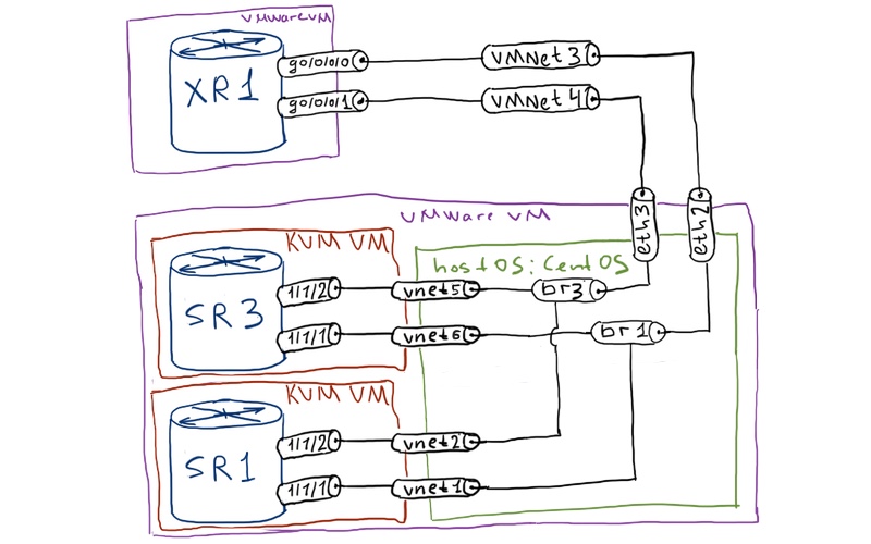
Physical topology for our lab doesn’t change:
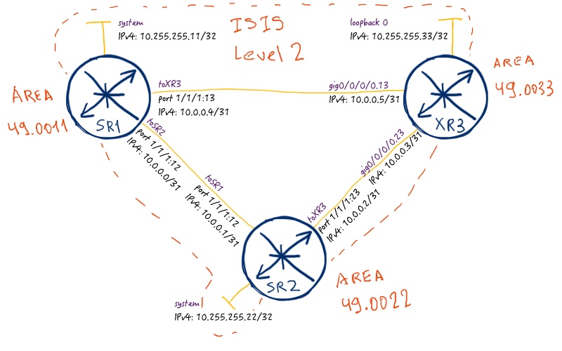
The logical topology for the current lab is just the same as it was in the previous one for VPWS:
In the current topology we are still using ISIS as our routing protocol (IGP). MPLS forwarding plane in this article is built using SPRING (Segment Routing), so we testing the most recent technology in real cases. As VPLS is multipoint topology, all our routers will be PE, so we’ll configure VPLS instances at each router.
Unfortunately Cisco IOS XRv doesn’t support data plane for L2 services, so we can test VPLS only between SR1 and SR2 (XR3 can be P router in this case).
Initial configuration for the lab is in the following files:
Refer to the article about VPWS to get understanding about MPLS service framework in Nokia (Alcatel-Lucent) SR OS and Cisco IOS XR.
LDP-based VPLS
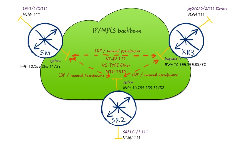
Let’s start with VPLS option, which uses LDP for signaling. It doesn’t support auto-discovery, like BGP-based VPLS does, so addition of each new site to VPLS requires reconfiguration of all sites. On the other hand, configuration itself is easier, as you strictly configures VC-IDs. Here is the topology of our service:
In order for VPLS to get into operation, VC-ID, VC-TYPE and MTU must match across all configured neighbors.
As we use all our routers as PE, so we configure all of them for new instance:
A:SR2>edit-cfg# candidate view
—————————
configure
router
ldp
no shutdown
exit
exit
service
customer 2 create
description “CUST_A”
exit
sdp 11 mpls create
far-end 10.255.255.11
sr-isis
path-mtu 1518
no shutdown
exit
sdp 33 mpls create
far-end 10.255.255.33
sr-isis
path-mtu 1518
no shutdown
exit
vpls “111” customer 2 create
sap “1/1/2:111” create
exit
mesh-sdp “11:111” create
control-word
no shutdown
exit
mesh-sdp “33:111” create
control-word
no shutdown
exit
no shutdown
exit
exit
exit
—————————
In Nokia (Alcatel-Lucent) SR OS we configure first of all SDPs and map them to SPRING (Segment Routing) MPLS LSPs. Point out that we have to increase path-mtu manually at SDP level, though in the production network you must avoid it. The reason for that is check performed by Nokia (Alcatel-Lucent) SR OS regarding different MTUs. See the in the detailed explanation in lessons learned. There are also two particular things regarding VPLS configuration itself. First, “vpls id” must match VC-ID for LDP session, it’s possible to change this behavior but it’s better to follow it as best practice. Second, you configure “mesh-sdp” (rather than “spoke-sdp” as we did in VPWS, because “mesh-sdp” implement split-horizon rule.
In Cisco IOS XR we configure customer interface as “l2transport” to put it into switching mode. The VPLS service is configured into “bridge-domain VPLS_LDP” context, where “VPLS_LDP’ is arbitrary name. Pay attention that you configure LDP neighbors with corresponding VC-ID (or PW-ID in Cisco terminology) under VFI (virtual forwarding instance) context.
In Cisco IOS XR you don’t need to map VPLS to any MPLS transport LSP, as done automatically via next hop lookup in FIB/LFIB
Actually VFI in Cisco IOS XR does just the same, what “mesh-sdp” does in Nokia (Alcatel-Lucent) SR OS; it implements split-horizon rule. You can configure “spoke-sdp” in VPLS in SR OS, when you build H-VPLS. Just in the same way you can configure LDP neighbor in bridge-domain (VPLS instance) without VFI for H-VPLS in IOS XR.
Well, let’s see what we have in outputs of show commands. Before we go into details of checking the configuration of any MPLS service, we should check if we have established MPLS LSP to corresponding PE:
For more information about SPING (Segment Routing) operation and configuration refer to this article.
Ok, we see that we have all LSPs configured and working. Pay attention that you have tunnels both from SPRING and from SDP configuration. Now it is turn to review all configured services to define interesting one:
A:SR1# show service service-using
============================================================================
Services
============================================================================
ServiceId Type Adm Opr CustomerId Service Name
—————————————————————————-
111 VPLS Up Up 2
2147483648 IES Up Down 1 _tmnx_InternalIesService
2147483649 intVpls Up Down 1 _tmnx_InternalVplsService
—————————————————————————-
Matching Services : 3
—————————————————————————-
============================================================================
Up to now only one VPLS is configured (besides two default services), so it’s easy to find it. Let’s review operational status of the VPLS components:
A:SR1# show service id 111 base
============================================================================
Service Basic Information
============================================================================ Service Id : 111 Vpn Id : 0 Service Type : VPLS
Name : (Not Specified)
Description : (Not Specified)
Customer Id : 2 Creation Origin : manual
Last Status Change: 10/25/2016 18:49:05
Last Mgmt Change : 10/25/2016 18:48:55
Etree Mode : Disabled Admin State : Up Oper State : Up MTU : 1514 Def. Mesh VC Id : 111
SAP Count : 1 SDP Bind Count : 2
Snd Flush on Fail : Disabled Host Conn Verify : Disabled
SHCV pol IPv4 : None
Propagate MacFlush: Disabled Per Svc Hashing : Disabled
Allow IP Intf Bind: Disabled
Fwd-IPv4-Mcast-To*: Disabled Fwd-IPv6-Mcast-To*: Disabled
Def. Gateway IP : None
Def. Gateway MAC : None
Temp Flood Time : Disabled Temp Flood : Inactive
Temp Flood Chg Cnt: 0
SPI load-balance : Disabled
TEID load-balance : Disabled
Src Tep IP : N/A
VSD Domain : <none>
—————————————————————————-
Service Access & Destination Points
—————————————————————————-
Identifier Type AdmMTU OprMTU Adm Opr
—————————————————————————-
sap:1/1/2:111 q-tag 1518 1518 Up Up
sdp:22:111 M(10.255.255.22) Mesh 1518 1518 Up Up
sdp:33:111 M(10.255.255.33) Mesh 1518 1518 Up Up
============================================================================
* indicates that the corresponding row element may have been truncated.
Here you see useful information like Service MTU, associated SAP/SDP and their operational status. To display the detailed parameters of SDP use the following command:
A:SR1# show service id 111 sdp 33:111 detail
============================================================================
Service Destination Point (Sdp Id : 33:111) Details
============================================================================
—————————————————————————-
Sdp Id 33:111 -(10.255.255.33)
—————————————————————————-
Description : (Not Specified) SDP Id : 33:111 Type : Mesh
Mesh Descr : (Not Specified)
Split Horiz Grp : (Not Specified)
Etree Root Leaf Tag: Disabled Etree Leaf AC : Disabled VC Type : Ether VC Tag : n/a Admin Path MTU : 1518 Oper Path MTU : 1518 Delivery : MPLS
Far End : 10.255.255.33
Tunnel Far End : n/a LSP Types : SR-ISIS
Hash Label : Disabled Hash Lbl Sig Cap : Disabled
Oper Hash Label : Disabled
Entropy Label : Disabled Admin State : Up Oper State : Up MinReqd SdpOperMTU : 1518
Acct. Pol : None Collect Stats : Disabled Ingress Label : 262139 Egress Label : 24008
Ingr Mac Fltr-Id : n/a Egr Mac Fltr-Id : n/a
Ingr IP Fltr-Id : n/a Egr IP Fltr-Id : n/a
Ingr IPv6 Fltr-Id : n/a Egr IPv6 Fltr-Id : n/a
Admin ControlWord : Preferred Oper ControlWord : True
BFD Template : None
BFD-Enabled : no BFD-Encap : ipv4
Last Status Change : 10/25/2016 18:51:45 Signaling : TLDP
Last Mgmt Change : 10/25/2016 18:48:55
============================================================================
FC Mapping Table
============================================================================
FC Name LSP Name
—————————————————————————-
No FC Mappings
—————————————————————————-
Segment Routing
—————————————————————————- ISIS : enabled LSP Id : 524292
Oper Instance Id : 0
OSPF : disabled
TE-LSP : disabled
—————————————————————————-
Number of SDPs : 1
—————————————————————————-
============================================================================
A lot of output is similar to the once, we saw in the VPWS. What is different is SDP type that is set to “Mesh”. Also you can see that LSP Id associated with this SDP is 524292, what corresponds to SR-ISIS LSP, which you have seen in the first show output in this article. As LDP is signaling protocol for this type of VPLS, information about peers VC-ID, VC-TYPE and MTU, as well as MPLS service label, you can found in LIB:
A:SR1# show router ldp binding service service-id 111 detail
============================================================================
LDP Bindings (IPv4 LSR ID 10.255.255.11)
(IPv6 LSR ID ::)
============================================================================
Legend: U – Label In Use, N – Label Not In Use, W – Label Withdrawn
S – Status Signaled Up, D – Status Signaled Down
E – Epipe Service, V – VPLS Service, M – Mirror Service
A – Apipe Service, F – Fpipe Service, I – IES Service, R – VPRN service
P – Ipipe Service, WP – Label Withdraw Pending, C – Cpipe Service
BU – Alternate For Fast Re-Route, TLV – (Type, Length: Value)
LF – Lower FEC, UF – Upper FEC, e – Label ELC
============================================================================
LDP Service FEC 128 Bindings
============================================================================ Type : V-Eth VcId : 111 SvcId : 111 SdpId : 33
Peer Address : 10.255.255.33:0
Vc-switching : No LMTU : 1500 RMTU : 1500 Egr. Lbl : 24008S Egr. Ctl Word : Yes
Egr. Flags : None Egr. Status Bits : Supported (0x0)
Egr. Flow Label Tx : No Egr. Flow Label Rx : No
Egr. PW Status Sig : Enabled
Egr. Vccv CV Bits : lsp-ping
Egr. Vccv CC Bits : pwe3-control-word router-alert-label mpls-demux-label-tl1 Ing. Lbl : 262139U Ing. Ctl Word : Yes
Ing. Flags : None Ing. Status Bits : N/A
Ing. Flow Label Tx : No Ing. Flow Label Rx : No
Ing. Wdraw Reason : N/A
Ing. PW Status Sig : Disabled
Ing. Vccv CV Bits : lsp-ping bfd-fault-detect
Ing. Vccv CC Bits : pwe3-control-word router-alert-label
—————————————————————————-
============================================================================
No. of VC Labels: 2
============================================================================
For VPLS we are able to configure Ethernet type of pseudowire, therefore we save 4 bytes on dot1q tag. In VPWS we haven’t achieved such option in interoperable scenario.
All of the most important parameters of VPLS we have reviewed from Nokia (Alcatel-Lucent) SR OS prospective. Let’s check Cisco IOS XR side.
We are starting with checking LFIB:
RP/0/0/CPU0:XR3#show mpls forwarding
Local Outgoing Prefix Outgoing Next Hop Bytes
Label Label or ID Interface Switched
—— ———– —————— ———— ————— ——— 16011 500011 No ID Gi0/0/0/0.13 10.0.0.4 594 16022 500022 No ID Gi0/0/0/0.23 10.0.0.2 594
24000 Pop SR Adj (idx 1) Gi0/0/0/0.13 10.0.0.4 0
24001 Pop SR Adj (idx 3) Gi0/0/0/0.13 10.0.0.4 0
24002 Pop SR Adj (idx 1) Gi0/0/0/0.23 10.0.0.2 0
24003 Pop SR Adj (idx 3) Gi0/0/0/0.23 10.0.0.2 0
24006 500011 10.255.255.11/32 Gi0/0/0/0.13 10.0.0.4 362
24007 500022 10.255.255.22/32 Gi0/0/0/0.23 10.0.0.2 362
24008 Pop PW(10.255.255.11:111) \
BD=1 point2point 0
24009 Pop PW(10.255.255.22:111) \
BD=1 point2point 0
The first two entries relate to SPRING (Segment Routing). As we see that there are some bytes switched, it means that SPRING MPLS LSPs are up and running. Let’s check or L2VPN services:
RP/0/0/CPU0:XR3#show l2vpn bridge-domain brief
Legend: pp = Partially Programmed.
Bridge Group:Bridge-Domain Name ID State Num ACs/up Num PWs/up
——————————– —– ————– ———— ———- CUST_A:VPLS_LDP 1 up 1/1 2/2
!
!
RP/0/0/CPU0:XR3#show l2vpn bridge-domain bd-name VPLS_LDP
Legend: pp = Partially Programmed. Bridge group: CUST_A, bridge-domain: VPLS_LDP, id: 1, state: up, ShgId: 0, MSTi: 0
Aging: 300 s, MAC limit: 4000, Action: none, Notification: syslog
Filter MAC addresses: 0
ACs: 1 (1 up), VFIs: 1, PWs: 2 (2 up), PBBs: 0 (0 up)
List of ACs:
Gi0/0/0/0.111, state: up, Static MAC addresses: 0
List of Access PWs:
List of VFIs: VFI VPLS_111 (up) Neighbor 10.255.255.11 pw-id 111, state: up, Static MAC addresses: 0 Neighbor 10.255.255.22 pw-id 111, state: up, Static MAC addresses: 0
We see that service seems to work correctly (at least signaling). It doesn’t only seem, it’s really so, but due to absence of data plane for L2 switching in Cisco IOS XR we can’t check it. Detail evaluation of the VPLS parameters is long and boring, so I’m providing only the most interesting part:
RP/0/0/CPU0:XR3#show l2vpn bridge-domain bd-name VPLS_LDP detail
Bridge group: CUST_A, bridge-domain: VPLS_LDP, id: 1, state: up, ShgId: 0, MSTi: 0
Coupled state: disabled MAC learning: enabled MAC withdraw: enabled
MAC withdraw for Access PW: enabled
MAC withdraw sent on: bridge port up
MAC withdraw relaying (access to access): disabled Flooding: Broadcast & Multicast: enabled Unknown unicast: enabled MAC aging time: 300 s, Type: inactivity MAC limit: 4000, Action: none, Notification: syslog
ACs: 1 (1 up), VFIs: 1, PWs: 2 (2 up), PBBs: 0 (0 up)
List of ACs: AC: GigabitEthernet0/0/0/0.111, state is up
List of VFIs:
VFI VPLS_111 (up)
PW: neighbor 10.255.255.11, PW ID 111, state is up ( established ) PW class VPLS_CW, XC ID 0xff000001 Encapsulation MPLS, protocol LDP
Source address 10.255.255.33 PW type Ethernet, control word enabled, interworking none
Sequencing not set
MPLS Local Remote
———— —————————— ———————- Label 24008 262139
Group ID 0x1 0x0
Interface VPLS_111 unknown MTU 1500 1500 Control word enabled enabled PW type Ethernet Ethernet
VCCV CV type 0x2 0x6
(LSP ping verification) (LSP ping verification)
(BFD PW FD only)
VCCV CC type 0x7 0x3
(control word) (control word)
(router alert label) (router alert label)
(TTL expiry)
———— —————————— ———————-
In Nokia (Alcatel-Lucent) SR OS we can see the parameters of MAC learning in FDB (forwarding data base) that is associated with VPLS:
A:SR1# show service id 111 fdb
============================================================================
Forwarding Database, Service 111
============================================================================
Service Id : 111 Mac Move : Disabled
Primary Factor : 3 Secondary Factor : 2
Mac Move Rate : 2 Mac Move Timeout : 10
Mac Move Retries : 3 Table Size : 250 Total Count : 0
Learned Count : 0 Static Count : 0
OAM MAC Count : 0 DHCP MAC Count : 0
Host MAC Count : 0 Intf MAC Count : 0
Spb Count : 0 Cond MAC Count : 0
BGP EVPN Count : 0 EVPN Static Cnt : 0 Remote Age : 900 Local Age : 300
High Watermark : 95% Low Watermark : 90% Mac Learning : Enabled Discard Unknown : Disabled Mac Aging : Enabled Relearn Only : False
Mac Subnet Len : 48
============================================================================
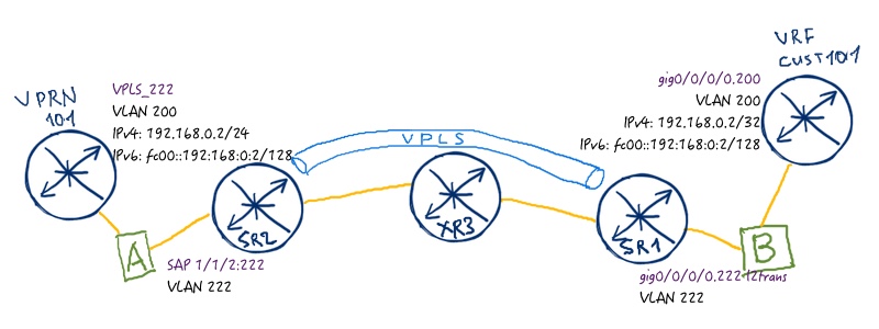
We can test VPLS between SR1 and SR2, as Nokia (Alcatel-Lucent) VSR supports all features that real SR 7750 devices including MPLS L2 services. We’ll temporary disable direct connection between SR1 and SR2 in order to make traffic pass XR3 as a transit node. As emulation of customer devices, I’ll create VPRN 100 at SR1 and VRF CUST100 at XR3. Linux bridge performs function of dot1q tag rewrite in order traffic with appropriate tag comes to VPLS. So our test topology looks like as follows:
The configuration for our devices looks as follows:
Nokia (Alcatel-Lucent) VSR (SR 7750)
Cisco IOS XR (ASR 9000)
SR1
XR1
A:SR1>edit-cfg# candidate view
—————————
configure
service
vprn 100 customer 2 create
route-distinguisher 10.255.255.11:100
interface VPLS111_CUST create
address 192.168.0.1/24
ipv6
address fc00::192:168:0:1/120
link-local-address fe80::51:111:1
exit
sap 1/1/2:100 create
exit
no shutdown
exit
no shutdown
exit
exit
exit
—————————
[root@localhost ~]#
/sbin/vconfig add eth2 100
/sbin/vconfig add vnet2 111
ifconfig eth2.100 up
ifconfig vnet2.111 up
brctl addbr br101
brctl addif br101 eth2.100
brctl addif br101 vnet2.111
ifconfig br101 up
[root@localhost ~]#
/sbin/vconfig add vnet6 111
/sbin/vconfig add vnet2 100
ifconfig vnet6.111 up
ifconfig vnet2.100 up
brctl addbr br102
brctl addif br102 vnet6.111
brctl addif br102 vnet2.100
ifconfig br102 up
Let’s ping Site B of the Customer A (VRF CUST100 at XR3) from Site A (VPRN 100 at SR1) and make a dump in Wireshark:
A:SR1# ping router 100 192.168.0.2 count 1
PING 192.168.0.2 56 data bytes
64 bytes from 192.168.0.2: icmp_seq=1 ttl=255 time=10.8ms.
—- 192.168.0.2 PING Statistics —-
1 packet transmitted, 1 packet received, 0.00% packet loss
round-trip min = 10.8ms, avg = 10.8ms, max = 10.8ms, stddev = 0.000ms
MAC learning phase is omitted in order to save the space. Refer to sources mentioned in the beginning.
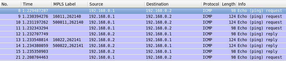
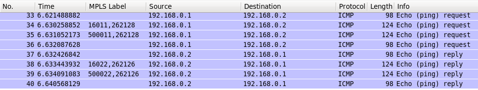
Traffic dump from Wireshark show the journey of our packet across MPLS network:
The first four steps form forward path (VPRN_100) à (SR2) à (XR3) à (SR1) à (VRF_CUST100):
Unlabeled packet comes from VPRN_100 at SR2.
SR2 pushes MPLS service label associated egress PE for this service (262140), then it pushes MPLS transport label from SPRING (16011).
A:SR2# show router ldp bindings services service-id 111 detail | match expression “Lbl|Peer”
Peer Address : 10.255.255.11:0
Egr. Lbl : 262141 Egr. Ctl Word : Yes
Ing. Lbl : 262140U Ing. Ctl Word : Yes
!
!
A:SR2# show router tunnel-table protocol isis 10.255.255.11/32 detail | match Label
Tunnel Label : 16011 Tunnel Metric : 20
Tunnel MTU : 1496 Max Label Stack : 1
XR3 swaps MPLS transport label (16011 à 500011) without touching service label that remains the same (262140).
RP/0/0/CPU0:XR3#show mpls forwarding | include “16011|Label”
Label Label or ID Interface Switched
16011 500011 No ID Gi0/0/0/0.13 10.0.0.4 138294
SR1 pops MPLS transport label (500011) as it is tail-end for this MPLS LSP, then it pops service label (262140) and sends packet from the appropriate interface to VRF_CUST100.
The backward path follows the very same logic.
For VPLS operation the FDB, how is it called in Nokia (Alcatel-Lucent) SR OS, is one of the most important database, because there is located mapping of all MAC address to interfaces or pseudowires:
A:SR2# show service id 111 fdb detail
============================================================================
Forwarding Database, Service 111
============================================================================
ServId MAC Source-Identifier Type Last Change
Age
=—————————————————————————
111 00:50:56:3a:83:ff sdp:11:111 L/800 10/25/16 20:01:33
111 fa:ac:a6:14:01:03 sap:1/1/2:111 L/0 10/25/16 20:32:28
—————————————————————————-
No. of MAC Entries: 2
—————————————————————————-
Legend: L=Learned O=Oam P=Protected-MAC C=Conditional S=Static
============================================================================
In Cisco IOS XR we can’t show the same table because there is no L2 data plane in Cisco IOS XR. What about IPv6? Let’s test how this traffic is transported over VPLS:
A PING fc00::192:168:0:2 56 data bytes
64 bytes from fc00::192:168:0:2 icmp_seq=1 hlim=64 time=20.6ms.
—- fc00::192:168:0:2 PING Statistics —-
1 packet transmitted, 1 packet received, 0.00% packet loss
round-trip min = 20.6ms, avg = 20.6ms, max = 20.6ms, stddev = 0.000ms
And here is the actual packet flow:
As you can imaging, there is no difference for VPLS between IPv4 and IPv6 traffic, as we transit layer 2 frames including Ethernet header, where Ethertype for IPv4/IPv6 is encoded.
Before we go to the next VPLS option, we bring back link between SR1 and SR2.
BGP-based VPLS
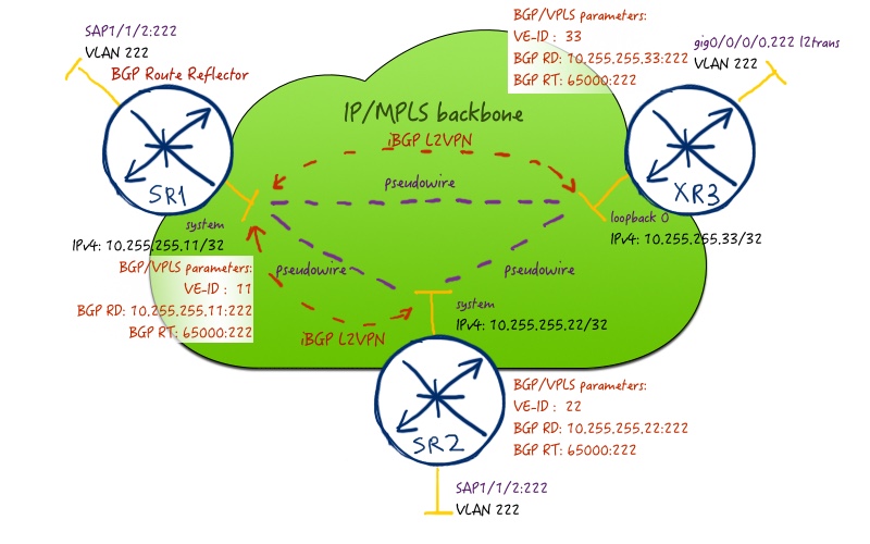
This type of VPLS provides you ease of scale and signaling in your network, because you don’t need to change configuration of existing VPLS peers when adding new PE. On the other hand you have to tune BGP in order to get satisfactory speed of convergence. Here is the service topology that we are going to configure:
In order to remove full-mesh of iBGP sessions, we configure SR1 as BGP route reflector. The address family is the same, as it was in BGP-based VPWS – L2VPN (AFI/SAFI 25/65). We use 65000:222 as route-target for this VPN in order to distribute the VPLS information. So, let’s perform the necessary configuration:
In Nokia (Alcatel-Lucent) SR OS first of all we establish BGP neighbors with other PEs in corresponding address-family (remember that SR1 is BGP route reflector). Then we have to create new set of SDPs, which are mapped to newly created SDP-group “SDP_BGP_AUTO”. We need new SDPs, because new type of signaling (BGP instead of LDP) is used. SDP-group is used in order to map SDPs to BGP discovered next-hops via PW-template. PW-template is also used for enabling control-word. The VPLS service itself has a number of important component that is BGP specific, but the first one VPN-ID must be configured at the time of VPLS-service creation. It must be the same across all PE involved in this VPLS (the same is true for BGP route-targets). The last important element for BGP signaling is VE-ID. It works in the same way as in VPWS and must be unique inside VPLS cloud.
In Cisco IOS XR you do approximately the same configuration with the exception of new SDP, as there is no SDPs in Cisco. MPLS LSPs are completely separated from services, that’s why mapping service to MPLS LSP is done solely by next-hop lookup in routing table.
Also pay attention that we have changed service MTU in Nokia (Alcatel-Lucent) SR OS. Service MTU handling is different for BGP and for LDP at Cisco IOS XR
We see that peering is established in the proper address family. Let’s check the summary parameters of this BGP-based VPLS:
A:SR2# show service id 222 base
============================================================================
Service Basic Information
============================================================================ Service Id : 222 Vpn Id : 222 Service Type : VPLS
Name : (Not Specified)
Description : (Not Specified)
Customer Id : 2 Creation Origin : manual
Last Status Change: 10/26/2016 12:33:11
Last Mgmt Change : 10/26/2016 14:04:18
Etree Mode : Disabled
Admin State : Up Oper State : Up MTU : 1500 Def. Mesh VC Id : 222
SAP Count : 1 SDP Bind Count : 2
Snd Flush on Fail : Disabled Host Conn Verify : Disabled
SHCV pol IPv4 : None
Propagate MacFlush: Disabled Per Svc Hashing : Disabled
Allow IP Intf Bind: Disabled
Fwd-IPv4-Mcast-To*: Disabled Fwd-IPv6-Mcast-To*: Disabled
Def. Gateway IP : None
Def. Gateway MAC : None
Temp Flood Time : Disabled Temp Flood : Inactive
Temp Flood Chg Cnt: 0
SPI load-balance : Disabled
TEID load-balance : Disabled
Src Tep IP : N/A
VSD Domain : <none>
—————————————————————————-
Service Access & Destination Points
—————————————————————————-
Identifier Type AdmMTU OprMTU Adm Opr
—————————————————————————-
sap:1/1/2:222 q-tag 1518 1518 Up Up sdp:1:4294967293 S(10.255.255.11) BgpVpls 1518 1518 Up Up sdp:3:4294967294 S(10.255.255.33) BgpVpls 1518 1518 Up Up
============================================================================
* indicates that the corresponding row element may have been truncated.
You see that SDP VC-IDs are automatically configured for BGP-derived pseudowires. Nevertheless we see that all of them are up and running. Let’s check the details for SDP that leads to XR3:
A:SR2# show service id 222 sdp 3 detail
============================================================================
Service Destination Point (Sdp Id : 3) Details
============================================================================
—————————————————————————-
Sdp Id 3:4294967294 -(10.255.255.33)
—————————————————————————-
Description : (Not Specified) SDP Id : 3:4294967294 Type : BgpVpls PW-Template Id : 222
Split Horiz Grp : (Not Specified)
Etree Root Leaf Tag: Disabled Etree Leaf AC : Disabled VC Type : Ether VC Tag : n/a Admin Path MTU : 1518Oper Path MTU : 1518
Delivery : MPLS
Far End : 10.255.255.33
Tunnel Far End : n/a LSP Types : SR-ISIS
Hash Label : Disabled Hash Lbl Sig Cap : Disabled
Oper Hash Label : Disabled
Entropy Label : Disabled
Admin State : Up Oper State : Up MinReqd SdpOperMTU : 1504
Acct. Pol : None Collect Stats : Disabled Ingress Label : 262119 Egress Label : 24047
Ingr Mac Fltr-Id : n/a Egr Mac Fltr-Id : n/a
Ingr IP Fltr-Id : n/a Egr IP Fltr-Id : n/a
Ingr IPv6 Fltr-Id : n/a Egr IPv6 Fltr-Id : n/a Admin ControlWord : Preferred Oper ControlWord : True
BFD Template : None
BFD-Enabled : no BFD-Encap : ipv4
Last Status Change : 10/26/2016 12:34:12 Signaling : BGP
Last Mgmt Change : 10/26/2016 12:34:12
Endpoint : N/A Precedence : 4
PW Status Sig : Enabled MAC Learning : Enabled Discard Unkwn Srce: Disabled MAC Aging : Enabled
=============================================================================
—————————————————————————-
Segment Routing
—————————————————————————- ISIS : enabled LSP Id : 524292
Oper Instance Id : 0
OSPF : disabled
TE-LSP : disabled
—————————————————————————–
=============================================================================
We see service labels that are used for this pseudowire and mapping of the VPLS to actual MPLS LSP. Again we have VC-TYPE “Ether” that means that we transport Ethernet frame without tag over MPLS. You see that signaling type is BGP. If you forgot (or don’t know) which type of signaling and/or MPLS LSP is used for SDP, you can check by the following command:
A:SR2# show service sdp
============================================================================
Services: Service Destination Points
============================================================================
SdpId AdmMTU OprMTU Far End Adm Opr Del LSP Sig
—————————————————————————-
1 1518 1518 10.255.255.11 Up Up MPLS I BGP
3 1518 1518 10.255.255.33 Up Up MPLS I BGP
11 1518 1518 10.255.255.11 Up Up MPLS I TLDP
33 1518 1518 10.255.255.33 Up Up MPLS I TLDP
—————————————————————————-
Number of SDPs : 4
—————————————————————————-
Legend: R = RSVP, L = LDP, B = BGP, M = MPLS-TP, n/a = Not Applicable
I = SR-ISIS, O = SR-OSPF, T = SR-TE, F = FPE
============================================================================
BGP parameters of our local VPLS entity helps you by troubleshooting to understand what route-targets are send/received and what is our VE-ID:
A:SR2# show service id 222 bgp
============================================================================
BGP Information
============================================================================
Vsi-Import : None
Vsi-Export : None Route Dist : 10.255.255.22:222 Oper Route Dist : 10.255.255.22:222
Oper RD Type : configured Rte-Target Import : 65000:222Rte-Target Export: 65000:222
Oper RT Imp Origin : configured Oper RT Import : 65000:222
Oper RT Exp Origin : configured Oper RT Export : 65000:222
PW-Template Id : 222 PW-Template SHG : None
Oper Group : None
Mon Oper Group : None
BFD Template : None
BFD-Enabled : no BFD-Encap : ipv4
Import Rte-Tgt : None
—————————————————————————-
============================================================================
!
!
A:SR2# show service id 222 bgp-vpls
============================================================================
BGP VPLS Information
============================================================================
Max Ve Id : 1000 Admin State : Enabled VE Name : SR2 VE Id : 22
PW Tmpl used : 222
============================================================================
Signaling information from other PEs is available in BGP RIB. Here is the example of one route:
A:SR2# show router bgp routes l2-vpn rd 10.255.255.11:222 detail
===============================================================================
BGP Router ID:10.255.255.22 AS:65000 Local AS:65000
===============================================================================
Legend –
Status codes : u – used, s – suppressed, h – history, d – decayed, * – valid
l – leaked, x – stale, > – best, b – backup, p – purge
Origin codes : i – IGP, e – EGP, ? – incomplete
===============================================================================
BGP L2VPN Routes
===============================================================================
Original Attributes
Route Type : VPLS Route Dist. : 10.255.255.11:222 VeId : 11 Block Size : 8 Base Offset : 9 Label Base : 262132 Nexthop : 10.255.255.11 From : 10.255.255.11
Res. Nexthop : n/a
Local Pref. : 100 Interface Name : NotAvailable
Aggregator AS : None Aggregator : None
Atomic Aggr. : Not Atomic MED : 0
AIGP Metric : None
Connector : None
Community : target:65000:222
l2-vpn/vrf-imp:Encap=19: Flags=-C: MTU=1500: PREF=0
Cluster : No Cluster Members
Originator Id : None Peer Router Id : 10.255.255.11
Flags : Used Valid Best IGP
Route Source : Internal
AS-Path : No As-Path
Route Tag : 0
Neighbor-AS : N/A
Orig Validation: N/A
Source Class : 0 Dest Class : 0
Add Paths Send : Default
Last Modified : 02h01m37s
Let’s check Cisco IOS XR side. The first step is to check BGP peering for L2VPN:
RP/0/0/CPU0:XR3#show bgp l2vpn vpls summary
BGP router identifier 10.255.255.33, local AS number 65000
BGP generic scan interval 60 secs
Non-stop routing is enabled
BGP table state: Active
Table ID: 0x0 RD version: 0
BGP main routing table version 24
BGP NSR Initial initsync version 2 (Reached)
BGP NSR/ISSU Sync-Group versions 0/0
BGP scan interval 60 secs
BGP is operating in STANDALONE mode.
Process RcvTblVer bRIB/RIB LabelVer ImportVer SendTblVer StandbyVer
Speaker 24 24 24 24 24 0
Neighbor Spk AS MsgRcvd MsgSent TblVer InQ OutQ Up/Down St/PfxRcd
10.255.255.11 0 65000 292 282 24 0 0 02:18:50 6
As peering is established and works well, we can go the next step in reviewing the operation of BGP-based VPLS. What about label blocks, which are used for service labels?
RP/0/0/CPU0:XR3#show l2vpn discovery
Service Type: VPLS, Connected
List of VPNs (1 VPNs):
Bridge group: CUST_A, bridge-domain: VPLS_BGP, id: 0, signaling protocol: BGP
List of Local Edges (1 Edges):
Local Edge ID: 33, Label Blocks (3 Blocks)
Label base Offset Size Time Created
———- —— —- ——————-
24030 10 10 10/18/2016 20:33:46
24045 20 10 10/18/2016 20:44:08
24015 30 10 10/18/2016 20:14:52
List of Remote Edges (2 Edges):
Remote Edge ID: 11, NLRIs (3 NLRIs)
Label base Offset Size Peer ID Time Created
———- —— —- ————— ——————-
262132 9 8 10.255.255.11 10/18/2016 20:33:46
262110 17 8 10.255.255.11 10/18/2016 20:44:08
262118 33 8 10.255.255.11 10/18/2016 20:33:46
Remote Edge ID: 22, NLRIs (3 NLRIs)
Label base Offset Size Peer ID Time Created
———- —— —- ————— ——————-
262111 9 8 10.255.255.22 10/18/2016 20:44:08
262127 17 8 10.255.255.22 10/18/2016 20:44:08
262119 33 8 10.255.255.22 10/18/2016 20:44:08
As you can, here we have three main parameters for each session: label base, VE-ID (Edge ID) and offset. When we use BGP-based VPLS, BGP doesn’t signal each particular label. It signals mentioned parameters, so that each router calculates label itself. As all routers use the same algorithm, calculated labels match across all routers. At the following output you see summary parameters of configured VPLS:
RP/0/0/CPU0:XR3#show l2vpn bridge-domain brief
Legend: pp = Partially Programmed.
Bridge Group:Bridge-Domain Name ID State Num ACs/up Num PWs/up
——————————– —– ————– ———— ————-
CUST_A:VPLS_BGP 0 up 1/1 2/2
CUST_A:VPLS_LDP 1 up 1/1 2/2
!
!
RP/0/0/CPU0:XR3#show l2vpn bridge-domain bd-name VPLS_BGP
Legend: pp = Partially Programmed.
Bridge group: CUST_A, bridge-domain: VPLS_BGP, id: 0, state: up, ShgId: 0, MSTi: 0
Aging: 300 s, MAC limit: 4000, Action: none, Notification: syslog
Filter MAC addresses: 0
ACs: 1 (1 up), VFIs: 1, PWs: 2 (2 up), PBBs: 0 (0 up)
List of ACs:
Gi0/0/0/0.222, state: up, Static MAC addresses: 0
List of Access PWs:
List of VFIs:
VFI VPLS_222 (up)
Neighbor 10.255.255.11 pw-id 222, state: up, Static MAC addresses: 0
Neighbor 10.255.255.22 pw-id 222, state: up, Static MAC addresses: 0
The most interesting part for us here is BGP-signaled pseudowired, so I provide only configuration of one of the. For more information about attached circuit (local interface) and other parameters refer to the LDP part:
RP/0/0/CPU0:XR3#show l2vpn bridge-domain bd-name VPLS_BGP detail
Legend: pp = Partially Programmed.
Bridge group: CUST_A, bridge-domain: VPLS_BGP, id: 0, state: up, ShgId: 0, MSTi: 0
List of VFIs:
VFI VPLS_222 (up) VPN-ID: 222, Auto Discovery: BGP, state is Provisioned (Service Connected) Route Distinguisher: 10.255.255.33:222 Import Route Targets: 65000:222 Export Route Targets: 65000:222 Signaling protocol: BGP Local VE-ID: 33 , Advertised Local VE-ID : 33
VE-Range: 10 PW: neighbor 10.255.255.11, PW ID 222, state is up ( established )
PW class not set, XC ID 0xff000003 Encapsulation MPLS, Auto-discovered (BGP), protocol BGP Source address 10.255.255.33
PW type VPLS, control word enabled, interworking none
Sequencing not set
MPLS Local Remote
———— —————————— ———————- Label 24031 262118 MTU 1500 1500 Control word enabled enabled PW type VPLS VPLS VE-ID 33 11
———— —————————— ———————-
Information about other PEs you can find in BGP RIB. You can spot that route is encoded as “VE-ID:Offset”:
RP/0/0/CPU0:XR3#show bgp l2vpn vpls rd 10.255.255.33:222
BGP router identifier 10.255.255.33, local AS number 65000
BGP generic scan interval 60 secs
Non-stop routing is enabled
BGP table state: Active
Table ID: 0x0 RD version: 0
BGP main routing table version 24
BGP NSR Initial initsync version 2 (Reached)
BGP NSR/ISSU Sync-Group versions 0/0
BGP scan interval 60 secs
Status codes: s suppressed, d damped, h history, * valid, > best
i – internal, r RIB-failure, S stale, N Nexthop-discard
Origin codes: i – IGP, e – EGP, ? – incomplete
Network Next Hop Rcvd Label Local Label
Route Distinguisher: 10.255.255.33:222 (default for vrf CUST_A:VPLS_BGP)
*>i11:9/32 10.255.255.11 262132 nolabel
*>i11:17/32 10.255.255.11 262110 nolabel
*>i11:33/32 10.255.255.11 262118 nolabel
*>i22:9/32 10.255.255.22 262111 nolabel
*>i22:17/32 10.255.255.22 262127 nolabel
*>i22:33/32 10.255.255.22 262119 nolabel
*> 33:10/32 0.0.0.0 nolabel 24030
*> 33:20/32 0.0.0.0 nolabel 24045
*> 33:30/32 0.0.0.0 nolabel 24015
Processed 9 prefixes, 9 paths
Pay attention that here you see not the actual label but rather the label base. In the previous output there was actual label. The detailed information is transferred in community (actually, extended community) field:
Everybody likes lab testing and verification, whereas the best type of verification is to ping or traceroute something. I like it as well, so let’s make small test that is similar to one we’ve done in the end of LDP part. Let’s create new VPRN 101 at SR1 and attach it to SR2 VPLS instance, whereas new VRF CUST101 at XR3 will be attached to SR1 VPLS instance. The direct link between SR1 and SR2 is temporary disabled in order to make traffic pass XR3. The topology for the simulation is the following:
The configuration is very simple and repeats what we have done in LDP part (besides VLAN numbers). Pay attention that IPv4 and IPv6 addresses are the same:
Nokia (Alcatel-Lucent) VSR (SR 7750)
Cisco IOS XR (ASR 9000)
SR1
XR1
A:SR1>edit-cfg# candidate view
—————————
configure
service
vprn 101 customer 2 create
route-distinguisher 10.255.255.11:101
interface VPLS222_CUST create
address 192.168.0.1/24
ipv6
address fc00::192:168:0:1/120
link-local-address fe80::51:222:1
exit
sap 1/1/2:200 create
exit
no shutdown
exit
no shutdown
exit
exit
exit
—————————
[root@localhost ~]#
/sbin/vconfig add eth2 200
/sbin/vconfig add vnet2 222
ifconfig eth2.200 up
ifconfig vnet2.222 up
brctl addbr br201
brctl addif br201 eth2.200
brctl addif br201 vnet2.222
ifconfig br201 up
[root@localhost ~]#
/sbin/vconfig add vnet6 222
/sbin/vconfig add vnet2 200
ifconfig vnet6.222 up
ifconfig vnet2.200 up
brctl addbr br202
brctl addif br202 vnet6.222
brctl addif br202 vnet2.200
ifconfig br202 up
Now it’s ping time:
*A:SR1# ping router 101 192.168.0.2 count 1
PING 192.168.0.2 56 data bytes
64 bytes from 192.168.0.2: icmp_seq=1 ttl=255 time=17.0ms.
—- 192.168.0.2 PING Statistics —-
1 packet transmitted, 1 packet received, 0.00% packet loss
round-trip min = 17.0ms, avg = 17.0ms, max = 17.0ms, stddev = 0.000ms
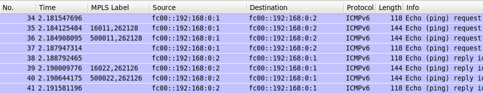
Wireshark shows how our brave ICMP packet travels from VPRN 101 to VRF CUST101 and back:
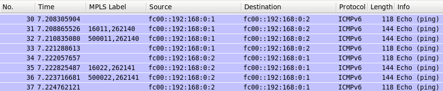
For the sake of consistency, let’s test IPv6 transmission as well:
*A:SR1# ping router 101 fc00::192:168:0:2 count 1
PING fc00::192:168:0:2 56 data bytes
64 bytes from fc00::192:168:0:2 icmp_seq=1 hlim=64 time=28.1ms.
—- fc00::192:168:0:2 PING Statistics —-
1 packet transmitted, 1 packet received, 0.00% packet loss
round-trip min = 28.1ms, avg = 28.1ms, max = 28.1ms, stddev = 0.000ms
Wireshark shows the same picture, as expected:
The final configs are here:
Lessons learned
Service MTU limits the frame size that is encapsulated in MPLS. Its value is is 1514 bytes by default in Nokia (Alcatel-Lucent) SR OS. Adding 4 bytes for control word we get 1518 bytes MTU, and this value must be lower or equal than SDP path-MTU. SDP path-MTU is calculated automatically from network-port MTU including all possible encapsulation. As we have 1518 bytes MTU at network port, the effective SDP path-MTU is 1492 bytes (1518 – 14 Eth header – 4 dot1Q header – 4 MPLS transport label – 4 bytes MPLS service label). There are two options what we can do (excluding change of network-port MTU):
Change SDP path-MTU to be equal or higher than service MTU.
Change service MTU to be equal or lower than SDP path-MTU.
The second option leads to necessity of MTU change at Cisco IOS XR side as well. So the service MTU at Nokia (Alcatel-Lucent) SR OS side will be 1488 and at Cisco IOS XT side will be 1474.
Then Cisco IOS XR performs automatic check if service MTU equals customer port MTU that is 1500 by default (and we haven’t changed it). If it isn’t equal, then VPLS is down. In our case we can’t change port MTU, as core-facing and customer-facing sub interfaces are configured on the same physical port, so we are getting into recursive loop.
If we change SDP path-MTU, we adjust it to service MTU without impacting anything else. But all the frames bigger than 1488 bytes (including Ethernet header) will be silently dropped.
MTU is one of the trickiest thing, when we are speaking about network communication in general and VPN services in particular.
Conclusion
VPLS is one of the most widely deployed technology for tunneling Ethernet packets across MPLS network. It’s often used not only in Service Provider networks for backhauling of different services in RAN (Radio Access Network) or connecting customers in Metro Access, but also in big data center networks or for data center interconnects (DCI). Building VPLS in multi-vendor network with Nokia (Alcatel-Lucent) SR OS and Cisco IOS XR is possible due to RFC nature of this technology. So far we have reviewed two the most widely used L2VPN services in MPLS network: VPWS and VPLS. In the next article we’ll speak about the newest one that is called EVPN (Ethernet VPN). Take care and good bye!