IP/LDP FRR/LFA and Remote LFA at Nokia (Alcatel-Lucent) SR OS and Cisco IOS XR
Anton Karneliuk
Hello my friend,
We have talked a lot about services that run on IP/MPLS network, but we have only once talked (link) about how to assure the service level. There are really lots of thinks we can do in this field, but one of the first and most important is the speed of restoration. That’s what I want to cover in current article.
1 2 3 4 5
No part of this blogpost could be reproduced, stored in a
retrieval system, or transmitted in any form or by any
means, electronic, mechanical or photocopying, recording,
or otherwise, for commercial purposes without the
prior permission of the author.
Brief overview
During discussing MPLS forwarding plane built with RSVP-TE we have reviewed the configuration and operation of fast reroute. It’s one of the most robust (probably the most robust) mechanism that can be implemented in the network. But what if you don’t have RSVP-TE? Does it mean that you can’t achieve fast convergence and service restoration in case of failure? The answer will be “it depends”. But generally we have a plenty of possibilities, what we can do to achieve fast convergence without RSVP-TE.
The first option is IP FRR (IP fast reroute) that can be implemented even without MPLS. The main idea is that router that makes protection performs SPF calculation also from the point of view of its adjacent routers (valid both for OSPF and ISIS) and if it can find alternative route (to the best one) to destination, and this route doesn’t pass our router, then we have backup route that is precalculated and installed in FIB. In case of failure, our router will immediately use the backup route without performing additional SPF. This feature is also called LFA (loop free alternative).
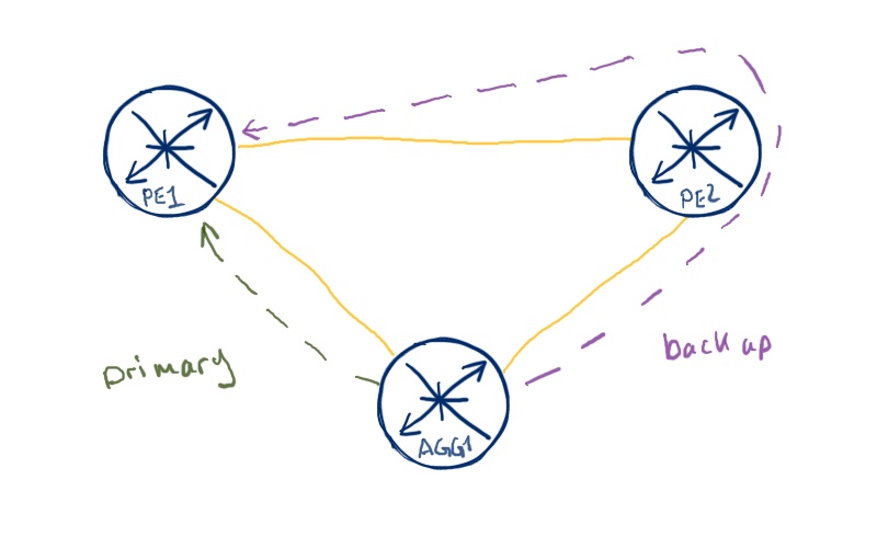
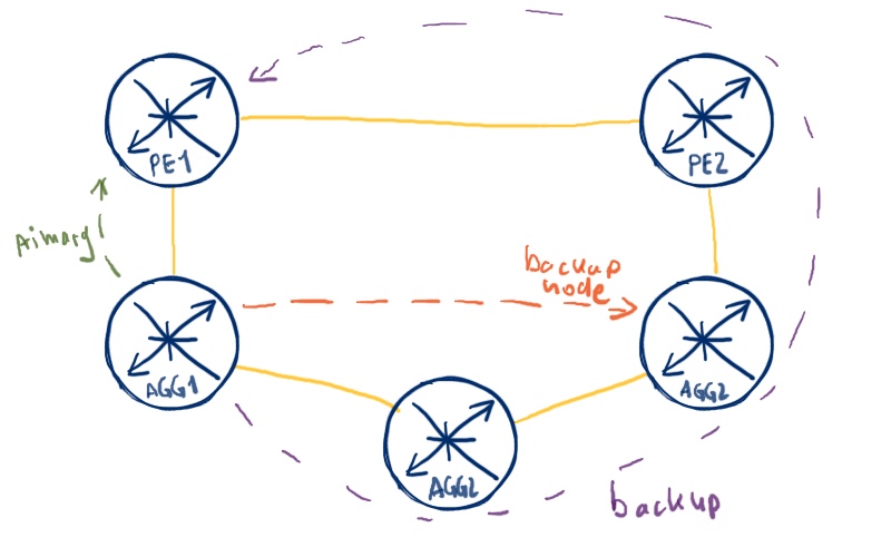
But what if our adjacent router doesn’t satisfy the criteria above? This case is valid especially for ring topologies, where we have numerous devices in the chain on the one hand and therefore limited option for backup route calculation. In RSVP-TE based MPLS we could build FRR tunnel and that’s it. Well, in the pure IP world there is no such solution, but LDP has such solution, which is called RLFA (Remote LFA). Unfortunately, this feature isn’t standardized, so each vendor has its own implementation. We’ll see further how to deal with it.
What are we going to test?
We’ll deploy and test configuration of IP FRR/LFA for IPv4/IPv6 prefixes in the mixed Nokia (Alcatel-Lucent) SR OS and Cisco IOS XR scenario. Then we’ll move to the IPv4/MPLS network and will test remote LFA (RLFA) in the same environment, but with a bit different topology to outline the use case for it.
Topology
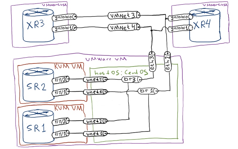
Thanks to the enhancement to my test lab mentioned in the previous article (link) I will use 4 virtual routers (2 Nokia (Alcatel-Lucent) VSRs and 2 Cisco IOS XRv:
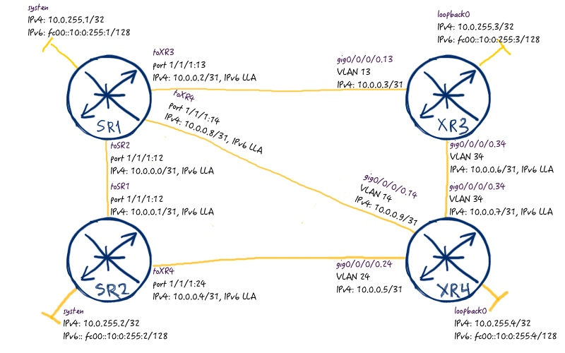
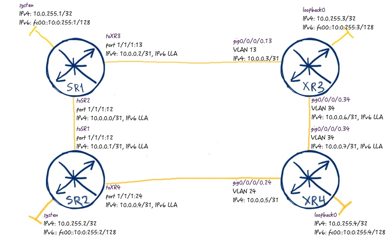
The following logical topology I’m gonna to configure for this FRR/LFA/RLFA lab:
As the routing protocol (IGP) IS-IS is used, though you can use OSPF, if you want. All the links have equal cost with the value of 10. For the first scenario, where we test fast reroute (FRR) / loopfree alternative (LFA) for IPv4 and IPv6, the provided topology is enough.
The main prerequisite for building any advanced mechanism of resiliency, regardless of dealing with Nokia (Alcatel-Lucent) SR OS or Cisco IOS XR, is up and running IGP. As it’s already done, all we need is just to activate FRR with a couple of commands.
For any Cisco platform (IOS, IOS XE, IOS XR, NX-OS) the recommended mode is “per-prefix”, because it provides much more flexibility than “per-link”. In today’s reality the CPU and memory capacity isn’t usually the case so I don’t want to go in that discussion. For Nokia (Alcatel-Lucent) SR OS you don’t have possibility to choose the type for FRR calculation, so it isn’t applicable. By the way Nokia (Alcatel-Lucent) SR OS implements by default per-link calculation.
Let’s start our check with Nokia (Alcatel-Lucent) SR OS router. There is one nice command that shows you in percentage, how good you are protected. Certainly our goal is to see 100% here:
The routes themselves you can see with the following command.
A:SR1# show router route-table ipv4 alternative
===============================================================================
Route Table (Router: Base)
===============================================================================
Dest Prefix[Flags] Type Proto Age Pref
Next Hop[Interface Name] Metric
Alt-NextHop Alt-
Metric
——————————————————————————-
10.0.0.0/31 Local Local 00h22m27s 0
toSR2 0
10.0.0.2/31 Local Local 00h22m27s 0
toXR3 0
10.0.0.8/31 Local Local 00h22m06s 0
toXR4 0
10.0.255.1/32 Local Local 00h22m39s 0
system 0
10.0.255.2/32 Remote ISIS 00h17m22s 18
10.0.0.1 10
10.0.0.9 (LFA) 20
10.0.255.3/32 Remote ISIS 00h13m24s 18
10.0.0.3 10
10.0.0.9 (LFA) 20
10.0.255.4/32 Remote ISIS 00h07m50s 18
10.0.0.9 10
10.0.0.1 (LFA) 20
——————————————————————————-
No. of Routes: 7
===============================================================================
At Cisco IOS XR you can see all the backup routes either in route table:
RP/0/0/CPU0:XR3#show route ipv4
C 10.0.0.2/31 is directly connected, 01:34:09, GigabitEthernet0/0/0/0.13
L 10.0.0.3/32 is directly connected, 01:34:09, GigabitEthernet0/0/0/0.13
C 10.0.0.6/31 is directly connected, 01:34:09, GigabitEthernet0/0/0/0.34
L 10.0.0.6/32 is directly connected, 01:34:09, GigabitEthernet0/0/0/0.34
i L2 10.0.255.1/32 [115/10] via 10.0.0.2, 00:05:00, GigabitEthernet0/0/0/0.13
[115/20] via 10.0.0.7, 00:05:00, GigabitEthernet0/0/0/0.34 (!)
i L2 10.0.255.2/32 [115/20] via 10.0.0.2, 00:05:00, GigabitEthernet0/0/0/0.13
[115/20] via 10.0.0.7, 00:05:00, GigabitEthernet0/0/0/0.34
L 10.0.255.3/32 is directly connected, 01:34:09, Loopback0
i L2 10.0.255.4/32 [115/20] via 10.0.0.2, 00:05:00, GigabitEthernet0/0/0/0.13 (!)
[115/10] via 10.0.0.7, 00:05:00, GigabitEthernet0/0/0/0.34
Or in specific output of “show isis… “ command:
RP/0/0/CPU0:XR3#show isis fast-reroute
IS-IS CORE IPv4 Unicast FRR backups
Codes: L1 – level 1, L2 – level 2, ia – interarea (leaked into level 1)
df – level 1 default (closest attached router), su – summary null
C – connected, S – static, R – RIP, B – BGP, O – OSPF
E – EIGRP, A – access/subscriber, M – mobile, a – application
i – IS-IS (redistributed from another instance)
D – Downstream, LC – Line card disjoint, NP – Node protecting
P – Primary path, SRLG – SRLG disjoint, TM – Total metric via backup
!
Maximum parallel path count: 8
!
L2 10.0.255.1/32 [10/115]
via 10.0.0.2, GigabitEthernet0/0/0/0.13, SR1, Weight: 0
FRR backup via 10.0.0.7, GigabitEthernet0/0/0/0.34, XR4, Weight: 0, Metric: 20
L2 10.0.255.2/32 [20/115]
via 10.0.0.7, GigabitEthernet0/0/0/0.34, XR4, Weight: 0
FRR backup via 10.0.0.2, GigabitEthernet0/0/0/0.13, SR1, Weight: 0, Metric: 20
via 10.0.0.2, GigabitEthernet0/0/0/0.13, SR1, Weight: 0
FRR backup via 10.0.0.7, GigabitEthernet0/0/0/0.34, XR4, Weight: 0, Metric: 20
L2 10.0.255.4/32 [10/115]
via 10.0.0.7, GigabitEthernet0/0/0/0.34, XR4, Weight: 0
FRR backup via 10.0.0.2, GigabitEthernet0/0/0/0.13, SR1, Weight: 0, Metric: 20
The most important is to see backup route to be installed in FIB. In Nokia (Alcatel-Lucent) SR OS router you can do it by issuing the following command:
A:SR1# show router fib 1
===============================================================================
FIB Display
===============================================================================
Prefix [Flags] Protocol
NextHop
——————————————————————————-
10.0.0.0/31 LOCAL
10.0.0.0 (toSR2)
10.0.0.2/31 LOCAL
10.0.0.2 (toXR3)
10.0.0.8/31 LOCAL
10.0.0.8 (toXR4)
10.0.255.1/32 LOCAL
10.0.255.1 (system)
10.0.255.2/32 ISIS
10.0.0.1 (toSR2)
10.0.0.9 (toXR4) (LFA)
10.0.255.3/32 ISIS
10.0.0.3 (toXR3)
10.0.0.9 (toXR4) (LFA)
10.0.255.4/32 ISIS
10.0.0.9 (toXR4)
10.0.0.1 (toSR2) (LFA)
——————————————————————————-
Total Entries : 7
——————————————————————————-
===============================================================================
In Cisco IOS XR you have just the same overall FIB tables:
Well, what happens after we have configured IP FRR/LFA and got all the backup routes calculated? As soon as router detected that peer isn’t available (like down interface, expiration of BFD of IGP hold timers), the backup FIB entry is marked as active without new SPF calculation and traffic is forwarded further without disruptions. Further in background new SPF is being done, and after its completion new best route (and backup route as well) can be chosen.
Unfortunately, it isn’t possible to configure BFD in Cisco IOS XR to show high speed convergence in action.
Just trust me, it works well. Frankly speaking, the only meaningful option to measure the performance with and without IP FRR/LFA is to use traffic generator (i.e. IXIA), which can timestamp test traffic.
For IPv6 addresses all the commands are the same, you just need to add keyword “ipv6”. I will provide only output of the FIB. For Nokia (Alcatel-Lucent) SR OS router it looks like:
The next point in our journey is configuration of Remote LFA for our network. But before doing this, let’s first of all disable link SR1 – XR4 so that our topology has the following structure:
Now let’s check LFA coverage for one Nokia (Alcatel-Lucent) SR OS router and for one Cisco IOS XR router:
You see that due to changes in the topology the LFA coverage right now is much worse that it was. So that’s case, where remote LFA (RLFA) comes into play. But the realization of RLFA is different between Nokia (Alcatel-Lucent) SR OS and Cisco IOS XR. In Nokia (Alcatel-Lucent) SR OS you have to configure RSVP-TE tunnel that is used for backup, whereas Cisco IOS XR uses automatic targeted LDP session to establish session with node protection. Frankly speaking, realization of remote LFA in Cisco is much easier to configure than in Nokia.
Cisco IOS XR automatically calculates to which device it need to build targeted LDP session in order to achieve remote LFA convergence. At Nokia (Alcatel-Lucent) SR OS we need manually configure these sessions (after we check at Cisco, what are the corresponding peers):
RP/0/0/CPU0:XR3#show mpls ldp discovery
Local LDP Identifier: 10.0.255.3:0
Discovery Sources:
Interfaces:
GigabitEthernet0/0/0/0.13 : xmit/recv
VRF: ‘default’ (0x60000000)
LDP Id: 10.0.255.1:0, Transport address: 10.0.255.1
Hold time: 15 sec (local:15 sec, peer:15 sec)
Established: Jan 20 08:17:23.122 (00:35:06 ago)
!
GigabitEthernet0/0/0/0.34 : xmit/recv
VRF: ‘default’ (0x60000000)
LDP Id: 10.0.255.4:0, Transport address: 10.0.255.4
Hold time: 15 sec (local:15 sec, peer:15 sec)
Established: Jan 20 08:17:44.281 (00:34:45 ago)
!
Targeted Hellos: 10.0.255.3 -> 10.0.255.2 (active/passive), xmit/recv
LDP Id: 10.0.255.2:0
Hold time: 45 sec (local:90 sec, peer:45 sec)
Established: Jan 20 07:15:01.648 (01:37:28 ago)
And here is the desired picture that shows full LFA convergence in our network:
RP/0/0/CPU0:XR3# show isis fast-reroute
L2 10.0.255.1/32 [10/115]
via 10.0.0.2, GigabitEthernet0/0/0/0.13, SR1, Weight: 0
Remote FRR backup via SR2 [10.0.255.2], via 10.0.0.7, GigabitEthernet0/0/0/0.34 XR4, Weight: 0, Metric: 20
L2 10.0.255.2/32 [20/115]
via 10.0.0.7, GigabitEthernet0/0/0/0.34, XR4, Weight: 0
FRR backup via 10.0.0.2, GigabitEthernet0/0/0/0.13, SR1, Weight: 0, Metric: 20
via 10.0.0.2, GigabitEthernet0/0/0/0.13, SR1, Weight: 0
FRR backup via 10.0.0.7, GigabitEthernet0/0/0/0.34, XR4, Weight: 0, Metric: 20
L2 10.0.255.4/32 [10/115]
via 10.0.0.7, GigabitEthernet0/0/0/0.34, XR4, Weight: 0
Remote FRR backup via SR2 [10.0.255.2], via 10.0.0.2, GigabitEthernet0/0/0/0.13 SR1, Weight: 0, Metric: 20
Now let’s see how the things going on in Nokia (Alcatel-Lucent) world.
Remote LFA – Nokia (Alcatel-Lucent) SR OS configuration
A I’ve already said, in Nokia (Alcatel-Lucent) SR OS we have to configure backup manual RSVP-TE tunnels to the IPv4 addresses that we want to protect. In our case, it’s IPv4 addresses of system / loopback 0 interfaces. Here is the configuration:
Nokia (Alcatel-Lucent) SR OS
Cisco IOS XR
SR1
XR3
A:SR1>edit-cfg>config>router# candidate view
———————————————-
configure
router
mpls
interface “system”
exit
interface “toSR2”
exit
interface “toXR3”
exit
exit
rsvp
interface “system”
exit
interface “toSR2”
exit
interface “toXR3”
exit
no shutdown
exit
mpls
path “SR1_SR2_XR4_XR3”
hop 10 10.0.255.2 strict
hop 20 10.0.255.4 strict
hop 30 10.0.255.3 strict
no shutdown
exit
path “SR1_XR3_XR4_SR2”
hop 10 10.0.255.3 strict
hop 20 10.0.255.4 strict
hop 30 10.0.255.2 strict
no shutdown
exit
lsp “RLFA_SR2”
to 10.0.255.2
cspf
least-fill
igp-shortcut lfa-only
primary “SR1_XR3_XR4_SR2”
exit
no shutdown
exit
lsp “RLFA_XR3”
to 10.0.255.3
cspf
least-fill
igp-shortcut lfa-only
primary “SR1_SR2_XR4_XR3”
exit
no shutdown
exit
no shutdown
exit
isis 0
ldp-over-rsvp
rsvp-shortcut
loopfree-alternate remote-lfa
interface “toSR2”
lfa-policy-map route-nh-template “RLFA”
exit
interface “toXR3”
lfa-policy-map route-nh-template “RLFA”
exit
exit
exit
exit
———————————————-
Due to the fact that we configured RSVP tunnels are “lfa-only”, these tunnels aren’t used in the normal operation. They are used only when normal operation is broken, so you can see them as backup entries in FIB:
During writing this article the absence of BFD was very annoying point, as I wasn’t able to quickly test topology changes and routers reaction (actually, LFA itself) in the whole scale. But I’ve used BFD on the link SR1-SR2, as Nokia (Alcatel-Lucent) VSRs fully support BFD comparing to Cisco IOS XRv. Though it isn’t provided in my configuration, you are still able to perform some tests.
Conclusion
Quick responses to the failure in the network is one of the corner stone of the current networks. When decades ago even service providers had separate TDM (time division multiplexing) voice services, the demands to IP networks were not so high, as they are now. Now we have to assure that IP/MPLS networks not only provide rich feature-set in terms of services (L2/L3 VPNs, traffic engineering), but also they are resilient and restore quick in case of failures. IP fast-reroute (FRR) or loopfree-alternative (LFA) are one of the possible in this tool set. Use it wisely, Take care and good bye!