SDN sandbox 2. Segment Routing Traffic Engineering (SR-TE) in Nokia SR OS and Cisco IOS XR
Anton Karneliuk
Hello my friend,
I haven’t been writing for a while due to necessity to finalize one very important project. Now I’m back to blogging and we’ll talk in this and a couple of next articles about some technologies that are intend to be used for SDN deployment in service provider networks.
1 2 3 4 5
No part of this blogpost could be reproduced, stored in a
retrieval system, or transmitted in any form or by any
means, electronic, mechanical or photocopying, recording,
or otherwise, for commercial purposes without the
prior permission of the author.
Disclaimer
I had to pause blogging because I was on a final run for CCIE SP lab exam preparation. Now I’ve done it and I’m 2x CCIE in Routing and Switching and in Service Providers. I was joking with my wife that now I officially know how Internet works. Besides jokes, it was really hard preparation and examination track, and for sure very useful for me, because a lot of my previous articles were inspired by this preparation. And I see much more stuff that I’d like to cover, let’s see what I’ll be able to realize.
I also used this time to refresh myself a bit from writing, as I’ve spotted that I use the same words and phrases a lot, what makes it definitely boring to read. I don’t know, if it changes in future, but both you and I have relaxed from it.
Brief overview of SDN
Each and every vendor speaks now about SDN (Software Defined Networking). This topic isn’t new actually and has been being discussed for last 5 years at least. Initially it comes with OpenFlow 1.0. There were a lot of limitations in the first release and it has evolved much and not it’s used in many modern data center SDN installations, like Nuage by Nokia for instance. For sure it isn’t the only solution, I’m just writing in train without internet access so I don’t have anything else now in mind. Definitely Cisco has something as well, though mainly Cisco focuses on its own product Cisco ACI (Application Center Infrastructure), which has OpFlex as a main communication protocol. Back to OpenFlow. It is a control plane protocol, which instructs devices what to do with certain network flows. By network flows we understand any combination of source/destination Ethernet, IP, UDP, TCP or other addresses. By actions we understand forward (by providing next hop for flow), drop or any QoS action (like police). It’s very generic definition, but it gives the overview of that technology.
But this is Data Center technologies. The main difference from Service Provider is an operational environment. In Data Center you have quite stable and well predictable environment. There is no cable cut caused by constriction works, there is no microwave links flaps caused by heavy rain and so on. Why am I talking about it? It’s important to understand context, which network technologies are working in. In Data Center the probability to loose connectivity to SDN controller that is actually brain of your network is very low and you can fully rely on it (especially, if it’s redundant). In typical Service Provider network, you need to have much more abilities for the network to self-heal and operate in stand-alone mode. That’s why approach for SDN in SP networks must be different.
Brief overview of SR TE (Segment Routing Traffic Engineering)
It’s possible to talk a lot about “cloud castles”, but let’s back to the core topic of this article. You might be a little bit confused that article is called SDN sandbox 2, whereas you can’t find any article at my site that is called somewhat similar to “SDN sandbox 1”. That’s true, but I consider the article about Segment Routing as the first part of this “SDN sandbox”. In that article I’ve described how to configure Segment Routing and use it for so called “best effort routing”. It means that we don’t want to influence data path somehow and allow IGP to define it, whereas Segment Routing is used later on only for adding corresponding label to destination, much like LDP.
SR TE is a traffic engineering based on Segment Routing labels. A lot of advanced staff is typically done at the controller level, but at the router level itself we can do a lot as well. The main difference in SR TE from RSVP TE is that tunnel is stateless. It means that all the routers along the LSP are unaware that there is any tunnel. Only head-end router has information how the tunnel should look like. In order such approach can work, the headend router (ingress LSR) pushes the label stack with different labels (from 2 to platform limit). This label is being decreased upon passing corresponding segments. The image that I’ve made for the 1st article about Segment Routing explains the concept of SR TE (Segment Routing Traffic Engineering) very well:
What are we going to test?
We’ll configure SR TE between Nokia (Alcatel-Lucent) SR OS and Cisco IOS XR router with almost the simplest option, which includes definition of explicit path. TE path will be different from the one proposed by IGP.
Topology
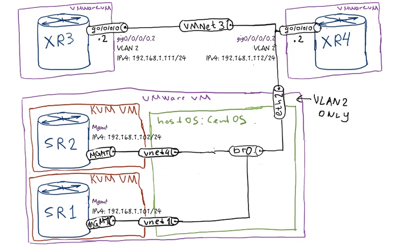
To show the real power of any kind of traffic engineering it’s good to have a lot of routers. Unfortunately, I don’t have it, but my laptop allows me to launch 4 virtual routers. Half of them are Nokia (Alcatel-Lucent) VSR and half of them are Cisco IOS XRv (XRv 9000) routers. The physical topology of virtual routers has the following structure:
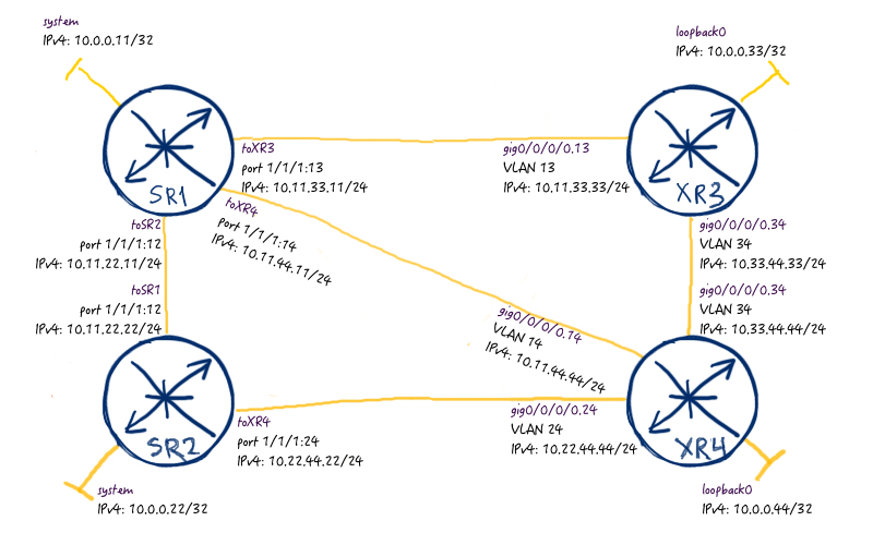
For the logical topology I’ll deploy partial mesh, so that I have a lot of possibilities to send the traffic between PEs:
As a IGP in this network I’ll used ISIS, just because I like ISIS more than OPSF, but you can easily replace it, if you like. The most important point is that all links have the same cost, so you could easily identify routing patterns in the network.
The initial configurations files are available here:
We don’t stay here for a long check, just briefly screen that ISIS propagate label SR information that is label block, index and adjacency labels. For variety we’ll check how ISIS LSP look like at Nokia VSR side:
A:SR2# show router isis database SR1.00-00 detail
===============================================================================
Rtr Base ISIS Instance 0 Database (detail)
===============================================================================
Displaying Level 2 database
——————————————————————————-
LSP ID : SR1.00-00 Level : L2
Sequence : 0x15 Checksum : 0x7bf9 Lifetime : 957
Version : 1 Pkt Type : 20 Pkt Ver : 1
Attributes: L1L2 Max Area : 3 Alloc Len : 205
SYS ID : 0100.0000.0011 SysID Len : 6 Used Len : 205
====
TLVs :
. Area Addresses:
. Area Address : (3) 49.0000
. Supp Protocols:
. Protocols : IPv4
. IS-Hostname : SR1
. Router ID :
. Router ID : 10.0.0.11
. Router Cap : 10.0.0.11, D:0, S:0
. TE Node Cap : B E M P
. SR Cap: IPv4 MPLS-IPv6 . SRGB Base:500000, Range:20000 . SR Alg: metric based SPF
. I/F Addresses :
. I/F Address : 10.0.0.11
. I/F Address : 10.11.22.11
. I/F Address : 10.11.33.11
. I/F Address : 10.11.44.11
. TE IS Nbrs :
. Nbr : SR2.00
. Default Metric : 10
. Sub TLV Len : 19
. IF Addr : 10.11.22.11
. Nbr IP : 10.11.22.22 . Adj-SID: Flags:v4VL Weight:0 Label:262143
. TE IS Nbrs :
. Nbr : XR3.00
. Default Metric : 10
. Sub TLV Len : 19
. IF Addr : 10.11.33.11
. Nbr IP : 10.11.33.33 . Adj-SID: Flags:v4VL Weight:0 Label:262142
. TE IS Nbrs :
. Nbr : XR4.00
. Default Metric : 10
. Sub TLV Len : 19
. IF Addr : 10.11.44.11
. Nbr IP : 10.11.44.44 . Adj-SID: Flags:v4VL Weight:0 Label:262141
. TE IP Reach :
. Default Metric : 0
. Control Info: S, prefLen 32
. Prefix : 10.0.0.11 . Sub TLV : . Prefix-SID Index:11, Algo:0, Flags:NnP
You might spot interesting difference, that Cisco IOS XR allocates 2 labels for interconnect link, whereas Nokia allocates only one.
More information about Segment Routing configuration and verification you can find in the corresponding article.
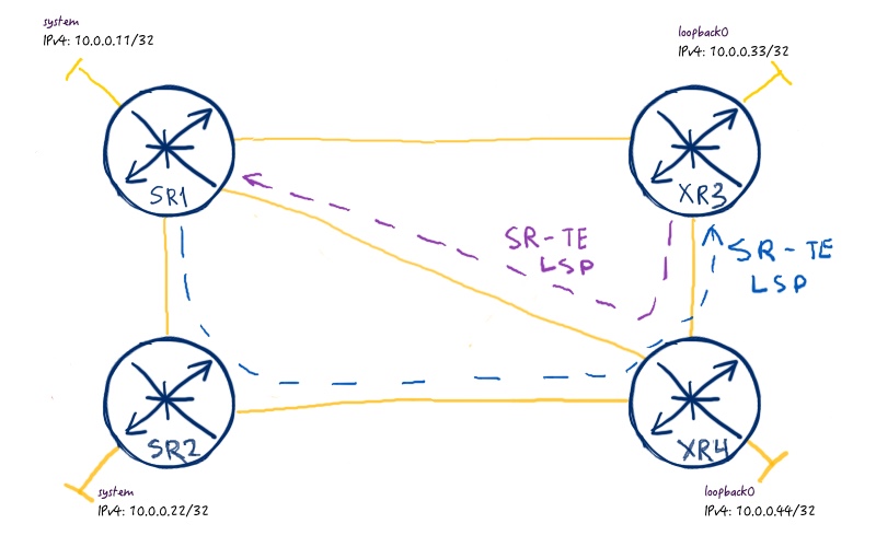
After Segment Routing is enabled and labels are propagated, we come to the most interesting part of this article, where we deploy SR TE. The scenario is the following:
Traffic from SR1 (Nokia SR OS routers) to XR3 (Cisco IOS XR router) should follow path SR1 -> SR2 -> XR3 -> XR4.
Traffic from XR3 to SR1 should go XR3 -> XR4 -> SR1
To better understand that scenario, see the scheme below:
First of all we need to enable MPLS TE support, as Segment Routing TE uses TED (traffic engineering database):
Nokia (Alcatel-Lucent) SR OS
Cisco IOS XR
SR1
XR3
A:SR1>edit-cfg# candidate view
=========================
configure
router
mpls
interface “system”
no shutdown
exit
interface “toSR2”
no shutdown
exit
interface “toXR3”
no shutdown
exit
interface “toXR4”
no shutdown
exit
no shutdown
exit
rsvp
no shutdown
exit
isis
traffic-engineering
exit
exit
exit
=========================
The first interesting difference is that in Nokia (Alcatel-Lucent) SR OS you have to enable both MPLS TE and RSVP in order to get MPLS TE information generated (in order TED to be populated in other words). In Cisco IOS XR you need enable only MPLS TE. Let’s check briefly the content of newly build MPLS TED:
Though this output might seem to long, it shows that all our routers has links to each other in TED so that it’s full and can be used for LSP build.
Now we proceed the configuration of SR TE tunnels :
Nokia (Alcatel-Lucent) SR OS
Cisco IOS XR
SR2
XR3
A:SR1>edit-cfg# candidate view
=========================
configure
router
mpls
path “EP_SR_SR1_SR2_XR4_XR3”
hop 10 10.0.0.22 strict
hop 20 10.0.0.44 strict
hop 30 10.0.0.33 strict
no shutdown
exit
lsp “SR1_TO_XR3” sr-te
to 10.0.0.33
cspf
primary “EP_SR_SR1_SR2_XR4_XR3”
exit
no shutdown
exit
exit
exit
=========================
RP/0/0/CPU0:XR3(config)#show conf
!
explicit-path name ECP_SR_XR3_XR4_SR1
index 10 next-address strict ipv4 unicast 10.0.0.44
index 20 next-address strict ipv4 unicast 10.0.0.11
!
interface tunnel-te1031
ipv4 unnumbered Loopback0
autoroute announce
!
destination 10.0.0.11
record-route
path-option 10 explicit name ECP_SR_XR3_XR4_SR1 segment-routing
!
end
Now we have 2 SR TE tunnels. From the configuration point of view, you see that we define next-hop routers in a strict fashion, and we say nothing about labels. Pay attention that in Nokia (Alcatel-Lucent) SR OS we define specific LSP type “sr-te” upon LSP creation, whereas in Cisco IOS XR we define segment routing in “path-option”. Let’s check which labels are used for this tunnels.
From Nokia SR OS router SR2 we have the following:
A:SR1# show router mpls sr-te-lsp “SR1_TO_XR3” detail path “EP_SR_SR1_SR2_XR4_XR3”
===============================================================================
MPLS SR-TE LSP SR1_TO_XR3 Path EP_SR_SR1_SR2_XR4_XR3 (Detail)
===============================================================================
Legend :
S – Strict L – Loose
===============================================================================
——————————————————————————-
SR-TE LSP SR1_TO_XR3 Path EP_SR_SR1_SR2_XR4_XR3
——————————————————————————-
LSP Name : SR1_TO_XR3
Path LSP ID : 38912
From : 10.0.0.11 To : 10.0.0.33
Admin State : Up Oper State : Up Path Name : EP_SR_SR1_SR2_XR4_XR Path Type : Primary
================================
Path Admin : Up Path Oper : Up
Path Up Time : 0d 00:17:40 Path Down Time : 0d 00:00:00
Retry Limit : 0 Retry Timer : 30 sec
Retry Attempt : 1 Next Retry In : 0 sec
================================
CSPF : Enabled Oper CSPF : Enabled
================================
Bandwidth : No Reservation Oper Bandwidth : 0 Mbps
Hop Limit : 255 Oper HopLimit : 255
Setup Priority : 7 Oper Setup Priority : 7
Hold Priority : 0 Oper Hold Priority : 0
Inter-area : N/A
================================
PCE Updt ID : 0 PCE Updt State : None
PCE Upd Fail Code: noError
================================
PCE Report : Inherited Oper PCE Report : Disabled
PCE Control : Disabled Oper PCE Control : Disabled
PCE Compute : Disabled
================================
Include Groups : Oper Include Groups :
None None
Exclude Groups : Oper Exclude Groups :
None None
================================
IGP/TE Metric : 16777215 Oper Metric : 16777215
Oper MTU : 1488 Path Trans : 1
Failure Code : noError
Failure Node : n/a Explicit Hops : . 10.0.0.22(S) -> 10.0.0.44(S) -> 10.0.0.33(S) Actual Hops : . 10.11.22.22 (10.0.0.22) Record Label : 262143
.-> 10.22.44.44 (10.0.0.44) Record Label : 262142 .-> 10.33.44.33 (10.0.0.33) Record Label : 24008
===============================================================================
!
!
A:SR1# show router fp-tunnel-table 1
===============================================================================
Tunnel Table Display
Legend:
B – FRR Backup
===============================================================================
Destination Protocol Tunnel-ID
. Lbl NextHop Intf/Tunnel
——————————————————————————-
10.0.0.22/32 SR-ISIS-0 –
. 500022 10.11.22.22 1/1/1:12
10.0.0.33/32 SR-ISIS-0 –
. 3 10.11.33.33 1/1/1:13 10.0.0.33/32 SR-TE – . 24008/262142 10.11.22.22 SR
10.0.0.44/32 SR-ISIS-0 –
. 3 10.11.44.44 1/1/1:14
10.11.22.22/32 SR –
. 3 10.11.22.22 1/1/1:12
10.11.33.33/32 SR –
. 3 10.11.33.33 1/1/1:13
10.11.44.44/32 SR –
. 3 10.11.44.44 1/1/1:14
——————————————————————————-
Total Entries : 7
——————————————————————————-
===============================================================================
So this output says, if we use this SR-TE LSP, we send traffic to next-hop 10.11.22.22 (SR2) with two labels in stack: topmost is 262142 and bottom transport label is 24008. Both of these labels differ from Segment Routing block (16000 – 23999 is default for for Cisco IOS XR and we have configured 500000 – 519999 for Nokia SR OS). Seems strange? Well, these are adjacency labels for interconnected links (the output from ISIS LSDP is highly reduced):
A:SR1# show router isis database SR2.00-00 detail
==========================================================
LSP ID : SR2.00-00 Level : L2
Sequence : 0x1b Checksum : 0x37bc Lifetime : 1065
Version : 1 Pkt Type : 20 Pkt Ver : 1
Attributes: L1L2 Max Area : 3 Alloc Len : 283
SYS ID : 0100.0000.0022 SysID Len : 6
. TLVs :
. Area Addresses:
. Area Address : (3) 49.0000
. Supp Protocols:
. Protocols : IPv4
. IS-Hostname : SR2
. Router ID :
. Router ID : 10.0.0.22
. Router Cap : 10.0.0.22, D:0, S:0
. TE Node Cap : B E M P
. SR Cap: IPv4 MPLS-IPv6
. SRGB Base:500000, Range:20000
. !
. TE IS Nbrs : . Nbr : XR4.00
. ! . IF Addr : 10.22.44.11 . Nbr IP : 10.22.44.44 . !
. Adj-SID: Flags:v4VL Weight:0 Label:262143
==========================================================
!
!
A:SR1# show router isis database XR4.00-00 detail
==========================================================
LSP ID : XR4.00-00 Level : L2
Sequence : 0x14 Checksum : 0xa66 Lifetime : 1182
Version : 1 Pkt Type : 20 Pkt Ver : 1
Attributes: L1L2 Max Area : 0 Alloc Len : 481
SYS ID : 0100.0000.0044 SysID Len : 6
!
. TLVs :
. Area Addresses:
. Area Address : (3) 49.0000
. Supp Protocols:
. Protocols : IPv4
. IS-Hostname : XR4
. I/F Addresses :
. I/F Address : 10.0.0.44
. Router ID :
. Router ID : 10.0.0.44
. Router Cap : 10.0.0.44, D:0, S:0
. SR Cap: IPv4
. SRGB Base:16000, Range:8000
. !
. TE IS Nbrs : . Nbr : XR3.00
. ! . IF Addr : 10.33.44.44 . Nbr IP : 10.33.44.33
. ! . Adj-SID: Flags:v4BVL Weight:0 Label:24008 . Adj-SID: Flags:v4VL Weight:0 Label:24009
==========================================================
Logic is quite simple:
When SR2 receives the packet with the topmost label 262142, it knows that it must pop it and send packet out to next hop 10.22.44.44
When XR4 receives the packer with the topmost label 24008, it knows that it must pop it and send packet out to next hop 10.33.44.33
When XR3 receives the rest of the packet, it will look into the MPLS service label, so no additional IP/MPLS lookup is needed
Let’s check Cisco IOS XR side now:
RP/0/0/CPU0:XR3#show mpls traffic-eng tunnels 1031
Name: tunnel-te1031 Destination: 10.0.0.11 Ifhandle:0x170
. Signalled-Name: XR3_t1031
. Status:
. Admin: up Oper: up Path: valid Signalling: connected . path option 10, (Segment-Routing) type explicit ECP_SR_XR3_XR4_SR1 (Basis for Setup)
. G-PID: 0x0800 (derived from egress interface properties)
. Bandwidth Requested: 0 kbps CT0
. Creation Time: Mon Jul 24 23:52:15 2017 (01:21:45 ago)
. Config Parameters:
. Bandwidth: 0 kbps (CT0) Priority: 7 7 Affinity: 0x0/0x0
. Metric Type: TE (global)
. Path Selection:
. Tiebreaker: Min-fill (default)
. Protection: any (default)
. Hop-limit: disabled
. Cost-limit: disabled
. Path-invalidation timeout: 10000 msec (default), Action: Tear (default)
. AutoRoute: enabled LockDown: disabled Policy class: not set
. Forward class: 0 (default)
. Forwarding-Adjacency: disabled
. Autoroute Destinations: 0
. Loadshare: 0 equal loadshares
. Auto-bw: disabled
. Path Protection: Not Enabled
. BFD Fast Detection: Disabled
. Reoptimization after affinity failure: Enabled
. SRLG discovery: Disabled
. History:
. Tunnel has been up for: 01:10:32 (since Tue Jul 25 00:03:28 UTC 2017)
. Current LSP:
. Uptime: 01:10:32 (since Tue Jul 25 00:03:28 UTC 2017)
. Reopt. LSP:
. Last Failure:
. LSP not signalled, identical to the [CURRENT] LSP
. Date/Time: Tue Jul 25 00:51:00 UTC 2017 [00:23:00 ago]
. Prior LSP:
. ID: 2 Path Option: 10
. Removal Trigger: tunnel shutdown
. Segment-Routing Path Info (IS-IS CORE level-2) . Segment0[Node]: 10.0.0.44, Label: 16044 . Segment1[Node]: 10.0.0.11, Label: 16011
!
!
RP/0/0/CPU0:XR3#show cef ipv4 10.0.0.11/32
10.0.0.11/32, version 200, internal 0x1000001 0x81 (ptr 0xa14077f4) [1], 0x0 (0xa13d3464), 0xa28 (0xa1583230)
.Updated Jul 25 00:03:28.834
.Prefix Len 32, traffic index 0, precedence n/a, priority 1 . via 10.0.0.11/32, tunnel-te1031, 7 dependencies, weight 0, class 0 [flags 0x0]
. path-idx 0 NHID 0x0 [0xa10e41a8 0x0]
. next hop 10.0.0.11/32
. local adjacency . labels imposed {500011}
Cisco unfortunately doesn’t show directly all the label stack if we have to deal with MPLS TE tunnels, so we need to combine these two ouputs.
Cisco IOS XR is much easier than Nokia SR OS in terms of checking MPLS TE as you can use TE tunnel for all traffic, not only to services.
Keeping in mind the tip above, let’s test TE tunnel:
RP/0/0/CPU0:XR3#traceroute 10.0.0.11 so 10.0.0.33
Tracing the route to 10.0.0.11
1 10.33.44.44 [MPLS: Labels 16011/500011 Exp 0] 9 msec 0 msec 0 msec
2 10.0.0.11 0 msec 9 msec 0 msec
Nokia (Alcatel-Lucent) SR OS and Cisco IOS XR (actually, IOS / IOS XE / NX-OS) behaves in different fashion regarding PHP. Cisco has it by default and Nokia doesn’t have. Based on that fact, we have 2 labels in label stack as well:
When XR4 receives the packet with the topmost label 16011, it swaps this label and send packet to next hop 10.11.44.11
When XR1 receives the packet with the topmost label 500011, it removes this label and make the next IP/MPLS lookup to understand, what to do with the traffic further.
Verification of Segment Routing Traffic Engineering
To show you these packets in live I’ll configure simple BGP/MPLS IP VPN between SR1 and XR3 to make use of these SR-TE tunnels. I don’t provide configuration for brevity, just one output per device. Nokia VSR:
A:SR1# show router 10 route-table
===============================================================================
Route Table (Service: 10)
===============================================================================
Dest Prefix[Flags] Type Proto Age Pref
. Next Hop[Interface Name] Metric
——————————————————————————-
192.168.11.11/32 Local Local 00h05m56s 0
. TEST 0
192.168.33.33/32 Remote BGP VPN 00h00m07s 170
. 10.0.0.33 (tunneled:SR-TE:655362)
===============================================================================
Cisco XRv 9000:
RP/0/0/CPU0:XR3#show route vrf TEST ipv4
B 192.168.11.11/32 [200/0] via 10.0.0.11 (nexthop in vrf default), 00:07:12
L 192.168.33.33/32 is directly connected, 00:04:30, Loopback1
Now let’s make ping test and make Wireshark snapshot.
RP/0/0/CPU0:XR3#ping vrf TEST 192.168.11.11 so 192.168.33.33
Sending 5, 100-byte ICMP Echos to 192.168.11.11, timeout is 2 seconds:
!!!!!
Success rate is 100 percent (5/5), round-trip min/avg/max = 1/7/9 ms
What is very interesting in the output above is that label stack in way from XR3 to SR1 has only 2 labels instead of 3. If we think a minute and see my explanation above, it should be 3 labels (16011 / 500011 / BGP Label). But when XR4 makes swap 16011 to 500011, it would then (500011 / 500011 / BGP Label), what is obviously not efficient. I see this packet dump for the first time myself, but I find it cool that there is such kind of label stack optimisation in place.
Conclusion
SDN is slowly coming in SP world and we need to understand not only how it work, but also how we can benefit from it. Evolution of Segment Routing to SR TE gives you possibility to have single protocol for all kind of the routing. BUT (hello, Frank :-)) it makes sense only if the network has such kind of demand or topology, where traffic engineering is necessary. Each technology is only as good as the business case it’s driven by. SR TE is evolving set right now and there are numerous limitations now (like absence of BW reservation of lack of MVPN support), but I’ m sure it’s only temporary issue and the solution will be developed soon. Take care and good bye!