SDN sandbox 3. Unnumbered Ethernet interface in Nokia SR OS and Cisco IOS XR. Part 1.
Anton Karneliuk
Hello my friend,
One of my friends said that he has started implementing on Cisco routers one interesting feature that is subject of the article. Then I have found its description in slides from Cisco Live 2017. I decided to dig into it deeper and see how interoperable it is. Some results are unexpected.
1 2 3 4 5
No part of this blogpost could be reproduced, stored in a
retrieval system, or transmitted in any form or by any
means, electronic, mechanical or photocopying, recording,
or otherwise, for commercial purposes without the
prior permission of the author.
Disclaimer
Information in this article is provided on “as-is” basis. I haven’t managed to achieve 100% interoperability between Nokia (Alcatel-Lucent) SR OS and Cisco IOS XR. What was unexpected for me is that Cisco has shown lower level of support their own features in router itself. I can imagine two possible causes for that. Either I haven’t configured something properly, or Cisco solution demands centralized controller for that. That will be checked in next articles.
Brief overview
The presentation that I mention is called BRKSPG-2518, you can search for it at CiscoLive website (link). It explains Cisco’s vision of network evolution beyond seamless MPLS deployment. I want to talk here about one particular feature that is usage of unnumbered Ethernet interfaces. In nutshell unnumbered interfaces aren’t something new and they were used for decades in serial links with HLDC/PPP encapsulation, termination of clients at BNG via PPPoE and so on. The main idea of unnumbered interfaces is that you don’t configure any specific IPv4/IPv6 address at interface but you rather say interface to use IP address from different interface, which is typically system for Nokia (Alcatel-Lucent) SR OS or loopback 0 in Cisco IOS XR. As loopback interface usually have 32-bit-length prefix for IPv4 and 128-bit-length for IPv6, usage of such address at interface changes the rules for routing protocols (IGP). Both OSPF and ISIS demands that IPv4 addresses at common link between two routers belong to the same subnet.
Well, let’s think for a moment about communication flow at point-to-point links. Initially the 30-bit-length prefix was used to provide such connectivity. Such prefix provide in total 4 IPv4 addresses, whereas only two of them (2nd and 3rd) can be used for addressing of the interface. 1st and 4th IPv4 addresses are network address and broadcast for this subnet and they can’t be used for interface addressing. It means that effectivity of IP address usage at point-to-point links were as low as 50%. Then in xxxx RFCXXXX (link) was issued that allowed to use 31-bit-length prefixes at point-to-point links, as there are only two hosts and there is no necessity to send broadcast neither have subnet address. It allowed ISPs across all the world to increase usage of IPv4 addresses at interconnects links up to 100% and provided a lot of free IPv4 addresses that can’t be used for customers or services.
As I mentioned earlier, for point-to-point encapsulations that is HLDC, PPP or point-to-point sub interfaces in Frame-Relay it was possible even to go further and make use of its loopback for interconnect interfaces. It means that you don’t need to lose ANY IPv4 address for interconnect links. For Ethernet it wasn’t possible as Ethernet isn’t considered to be point-to-point link, as it’s rather multi-access. Now it’s possible.
What does it mean? It means that at P routers you technically need ONLY ONE IP address. Well, from management prospective you might have more, but one IP address will be enough to make traffic forwarding between other P/PE devices. At PE/ASBR routers you might have still 30/31 prefix to the customers, but it also isn’t 100% needed. So, in time when we have lack of available public IPv4 addresses, we can reuse then from interconnect links as they aren’t needed there anymore.
What are we going to test?
I’m going to start with initial configuration from previous lab (link) and to convert that network to use unnumbered Ethernet interfaces. We’ll test IPv4/IPv6 forwarding and then we’ll test MPLS forwarding with LDP, RSVP/MPLS-TE and segment routing. To make use of MPLS data plane, we’ll create simple BGP/MPLS IP VPN (for IPv4/IPv6) and test connectivity of redesigned network.
Software version
For tests in this lab I use the following versions of software for routers:
Nokia (Alcatel-Lucent) SR OS 14.0.R4
Cisco IOS XRv 6.1.2
I haven’t used to mention it previously, though it’s very important to understand, which particular SW allows us to achieve the interoperability and which not.
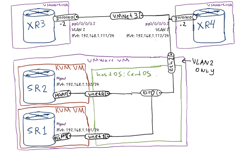
Topology
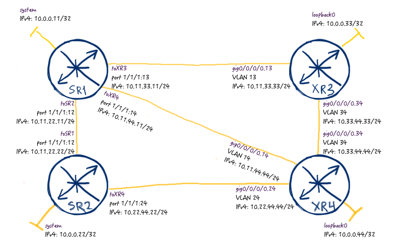
Our physical topology will be formed from 4 routers, 2 of them are Nokia (Alcatel-Lucent) VSR and two of them are Cisco IOS XRv:
As I’ve already mentioned before, we’ll use the topology from the previous lab as initial basis:
I’m intend to use the existing topology because it’s easy to compare the results, changes and so on with the previous lab to assess the changes. The only difference, I always say that you can use routing protocol whatever you like. This time it makes sense for you to start with ISIS as it’s provided in my config. You will see later on why.
Before we start, just brief check that connectivity between our nodes is up and running:
RP/0/0/CPU0:XR3#ping 10.0.0.11 so 10.0.0.33
Type escape sequence to abort.
Sending 5, 100-byte ICMP Echos to 10.0.0.11, timeout is 2 seconds:
!!!!!
Success rate is 100 percent (5/5), round-trip min/avg/max = 9/17/29 ms
!
!
RP/0/0/CPU0:XR3#ping 10.0.0.22 so 10.0.0.33
Type escape sequence to abort.
Sending 5, 100-byte ICMP Echos to 10.0.0.22, timeout is 2 seconds:
!!!!!
Success rate is 100 percent (5/5), round-trip min/avg/max = 1/9/19 ms
!
!
RP/0/0/CPU0:XR3#ping 10.0.0.33 so 10.0.0.33
Type escape sequence to abort.
Sending 5, 100-byte ICMP Echos to 10.0.0.33, timeout is 2 seconds:
!!!!!
Success rate is 100 percent (5/5), round-trip min/avg/max = 1/1/1 ms
!
!
RP/0/0/CPU0:XR3#ping 10.0.0.44 so 10.0.0.33
Type escape sequence to abort.
Sending 5, 100-byte ICMP Echos to 10.0.0.44, timeout is 2 seconds:
!!!!!
Success rate is 100 percent (5/5), round-trip min/avg/max = 1/1/1 ms
It looks so far good and now we can start. Today the core point is to change configuration of the Ethernet interfaces as unnumbered for IPv4:
Nokia (Alcatel-Lucent) SR OS
Cisco IOS XR
SR1
XR3
A:SR1>edit-cfg# candidate view
=========================
configure
router
interface “toSR2”
no address
unnumbered “system”
exit
interface “toXR3”
no address
unnumbered “system”
exit
interface “toXR4”
no address
unnumbered “system”
exit
exit
exit
=========================
RP/0/0/CPU0:XR3(config)#show conf
!
interface GigabitEthernet0/0/0/0.13
ipv4 point-to-point
no ipv4 address
ipv4 unnumbered Loopback0
!
interface GigabitEthernet0/0/0/0.34
ipv4 point-to-point
no ipv4 address
ipv4 unnumbered Loopback0
!
end
RP/0/0/CPU0:XR4(config)#show conf
!
interface GigabitEthernet0/0/0/0.14
ipv4 point-to-point
no ipv4 address
ipv4 unnumbered Loopback0
!
interface GigabitEthernet0/0/0/0.24
ipv4 point-to-point
no ipv4 address
ipv4 unnumbered Loopback0
!
interface GigabitEthernet0/0/0/0.34
ipv4 point-to-point
no ipv4 address
ipv4 unnumbered Loopback0
!
end
During the changes the configuration of the interfaces, the ISIS adjacency is continuously flapping. We haven’t configured logging at Nokia (Alcatel-Lucent) SR OS, that’s why we see the indication at Cisco IOS XR:
RP/0/0/CPU0:XR4(config)#RP/0/0/CPU0:Aug 4 18:16:09.471 : isis[1011]: %ROUTING-ISIS-6-INFO_STARTUP_FINISH : Cold controlled start completed
RP/0/0/CPU0:Aug 4 18:20:52.222 : isis[1011]: %ROUTING-ISIS-6-IIH_IF_ADDRESS : IIH received from GigabitEthernet0/0/0/0.34 SNPA 0050.5631.b773 contains unusable IPv4 interface address: 10.0.0.33 not on same subnet as local interface
RP/0/0/CPU0:Aug 4 18:20:52.222 : isis[1011]: %ROUTING-ISIS-5-ADJCHANGE : Adjacency to XR3 (GigabitEthernet0/0/0/0.34) (L2) Down, No common topology
!
!
RP/0/0/CPU0:XR4#RP/0/0/CPU0:Aug 4 18:25:08.104 : isis[1011]: %ROUTING-ISIS-5-ADJCHANGE : Adjacency to XR3 (GigabitEthernet0/0/0/0.34) (L2) Up, New adjacency
If you want to know how to enable and fine tune logging in Nokia (Alcatel-Lucent) SR OS or Cisco IOS XR, read the corresponding article.
As you see, just after we changes the interface configuration on side, we receive the syslog message that IPv4 address of the peering router isn’t in the common range so that the adjacency went down. Later, when we change the peer configuration as well, the ISIS peering went up.
The first check relates to the routing and ARP table, because both of them are critically important for connectivity. At Nokia (Alcatel-Lucent) SR OS router SR1 you see the following situations:
A:SR1# show router interface
===============================================================================
Interface Table (Router: Base)
===============================================================================
Interface-Name Adm Opr(v4/v6) Mode Port/SapId
. IP-Address PfxState
——————————————————————————-
system Up Up/Down Network system
. 10.0.0.11/32 n/a
toSR2 Up Up/Down Network 1/1/1:12
. Unnumbered If[system] n/a
toXR3 Up Up/Down Network 1/1/1:13
. Unnumbered If[system] n/a
toXR4 Up Up/Down Network 1/1/1:14
. Unnumbered If[system] n/a
——————————————————————————-
Interfaces : 4
===============================================================================
!
!
A:SR1# show router arp
===============================================================================
ARP Table (Router: Base)
===============================================================================
IP Address MAC Address Expiry Type Interface
——————————————————————————-
10.0.0.11 02:65:ff:00:00:00 00h00m00s Oth system
unnumbered fa:ac:a6:14:02:02 03h45m32s Dyn[I] toSR2
unnumbered fa:ac:a6:14:01:02 00h00m00s Oth[I] toSR2
unnumbered 00:50:56:31:b7:73 03h44m50s Dyn[I] toXR3
unnumbered fa:ac:a6:14:01:02 00h00m00s Oth[I] toXR3
unnumbered 00:50:56:23:d3:7e 03h44m45s Dyn[I] toXR4
unnumbered fa:ac:a6:14:01:02 00h00m00s Oth[I] toXR4
——————————————————————————-
No. of ARP Entries: 7
===============================================================================
Now we check the same tables at Cisco IOS XR router XR3:
RP/0/0/CPU0:XR3#show ipv4 interface brief
Interface IP-Address Status Protocol Vrf-Name
Loopback0 10.0.0.33 Up Up default
MgmtEth0/0/CPU0/0 unassigned Up Up default
GigabitEthernet0/0/0/0 unassigned Up Up default
GigabitEthernet0/0/0/0.13 10.0.0.33 Up Up default
GigabitEthernet0/0/0/0.34 10.0.0.33 Up Up default
!
!
RP/0/0/CPU0:XR3#show route ipv4
i L2 10.0.0.11/32 [115/10] via 10.0.0.11, 00:16:13, GigabitEthernet0/0/0/0.13
i L2 10.0.0.22/32 [115/20] via 10.0.0.11, 00:15:23, GigabitEthernet0/0/0/0.13
. [115/20] via 10.0.0.44, 00:15:23, GigabitEthernet0/0/0/0.34
L 10.0.0.33/32 is directly connected, 00:27:55, Loopback0
i L2 10.0.0.44/32 [115/10] via 10.0.0.44, 00:18:33, GigabitEthernet0/0/0/0.34
!
!
RP/0/0/CPU0:XR3# show arp
——————————————————————————-
0/0/CPU0
——————————————————————————-
Address Age Hardware Addr State Type Interface
10.0.0.33 – 0050.5631.b773 Interface ARPA GigabitEthernet0/0/0/0.13
10.0.0.33 – 0050.5631.b773 Interface ARPA GigabitEthernet0/0/0/0.34
10.0.0.44 00:18:54 0050.5623.d37e Dynamic ARPA GigabitEthernet0/0/0/0.34
169.254.0.2 00:16:24 faac.a614.0102 Dynamic ARPA GigabitEthernet0/0/0/0.13
This output shows very interesting difference between Nokia (Alcatel-Lucent) SR OS and Cisco IOS XR. Nokia (Alcatel-Lucent) VSR automatically generates prefix from IPv4 link-local range (169.254.0.0/16), whereas Cisco doesn’t do it. On the other hand, you can’t find this IPv4 address somewhere else.
The next check will be related the ISIS LSDP, where we see, what is distributed into LSP by different routers. The following output is grabbed from XR3:
You might spot that the LSP are generated in a bit different manner. Nokia (Alcatel-Lucent) SR OS extends information of adjacent ISIS by adding IDs of local/remote interfaces, whereas Cisco IOS XR doesn’t do it.
Now we can make some tests to check basic connectivity:
A:SR1# ping 10.0.0.11 count 1
PING 10.0.0.11 56 data bytes
64 bytes from 10.0.0.11: icmp_seq=1 ttl=64 time=0.413ms.
—- 10.0.0.11 PING Statistics —-
1 packet transmitted, 1 packet received, 0.00% packet loss
round-trip min = 0.413ms, avg = 0.413ms, max = 0.413ms, stddev = 0.000ms
!
!
A:SR1# ping 10.0.0.22 count 1
PING 10.0.0.22 56 data bytes
64 bytes from 10.0.0.22: icmp_seq=1 ttl=64 time=16.4ms.
—- 10.0.0.22 PING Statistics —-
1 packet transmitted, 1 packet received, 0.00% packet loss
round-trip min = 16.4ms, avg = 16.4ms, max = 16.4ms, stddev = 0.000ms
!
!
A:SR1# ping 10.0.0.33 count 1
PING 10.0.0.33 56 data bytes
64 bytes from 10.0.0.33: icmp_seq=1 ttl=255 time=7.46ms.
—- 10.0.0.33 PING Statistics —-
1 packet transmitted, 1 packet received, 0.00% packet loss
round-trip min = 7.46ms, avg = 7.46ms, max = 7.46ms, stddev = 0.000ms
!
!
A:SR1# ping 10.0.0.44 count 1
PING 10.0.0.44 56 data bytes
64 bytes from 10.0.0.44: icmp_seq=1 ttl=255 time=8.21ms.
—- 10.0.0.44 PING Statistics —-
1 packet transmitted, 1 packet received, 0.00% packet loss
round-trip min = 8.21ms, avg = 8.21ms, max = 8.21ms, stddev = 0.000ms
Configuration of unnumbered IPv6 interfaces
In IPv6 addressing we have something called link-local address (from range fe80::/13) which are automatically generates as soon as you enable any interface (including system/loopback) for IPv6 routing. It’s a must, because almost all protocols responsible for building IPv6 forwarding plane (OSPF/ISIS, PIM, ICMP and on) uses these IPv6 link-local address (LLA) for communication. Actually, it’s enough to configure IPv6 LLA manually or just say that interface is IPv6 enabled in Cisco and that’s it. As this is the specific range and it isn’t routable beyond this particular interface that’s why we can’t save any IP addresses as we don in IPv4.
Unnumbered Ethernet interfaces and MPLS data plane using LDP
Let’s see which implication on other technologies has such approach of interface configuration. First of we’ll configure LDP in our network and see how label propagation/mapping is done.
You see that next-hops look very strange. I’ve checked, there is no mapping to interface IDs in ISIS LSP, so it might be related to something different or be just the form of the placeholder. Nevertheless, it works. Now it’s turn of Cisco IOS XR router XR3 to show its details of LFIB:
RP/0/0/CPU0:XR3#show mpls forwarding
Local Outgoing Prefix Outgoing Next Hop Bytes
Label Label or ID Interface Switched
—— ———– —————— ———— ————— ————
24000 Pop 10.0.0.44/32 Gi0/0/0/0.34 10.0.0.44 530
24001 262143 10.0.0.11/32 Gi0/0/0/0.13 10.0.0.11 3560
24002 262142 10.0.0.22/32 Gi0/0/0/0.13 10.0.0.11 0
. 24001 10.0.0.22/32 Gi0/0/0/0.34 10.0.0.44 0
Here you see the next hop as it is meaning the unnumbered interface IPv4 address from another router.
BGP/MPLS IPv4/IPv6 VPN service on top
To check the established MPLS data plane we’ll create a simple L3 VPN to generate the traffic:
Nokia (Alcatel-Lucent) SR OS
Cisco IOS XR
SR1
XR3
A:SR1>edit-cfg# candidate view
=========================
configure
router
autonomous-system 10
bgp
next-hop-resolution
label-route-transport-tunnel
family vpn
resolution any
exit
exit
exit
group “iBGP”
peer-as 10
local-address “10.0.0.11”
family vpn-ipv4 vpn-ipv6
neighbor “10.0.0.33”
exit
exit
exit
exit
service
vprn “10” customer 1 create
route-distinguisher “10:10”
vrf-target “target:10:10”
interface “TEST” create
loopback
address “192.168.1.10/32”
ipv6
address “fc00::192:168:1:10/128”
exit
exit
auto-bind-tunnel
resolution any
exit
no shutdown
exit
exit
exit
=========================
More information about configuration of BGP/MPLS IP VPN in Nokia (Alcatel-Lucent) SR OS and Cisco IOS XR you can find in the dedicated article.
We check the routing tables in corresponding VRF/VPRN and see how the tables ae populated.
Nokia (Alcatel-Lucent) VSR (SR 7750) router SR1:
A:SR1# show router 10 route-table
===============================================================================
Route Table (Service: 10)
===============================================================================
Dest Prefix[Flags] Type Proto Age Pref
. Next Hop[Interface Name] Metric
——————————————————————————-
192.168.1.10/32 Local Local 00h07m52s 0
. TEST 0
192.168.4.10/32 Remote BGP VPN 00h07m48s 170
. 10.0.0.33 (tunneled) 0
——————————————————————————-
No. of Routes: 2
Flags: n = Number of times nexthop is repeated
. B = BGP backup route available
. L = LFA nexthop available
. S = Sticky ECMP requested
===============================================================================
Cisco IOS XRv 9000 (ASR 9000) side is represented by XR3:
RP/0/0/CPU0:XR3#show route vrf TEST ipv4
Codes: C – connected, S – static, R – RIP, B – BGP, (>) – Diversion path
. D – EIGRP, EX – EIGRP external, O – OSPF, IA – OSPF inter area
. N1 – OSPF NSSA external type 1, N2 – OSPF NSSA external type 2
. E1 – OSPF external type 1, E2 – OSPF external type 2, E – EGP
. i – ISIS, L1 – IS-IS level-1, L2 – IS-IS level-2
. ia – IS-IS inter area, su – IS-IS summary null, * – candidate default
. U – per-user static route, o – ODR, L – local, G – DAGR, l – LISP
. A – access/subscriber, a – Application route
. M – mobile route, r – RPL, (!) – FRR Backup path
Gateway of last resort is not set
B 192.168.1.10/32 [200/0] via 10.0.0.11 (nexthop in vrf default), 00:09:52
L 192.168.4.10/32 is directly connected, 00:16:42, Loopback10
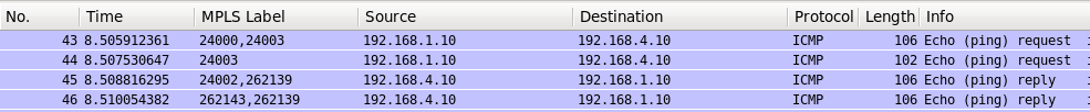
To make more interesting Wireshark oouput between SR1 and XR3 we’ll break the direct links and use another path. According to our topology we should see the following paths:
Forward path is SR1 -> XR4 -> XR3;
Backward path is XR3 – > XR4 -> SR1;
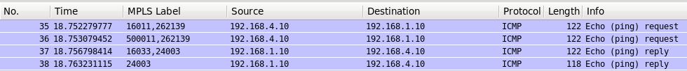
We make a ping and capture traffic in Wireshark. For IPv4 it looks like the following:
A:SR1# ping router 10 192.168.4.10
PING 192.168.4.10 56 data bytes
64 bytes from 192.168.4.10: icmp_seq=1 ttl=255 time=8.58ms.
64 bytes from 192.168.4.10: icmp_seq=2 ttl=255 time=6.87ms.
64 bytes from 192.168.4.10: icmp_seq=3 ttl=255 time=3.96ms.
64 bytes from 192.168.4.10: icmp_seq=4 ttl=255 time=10.2ms.
64 bytes from 192.168.4.10: icmp_seq=5 ttl=255 time=6.89ms.
—- 192.168.4.10 PING Statistics —-
5 packets transmitted, 5 packets received, 0.00% packet loss
round-trip min = 3.96ms, avg = 7.30ms, max = 10.2ms, stddev = 2.09ms
Wireshark output for IPv4:
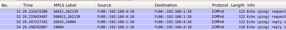
And for IPv6:
A:SR1# ping router 10 fc00::192:168:4:10
PING fc00::192:168:4:10 56 data bytes
64 bytes from fc00::192:168:4:10 icmp_seq=1 hlim=64 time=8.19ms.
64 bytes from fc00::192:168:4:10 icmp_seq=2 hlim=64 time=8.88ms.
64 bytes from fc00::192:168:4:10 icmp_seq=3 hlim=64 time=8.11ms.
64 bytes from fc00::192:168:4:10 icmp_seq=4 hlim=64 time=5.39ms.
64 bytes from fc00::192:168:4:10 icmp_seq=5 hlim=64 time=21.6ms.
—- fc00::192:168:4:10 PING Statistics —-
5 packets transmitted, 5 packets received, 0.00% packet loss
round-trip min = 5.39ms, avg = 10.4ms, max = 21.6ms, stddev = 5.70ms
Wireshark output for IPv6:
You see it’s working without problems. So the solution with unnumbered Ethernet interfaces is looking very promising so far.
Unnumbered Ethernet interfaces and MPLS data plane using Segment Routing
I’ve found the information about such interfaces configuration in context of Cisco SDN with Segment Routing, so it definitely should work. Let’s convert our MPLS data plane from LDP-based to Segment Routing based:
Nokia (Alcatel-Lucent) SR OS
Cisco IOS XR
SR1
XR3
A:SR1>edit-cfg# candidate view
=========================
configure
router
ldp
shutdown
exit
no ldp
mpls-labels sr-label start 500000 end 520000
isis
advertise-router-capability as
segment-routing
tunnel-table-pref 8
prefix-sid-range global
no shutdown
exit
interface “system”
ipv4-node-sid index 11
exit
exit
exit
exit
=========================
RP/0/0/CPU0:XR3(config)#show conf
!
router isis CORE
address-family ipv4 unicast
segment-routing mpls
no mpls ldp auto-config
!
interface Loopback0
address-family ipv4 unicast
prefix-sid index 33
!
!
!
no mpls ldp
end
SR2
XR4
A:SR2>edit-cfg# candidate view
=========================
configure
router
ldp
shutdown
exit
no ldp
mpls-labels sr-label start 500000 end 520000
isis
advertise-router-capability as
segment-routing
tunnel-table-pref 8
prefix-sid-range global
no shutdown
exit
interface “system”
ipv4-node-sid index 22
exit
exit
exit
exit
=========================
More information about Segment Routing configuration in Nokia (Alcatel-Lucent) SR OS and Cisco IOS XR you can find in the dedicated article.
Though it isn’t necessary I deconfigure LDP in order to have clear setup with one protocol that forms MPLS data plane. We won’t spend a lot of time on checking the data plane. Rather we’ll focus only on LFIB. First of all let’s check the information at SR1, which is Nokia (Alcatel-Lucent) VSR (SR 7750):
Here is another PE XR4, which is Cisco IOS XRv 9000 (ASR 9000):
RP/0/0/CPU0:XR3#show mpls forwarding
Local Outgoing Prefix Outgoing Next Hop Bytes
Label Label or ID Interface Switched
—— ———– —————— ———— ————— ————
16011 16011 SR Pfx (idx 11) Gi0/0/0/0.34 10.0.0.44 107
16022 16022 SR Pfx (idx 22) Gi0/0/0/0.34 10.0.0.44 0
16044 Pop SR Pfx (idx 44) Gi0/0/0/0.34 10.0.0.44 0
24003 Aggregate TEST: Per-VRF Aggr[V] \
. TEST 880
24004 Aggregate TEST: Per-VRF Aggr[V] \
. TEST 1080
24005 Pop SR Adj (idx 1) Gi0/0/0/0.34 10.0.0.44 0
24006 Pop SR Adj (idx 3) Gi0/0/0/0.34 10.0.0.44 0
We see the Segment Routing labels right now in LFIB in for both routers.
Now we check, how customer traffic is transmitted over the network. This time we do it from Cisco IOS XR router XR3:
RP/0/0/CPU0:XR3#ping vrf TEST 192.168.1.10 so 192.168.4.10
Type escape sequence to abort.
Sending 5, 100-byte ICMP Echos to 192.168.1.10, timeout is 2 seconds:
!!!!!
Success rate is 100 percent (5/5), round-trip min/avg/max = 1/9/19 ms
Wireshark output for IPv4:
For IPv6:
RP/0/0/CPU0:XR3#ping vrf TEST fc00::192:168:1:10 so fc00::192:168:4:10
Type escape sequence to abort.
Sending 5, 100-byte ICMP Echos to fc00::192:168:1:10, timeout is 2 seconds:
!!!!!
Success rate is 100 percent (5/5), round-trip min/avg/max = 9/15/19 ms
Wireshark output for IPv6:
Such solution is also working, what is definitely good. Let’s move forward.
Unnumbered Ethernet interfaces and MPLS data plane using Segment Routing Traffic Engineering
No we have come to the very important part of the article. We have identified previously that best-efforts routing (we don’t influence path selection) works without problem. Now we want to add traffic engineering support:
Critical point up to now. Cisco IOS XR (version 6.1.2) doesn’t populate TED if we use unnumbered Ethernet interface and ISIS as IGP. It means that we won’t be able to build SR TE LSP, because CSPF can’t be performed. In the same time Nokia (Alcatel-Lucent) SR OS populates TED without problems and/or additional configuration.
This time it’s important stick to a certain IGP, as I’ve said in the very beginning. In the next article we’ll play with additional staff to see what and how we can fix. I’ve just occasionally found that behavior of Cisco in ISIS and OSPF relating this case very different. And I spot it just because it didn’t work for me in ISIS. It means that probably some of my previous articles written on top of ISIS might not work for OSPF and vice versa. I If you find such caveats, please, let me know.
Conclusion
Initially I was thinking to cover everything in one article, but it’s already 24 pages in Word (where I’m writing it) so it would be definitely long to read. So I decided to split the article in two, and we’ll talk in the next chapter about SR-TE and RSVP/MPLS-TE in conjunction with unnumbered Ethernet interfaces. We speak about brand new technologies and concepts that are being developed just right now, so I assume there will be fixes for that. Probably I have missed something in configuration in Cisco IOS XR as there is still no clear documentation, even official configuration guide doesn’t provide answers. But in any case I’m very excited, because two cases are working and in case you don’t need MPLS TE, you can start profit from that approach right now. Take care and good bye!