SDN sandbox 5. PCEP and XTC for Nokia SR OS and Cisco IOS XR.
Anton Karneliuk
Hello my friend,
Continuing our journey in SDN world we reach the point, where we use external controller to compute the MPLS LSP. As a controller I’ve taken built-in functionality in IOS XR that is called XTC (XR Traffic Controller). Let’s see what has happened.
1 2 3 4 5
No part of this blogpost could be reproduced, stored in a
retrieval system, or transmitted in any form or by any
means, electronic, mechanical or photocopying, recording,
or otherwise, for commercial purposes without the
prior permission of the author.
Brief overview
Logically we continue the previous article about BGP-LS, where we export ISIS LSDB through BGP to external SDN controller emulated either by Nokia (Alcatel-Lucent) VSR or by Cisco IOS XRv. The idea now is to use this distributed information (actually TED – traffic engineering database) to calculate best path and instruct PE routers how to build MPLS LSP between each other.
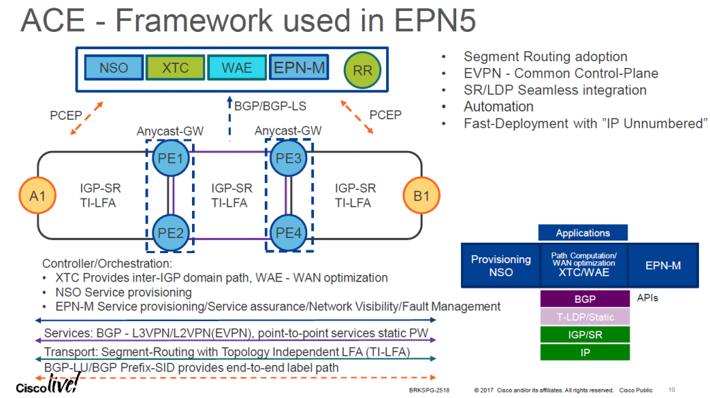
Explained task is clear case for SDN controller functionality. Both Nokia (Alcatel-Lucent) and Cisco Systems has some part of such functionality in their software of the router. You’ve just seen in the beginning that Cisco calls such product XTC (XR Traffic Controller) as it’s part of the Cisco IOS XR operating system. In presentation from Cisco Live this XTC is a core component of Cisco SDN:
On southbound interface it uses BGP-LS to grab routing topology and PCEP (Path Computation Element Protocol) to control MPLS LSPs at PE;
On northbound interface it uses Netconf/YANG, XML or something other to communicate and get back instructions from NSO Tail-f so that MPLS LSPs are build and visualized properly
More information about Cisco SDN solution for service providers are available in Cisco presentation at Cisco Live.
(c) Cisco
Unfortunately, there is very small amount of information about configuration of XTC in official sources. I’ve read a couple of articles on the other blogs, I will provide references later on in the article.
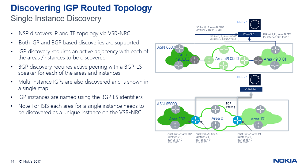
The last week I’ve also got information that Nokia (or plans to have) similar product that is called VSR-NRC (NRC stands for Network Resource Controller). Actually it does the same as XTC:
On southbound interface it uses BGP-LS to grab routing topology and PCEP (Path Computation Element Protocol) to control MPLS LSPs at PE;
On northbound interface it uses CPROTO to communicate with part of NSP (Network Service Platform) that is called NRC-P (Network Resource Controller for Packets). NSP is Nokia’s (Alcatel-Lucent) OSS previously called 5620 SAM
(c) Nokia
Both for Nokia (Alcatel-Lucent) VSR-NRC and for Cisco XTC we mention only BGP-LS and PCEP, though they support all variety of IGPs (ISIS and OSPF). We do it intentionally, because BGP-LS gives us much more flexibility and scalability than deployment of IGP.
The one difference between Nokia (Alcatel-Lucent) VSR-NRC and Cisco XTC is that VSR-NRC is licensed separately and you need the license to have this functionality working, whereas XTC is available without limitations even in XRv.
As you might understand from the images about, both Nokia VSR-NRC and Cisco XTC are part of SDN controller. I don’t say that these products are SDN controllers themselves as a lot of necessary functionality comes from OSS (NSP for Nokia and NSO for Cisco).
What are we going to test?
In this article we’ll configure Cisco IOS XRv (ASR 9000) as XTC, which is actually SDN controller, and connect two PEs (one Nokia (Alcatel-Lucent) SR OS router and one Cisco IOS XR router) to it. XTC should calculate MPLS LSP between these routers and instruct them how to talk to establish it.
Software version
For tests in this lab I use the following versions of software for routers:
Nokia (Alcatel-Lucent) SR OS 14.0.R4 (on SR2)
Nokia (Alcatel-Lucent) SR OS 15.0.R4 (on SR1)
Cisco IOS XRv 6.1.2
Since last article I’ve updated the version of SR OS from 15.0.R2 to 15.0.R4. Thanks Greg for supporting me.
Topology
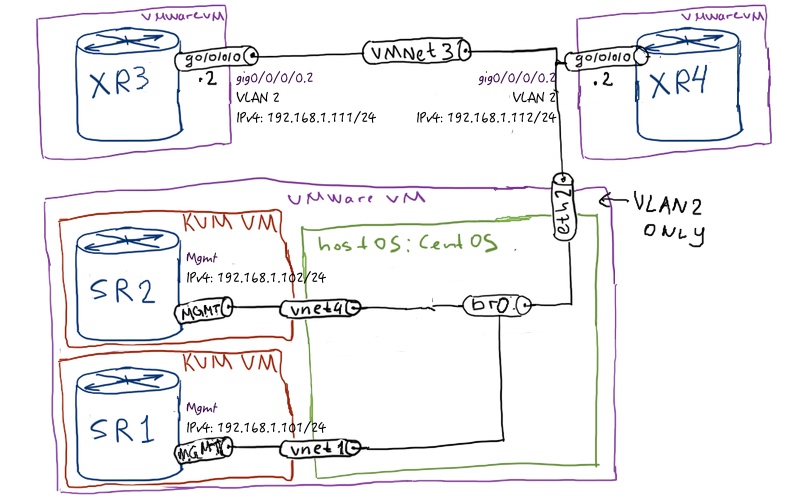
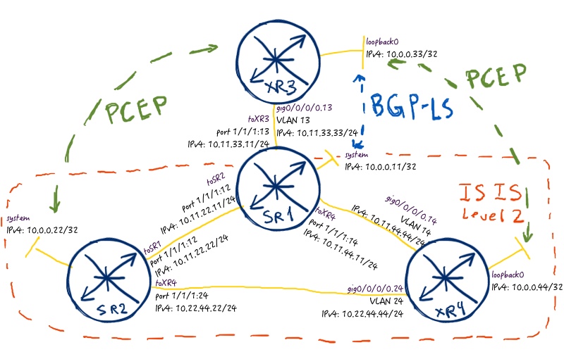
The physical topology is the same as I used for all my labs:
Actually, configuration of Cisco XTC is covered by mystery, because I haven’t managed to find something valuable neither in configuration guides nor in Cisco Live presentations. The only reference I’ve met in a blog. As I said initially, Cisco XTC is supposed to be controlled by NSO, and that might explain, why have almost no options for configuration of PCE locally. Here is our configuration of XTC:
XR3
RP/0/0/CPU0:XR3#show run
!
pce
address ipv4 10.0.0.33
logging no-path
!
segment-routing
!
end
Now we can check, which information is available for XTC to build proper MPLS tunnels:
RP/0/0/CPU0:XR3#show pce ipv4 topology
PCE’s topology database:
————————
Node 1
. TE router ID: 10.0.0.11
. ISIS system ID: 0100.0000.0011 level-2 domain ID: 10
. Prefix SID:
. Prefix 10.0.0.11, label 11 (regular)
.
. Link[0]: local address 10.11.22.11, remote address 10.11.22.22
. Local node:
. ISIS system ID: 0100.0000.0011 level-2 domain ID: 10
. Remote node:
. TE router ID: 10.0.0.22
. ISIS system ID: 0100.0000.0022 level-2
. Metric: IGP 10, TE 0
. Bandwidth: Total link 0, Reservable 0
. Adj SID: 262143 (unprotected)
.
. Link[1]: local address 10.11.44.11, remote address 10.11.44.44
. Local node:
. ISIS system ID: 0100.0000.0011 level-2 domain ID: 10
. Remote node:
. ISIS system ID: 0100.0000.0044 level-2
. Metric: IGP 10, TE 0
. Bandwidth: Total link 0, Reservable 0
. Adj SID: 262139 (unprotected)
.
Node 2
. TE router ID: 10.0.0.22
. ISIS system ID: 0100.0000.0022 level-2 domain ID: 10
. Prefix SID:
. Prefix 10.0.0.22, label 22 (regular)
.
. Link[0]: local address 10.11.22.22, remote address 10.11.22.11
. Local node:
. ISIS system ID: 0100.0000.0022 level-2 domain ID: 10
. Remote node:
. TE router ID: 10.0.0.11
. ISIS system ID: 0100.0000.0011 level-2
. Metric: IGP 10, TE 0
. Bandwidth: Total link 0, Reservable 0
. Adj SID: 262142 (unprotected)
.
. Link[1]: local address 10.22.44.22, remote address 10.22.44.44
. Local node:
. ISIS system ID: 0100.0000.0022 level-2 domain ID: 10
. Remote node:
. ISIS system ID: 0100.0000.0044 level-2
. Metric: IGP 10, TE 0
. Bandwidth: Total link 0, Reservable 0
. Adj SID: 262141 (unprotected)
.
Node 3
. ISIS system ID: 0100.0000.0044 level-2 domain ID: 10
. Prefix SID:
. Prefix 10.0.0.44, label 44 (regular)
.
. Link[0]: local address 10.11.44.44, remote address 10.11.44.11
. Local node:
. ISIS system ID: 0100.0000.0044 level-2 domain ID: 10
. Remote node:
. TE router ID: 10.0.0.11
. ISIS system ID: 0100.0000.0011 level-2
. Metric: IGP 10, TE 0
. Bandwidth: Total link 0, Reservable 0
. Adj SID: 24005 (protected) 24006 (unprotected)
.
. Link[1]: local address 10.22.44.44, remote address 10.22.44.22
. Local node:
. ISIS system ID: 0100.0000.0044 level-2 domain ID: 10
. Remote node:
. TE router ID: 10.0.0.22
. ISIS system ID: 0100.0000.0022 level-2
. Metric: IGP 10, TE 0
. Bandwidth: Total link 0, Reservable 0
. Adj SID: 24007 (protected) 24016 (unprotected)
Let’s move on and see how this information can be used.
Configuration of PCEP
In PCE terminology we have two types of nodes:
PCE, what stands for path computation element, and what is actually the server that performs the LSP computation.
PCC, what stands for PCE client, and what is PE router in our case that requests PCE to build an MPLS LSP for delegates control to it
As usual there are numerous options available for deployment:
PCC-initiated and PCC-controlled MPLS LSP, where all calculations of the paths are done locally and PCE is only informed about existing tunnel
PCC-initiated and PCE-controlled MPLS LSP, where PCC initiates the creation of MPLS LSP but then overtakes its management to PCE
PCE-initiated and PCE-controlled MPLS LSP, where all the stuff is done by PCE controller
Let’s configure PCC at SR2 and XR4 and connect them to PCE XR3 (XTC):
At SR1 there is no PCEP-related configuration and all we do is just export static route to our SDN controller (Cisco XTC) into ISIS so that other routers can reach that. At XR3 we deploy the reverse routes.
We don’t deploy default route at XR3, because routing table is used not only for routing but also for next-hop lookup for BGP. By default Cisco doesn’t use default route for BGP next-hop lookup, so we need either update the policy or create a proper route, what is easier.
At our PE routers SR2 and XR4 we only configure PCC part.
As logging is enabled by default at Cisco IOS XR routers, we see the following log messages at our Cisco XTC, which is XR3 in our topology:
RP/0/0/CPU0:XR3#RP/0/0/CPU0:Aug 5 21:04:51.218 : pce_server[1118]: %OS-PCE-5-PEER_STATE_CHANGE : PCEP Peer 10.0.0.44 state changed from Down to Up
RP/0/0/CPU0:Aug 5 21:05:58.043 : pce_server[1118]: %OS-PCE-5-PEER_STATE_CHANGE : PCEP Peer 10.0.0.22 state changed from Down to Up
The point of interest here is that during PCEP session establishment the routers exchange capabilities, much like in BGP. Here is the outup of capabilities send by PCE XR3 (Cisco XRv) to PCC SR1 (Nokia (Alcatel-Lucent) VSR):
A:SR2# show router pcep pcc peer
===============================================================================
PCEP Path Computation Client (PCC) Peer Info
===============================================================================
IP Address : 10.0.0.33
Admin Status : Up Oper Status : Up
Peer Capabilities : stateful-delegate stateful-pce segment-rt-path
Speaker ID : 21:00:00:0a:00:00
Sync State : done Peer Overloaded : False
Session Establish Time: 0d 00:05:48
Oper Keepalive : 30 seconds Oper DeadTimer : 120 seconds
===============================================================================
Let’s see what Cisco XTC sees regarding PCEP sessions:
Up to know we have the following things configured in our network from SDN toolkit:
BGP-LS for TED distribution from P SR1 (Nokia (Alcatel-Lucent) SR OS) to XTC XR3 (Cisco IOS XRv).
PCEP for MPLS LSP deployment between XTC XR3 (Cisco IOS XRv) and PE SR2 (Nokia (Alcatel-Lucent) SR OS and PE XR4 (Cisco IOS XRv).
So we assume that our network is SDN enabled and we can start creating MPLS LSPs
Disclaimer
In reality we open Pandora box. Interoperability down from now is very low and not everything I got working in general or got working properly. Fasten your seatbelts.
PE XR4 (Cisco IOS XR) builds MPLS LSP to PE SR2 (Nokia SR OS)
We start with this case, because my assumption was that Cisco (PCE) with Cisco (PCC) works better than with different vendor. Actually assumption is fully correct and let’s see why. Before we start configuring anything further, we enable debugging at Cisco XTC in order to see what is happening in real time:
The debug is very long and you might to look through it, but to keep your attention I’ve highlighted the most important point. What happens here:
Cisco XTC XR3 receives request from Cisco IOS XR PE XR4 to build MPLS LSP from it to SR2 (10.0.0.22) using segment routing
XR3 checks its topology information based on BGP-LS RIB and send ERO (explicit route object) to XR4 so that is should use label 22.
We remember that “22” is prefix-sid configured at Nokia (Alcatel-Lucent) VSR SR2. So basically it isn’t label. Let’s check what XR4 thinks about such label:
RP/0/0/CPU0:XR4#show mpls traffic-eng tunnels 1014
Name: tunnel-te1014 Destination: 10.0.0.22 Ifhandle:0x230
. Signalled-Name: XR4_t1014
. Status:
. Admin: up Oper: down Path: not valid Signalling: Down
.
. path option 10, (Segment-Routing) type dynamic pce . Last PCALC Error: Sat Aug 5 21:39:08 2017 . Info: Explicit path hop’s label (22) is unknown for node=0100.0000.0044.00
. G-PID: 0x0800 (derived from egress interface properties)
. Bandwidth Requested: 0 kbps CT0
. Creation Time: Sat Aug 5 21:15:02 2017 (00:24:43 ago)
. Config Parameters:
. Bandwidth: 0 kbps (CT0) Priority: 7 7 Affinity: 0x0/0xffff
. Metric Type: TE (global)
. Path Selection:
. Tiebreaker: Min-fill (default)
. Hop-limit: disabled
. Cost-limit: disabled
. Path-invalidation timeout: 10000 msec (default), Action: Tear (default)
. AutoRoute: enabled LockDown: disabled Policy class: not set
. Forward class: 0 (default)
. Forwarding-Adjacency: disabled
. Autoroute Destinations: 0
. Loadshare: 0 equal loadshares
. Auto-bw: disabled
. Fast Reroute: Disabled, Protection Desired: None
. Path Protection: Not Enabled
. BFD Fast Detection: Disabled
. Reoptimization after affinity failure: Enabled
. Soft Preemption: Disabled
Displayed 1 (of 1) heads, 0 (of 0) midpoints, 0 (of 0) tails
Displayed 0 up, 1 down, 0 recovering, 0 recovered heads
Well, ERO isn’t correct. The reason for that is interoperability issue between Nokia (Alcatel-Lucent) SR OS and Cisco IOS XR.
Nokia SR OS is 15.0.R4 and Cisco IOS XR 6.1.2. Probably in future this issue will be fixed.
I believe, you are about to ask me, how I dare speak about interoperability between Nokia and Cisco if PCEP now is used for communication between two Cisco IOS XRv (ASR 9000) routers XR3 and XR4. I’m happy to explain it to you. When we check the details of node prefix in BGP-LS RIB at XR3 for XR4 we see the following:
RP/0/0/CPU0:XR3#show bgp link-state link-state [V][L2][I0xa][N[c65000][b10.0.0.11][s0100.0000.0044.00]]/328
BGP routing table entry for [V][L2][I0xa][N[c65000][b10.0.0.11][s0100.0000.0044.00]]/328
Versions:
. Process bRIB/RIB SendTblVer
. Speaker 2 2
. Last Modified: Sep 13 21:29:31.581 for 00:19:34
. Paths: (1 available, best #1)
. Not advertised to any peer
. Path #1: Received by speaker 0
. Not advertised to any peer
. Local
. 10.0.0.11 from 10.0.0.11 (10.0.0.11)
. Origin IGP, localpref 100, valid, internal, best, group-best
. Received Path ID 0, Local Path ID 0, version 2
. Link-state: Node flag bits: 10[A], ISIS area: 49.00.00
. Local TE Router-ID: 10.0.0.44,
What we don’t see is SRGB (Segment-Routing Global Block), what is necessary to build a proper MPLS label. For this case we can fix it by establishing direct BGP-LS section between Cisco IOS XR routers XR3 and XR4:
We see that we have established new BGP-LS session. Now we check how the same node information as advertised by Nokia (Alcatel-Lucent) SR OS and Cisco IOS XR:
RP/0/0/CPU0:XR3#show bgp link-state link-state [V][L2][I0xa][N[c65000][b10.0.0.11][s0100.0000.0044.00]]/328
BGP routing table entry for [V][L2][I0xa][N[c65000][b10.0.0.11][s0100.0000.0044.00]]/328
Versions:
. Process bRIB/RIB SendTblVer
. Speaker 2 2
. Last Modified: Sep 13 21:29:31.581 for 00:34:02
. Paths: (1 available, best #1)
. Not advertised to any peer
. Path #1: Received by speaker 0
. Not advertised to any peer
. Local
. 10.0.0.11 from 10.0.0.11 (10.0.0.11)
. Origin IGP, localpref 100, valid, internal, best, group-best
. Received Path ID 0, Local Path ID 0, version 2
. Link-state: Node flag bits: 10[A], ISIS area: 49.00.00
. Local TE Router-ID: 10.0.0.44,
!
!
RP/0/0/CPU0:XR3#show bgp link-state link-state [V][L2][I0xa][N[c65000][b10.0.0.44][s0100.0000.0044.00]]/328
BGP routing table entry for [V][L2][I0xa][N[c65000][b10.0.0.44][s0100.0000.0044.00]]/328
Versions:
. Process bRIB/RIB SendTblVer
. Speaker 21 21
. Last Modified: Sep 13 21:59:14.581 for 00:05:42
. Paths: (1 available, best #1)
. Not advertised to any peer
. Path #1: Received by speaker 0
. Not advertised to any peer
. Local
. 10.0.0.44 from 10.0.0.44 (10.0.0.44)
. Origin IGP, localpref 100, valid, internal, best, group-best
. Received Path ID 0, Local Path ID 0, version 21
. Link-state: MT-ID: 0 2, Node-name: XR4, ISIS area: 49.00.00
. Local TE Router-ID: 10.0.0.44, SRGB: 16000:8000
Part of the prefix [b10.0.0.44] means advertising router. We see that Cisco announces SRGB as proper. My assumption is that SRGB information is encoded by Nokia (Alcatel-Lucent) SR OS and Cisco IOS XR in different NLRIs within BGP-LS update so that they don’t understand each other. Here you can see the PCAP file with BGP packets between all BGP-LS speaking routers: bgp-ls-update
Now we delete recreate MPLS tunnel at XR4 (just remove, commit, apply this configuration again and commit again).
Probably you might need to reboot XTC and/or PE to get it working again.
But before we disable BGP-LS peering between XR3 and SR1 so that only proper BGP-LS NLRIs from XR4 are used. And in parallel we check debug at XTC:
RP/0/0/CPU0:Sep 17 14:42:57.676 : pce_server[1118]: DBG-CSPF:pce_cspf_request_path_sr:5852 Computation Status: Short Path Success
RP/0/0/CPU0:Sep 17 14:42:57.676 : pce_server[1118]: DBG-CSPF:pce_cspf_request_path_sr:5873 Returned Path: RP/0/0/CPU0:Sep 17 14:42:57.676 : pce_server[1118]: DBG-CSPF:pce_cspf_print_sr_hop_list:5345 SR Path Hop = 16022 (10.0.0.22)
RP/0/0/CPU0:Sep 17 14:42:57.676 : pce_server[1118]: DBG-CSPF:pce_cspf_request_path_sr:5875 Returned Path Cost = 10
RP/0/0/CPU0:Sep 17 14:42:57.676 : pce_server[1118]: DBG-Path:pce_get_te_path_ocspf:1200 path found
RP/0/0/CPU0:Sep 17 14:42:57.676 : pce_server[1118]: DBG-Path:pce_process_path_request:516 pce-path: Path computation succeeded: cost 10
RP/0/0/CPU0:Sep 17 14:42:57.676 : pce_server[1118]: DBG-PCEP:pce_send_reply_sr_msg:6803 pce-pcep-reply: send reply
RP/0/0/CPU0:Sep 17 14:42:57.676 : pce_server[1118]: DBG-Path:pce_dump_sr_te_path:948 DUMP-SR-ERO: hop count 1 RP/0/0/CPU0:Sep 17 14:42:57.676 : pce_server[1118]: DBG-Path:pce_dump_sr_te_path:959 DUMP-SR-ERO: pfx-sid[0] label 16022 addr 10.0.0.22
RP/0/0/CPU0:Sep 17 14:42:57.676 : pce_server[1118]: DBG-Path:pce_dump_sr_te_path:969
RP/0/0/CPU0:Sep 17 14:42:57.676 : pce_server[1118]: DBG-PCEP:pce_send_reply_sr_msg:6828 pce-pcep-reply: SR EROs to be included in reply
RP/0/0/CPU0:Sep 17 14:42:57.676 : pce_server[1118]: DBG-PCEP:pce_send_reply_sr_msg:6874 pce-pcep-reply: Reply request ID: [2] RP/0/0/CPU0:Sep 17 14:42:57.676 : pce_server[1118]: DBG-PCEP:pce_send_reply_sr_msg:6896 pce-pcep-reply: sending 1 EROs (Segment-routing) to 10.0.0.44
I’ve reduced the output to the part that is important. Here we see now the correct label. Let’s check the tunnel itself:
RP/0/0/CPU0:XR4#show mpls traffic-eng tunnels
Name: tunnel-te10014 Destination: 10.0.0.22 Ifhandle:0xd0
. Signalled-Name: XR4_t10014
. Status:
. Admin: up Oper: up Path: valid Signalling: connected
.
. path option 10, (Segment-Routing) type dynamic pce (Basis for Setup, path weight 10)
. G-PID: 0x0800 (derived from egress interface properties)
. Bandwidth Requested: 0 kbps CT0
. Creation Time: Sun Sep 17 14:42:57 2017 (00:00:44 ago)
. Config Parameters:
. Bandwidth: 0 kbps (CT0) Priority: 7 7 Affinity: 0x0/0xffff
. Metric Type: TE (global)
. Path Selection:
. Tiebreaker: Min-fill (default)
. Protection: any (default)
. Hop-limit: disabled
. Cost-limit: disabled
. Path-invalidation timeout: 10000 msec (default), Action: Tear (default)
. AutoRoute: enabled LockDown: disabled Policy class: not set
. Forward class: 0 (default)
. Forwarding-Adjacency: disabled
. Autoroute Destinations: 0
. Loadshare: 0 equal loadshares
. Auto-bw: disabled
. Path Protection: Not Enabled
. BFD Fast Detection: Disabled
. Reoptimization after affinity failure: Enabled
. SRLG discovery: Disabled
. History:
. Tunnel has been up for: 00:00:44 (since Sun Sep 17 14:42:57 UTC 2017)
. Current LSP:
. Uptime: 00:00:44 (since Sun Sep 17 14:42:57 UTC 2017)
. . Segment-Routing Path Info (PCE computed path) . Segment0[Node]: 10.0.0.22, Label: 16022
Displayed 1 (of 1) heads, 0 (of 0) midpoints, 0 (of 0) tails
Displayed 1 up, 0 down, 0 recovering, 0 recovered heads
It’s up and running and we see in the routing table that this tunnel is used to route traffic to SR2:
RP/0/0/CPU0:XR4#show route ipv4
.
i L2 10.0.0.11/32 [115/10] via 10.11.44.11, 00:03:11, GigabitEthernet0/0/0/0.14 i L2 10.0.0.22/32 [115/10] via 10.0.0.22, 00:02:55, tunnel-te10014
i L2 10.0.0.33/32 [115/11] via 10.11.44.11, 00:03:16, GigabitEthernet0/0/0/0.14
L 10.0.0.44/32 is directly connected, 00:16:50, Loopback0
C 10.11.44.0/24 is directly connected, 00:16:49, GigabitEthernet0/0/0/0.14
L 10.11.44.44/32 is directly connected, 00:16:49, GigabitEthernet0/0/0/0.14
C 10.22.44.0/24 is directly connected, 00:16:49, GigabitEthernet0/0/0/0.24
L 10.22.44.44/32 is directly connected, 00:16:49, GigabitEthernet0/0/0/0.24
Somehow we’ve managed to build PCE computed MPLS LSP from Cisco PE XR4 to Nokia (Alcatel-Lucent) PE SR2. Now let’s do it in the backward direction.
PCEP request/reply packets can be found in this PCAP (entries 60 and 61): pcep-request-cisco
PE SR2 (Nokia SR OS) builds MPLS LSP to PE XR4 (Cisco IOS XR)
The configuration of SR-TE MPLS LSP on Nokia (Alcatel-Lucent) SR OS is something we’ve already, so we need just to mention that we want to used PCE for that:
The most important information is in the end, where PCE informs us that unsupported object is received. Here is the PCAP (check packet number 12 and 13): pcep-request-nokia
I’ve tried to use different parameters, but I haven’t managed to get SR-TE MPLS LSP to be computed by PCE (Cisco XTC), when initiating PE is Nokia (Alcatel-Lucent) SR OS based router. Here is the output from SR2 MPLS LSP details:
A:SR2# show router mpls sr-te-lsp path detail
===============================================================================
MPLS SR-TE LSP Path (Detail)
===============================================================================
Legend :
S – Strict L – Loose
===============================================================================
——————————————————————————-
SR-TE LSP SR2_TO_XR4_PCE Path EP_PCE
——————————————————————————-
LSP Name : SR2_TO_XR4_PCE
Path LSP ID : 60928
From : 10.0.0.22 To : 10.0.0.44
Admin State : Up Oper State : Down
Path Name : EP_PCE Path Type : Primary
Path Admin : Up Path Oper : Down
Path Up Time : 0d 00:00:00 Path Down Time : 0d 00:46:34
Retry Limit : 0 Retry Timer : 30 sec
Retry Attempt : 1 Next Retry In : 31 sec
.
CSPF : Enabled Oper CSPF : N/A
.
Bandwidth : No Reservation Oper Bandwidth : N/A
Hop Limit : 255 Oper HopLimit : N/A
Setup Priority : 7 Oper Setup Priority : N/A
Hold Priority : 0 Oper Hold Priority : N/A
Inter-area : N/A
.
PCE Updt ID : 0 PCE Updt State : None
PCE Upd Fail Code: noError
.
PCE Report : Enabled Oper PCE Report : N/A
PCE Control : Enabled Oper PCE Control : N/A
PCE Compute : Enabled
.
Include Groups : Oper Include Groups :
None N/A
Exclude Groups : Oper Exclude Groups :
None N/A
.
IGP/TE Metric : N/A Oper Metric : N/A
Oper MTU : N/A Path Trans : 0
Failure Code : pceError
Failure Node : 10.0.0.22
Explicit Hops :
. No Hops Specified
Actual Hops :
. No Hops Specified
===============================================================================
The deeper into SDN technologies we dig, the less interoperability show our vendors. Probably it’s caused by the fact that some protocols are very fresh-implemented (link BGP-LS in Nokia (Alcatel-Lucent) SR OS). On the other hand PCEP itself is officially published in RFC5440 in March 2017. I hope that introduction of SDN controller as standalone application might solve such problems. We’ll see later.
Conclusion
We have seen in this article the most basic stuff with PCE MPLS LSPs, where SDN controller compute tunnel without taking into consideration any constrains. Certainly the latter functionality is very useful and I hope it’s implemented when we speak about standalone controllers, which even might have open API to interconnect external OSS. SDN is approaching the reality and we need to understand how to profit from it. More information is coming soon. Take care and good bye!