Site icon Karneliuk

DC. Part 1. EVPN/VXLAN for Data Centre with Nokia (Alcatel-Lucent) SR OS and Cisco IOS XR

Hello my friend,

In this article we won’t speak about pure service provide environment (like core and backhaul), but rather we’ll speak about data center. Well, data centers exist in service provider world as well, but they aren’t limited to it. And EVPN/VXLAN is currently de-facto standard for building them.

1
2
3
4
5
No part of this blogpost could be reproduced, stored in a
retrieval system, or transmitted in any form or by any
means, electronic, mechanical or photocopying, recording,
or otherwise, for commercial purposes without the
prior permission of the author.

Brief description

Long ago we were speaking about EVPN with the focus on service provider network, where we have deployed it in mega scaling option, which is EVPN-PBB. Its scalability is caused by hiding of all customer’s MAC addresses behind MAC address of PE router for control plane, like in classical PBB deployment. But you still have data plane MAC learning for customer MAC addresses on respective PE. On the other hand, complexity with such deployment is higher than traditional EVPN deployment, where customer MAC address learning happens in control plane. We haven’t reviewed the ordinary EVPN (as well as VXLAN), because Cisco IOS XRv, at least my version doesn’t support it. So in current article I’ll use Nokia (Alcatel-Lucent) VSR as VTEP (virtual termination end point), which is actually leaf switchers terminating VXLAN encapsulation. Cisco IOS XRv routers will play role of data center spine switches. Though the names spine/leaf might be new to you, if you don’t have data center background, their definition can be translated to IP/MPLS world:

Function Service provider world (IP/MPLS network) Data center world (IP fabric)
Termination of customer connectivity, start of VPN (overlay) PE (provider edge) Leaf
Sending packets in underlay between VPN endpoints without looking into payload P (provider core) Spine

Quite often term “underlay’ considering data centers is replaced by “fabric” or “IP fabric”, what means the same for data center.

The major difference is that in data center MPLS is typically not deployed. Though it can be deployed, a lot of data center engineers are very resistant to this. In order to provide the same level of flexibility, as can be reached with MPLS, VXLAN is used. Recently my colleague and friend Nicola Arnoldi, who is much more familiar with VXLAN than I, pointed out that one of the big advantages of VXLAN is built in support for per-flow load balancing. How does it work? Let’s take a look on VXLAN header:

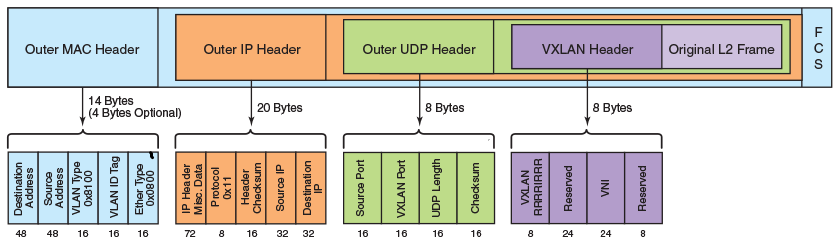
As you see, VXLAN is encapsulated into UDP, where destination port is fixed (4789) and points to VXLAN application. But source UDP port is variable, so per each new flow from one VTEP to another, source port will be different, what provides possibility for new output of hash function used to load share traffic across different links (within link aggregation group) or next-hops (for ECMP)

The only field within VXLAN header, which can be configured is VNI (virtual network identifier), which we can treat like VPN id (the same meaning as service label in MPLS, GRE key or even VLAN). It’s 24 bits long, so we have plenty of space to encode our services.

EVPN itself is explained in RFC7432, but you can also refer to my first article in order to get more info

What we are going to test?

We’ll configure Nokia (Alcatel-Lucent) SR OS routers SR1 and SR2 as leaf switches with VTEP functionality in order to interconnect two VMs (emulated by VRFs at Cisco IOS XR routers XR3 and XR4) residing in the same L2 domain. In GRT (global routing table) Cisco IOS XR routers will be acting as spine switches without any knowledge about EVPN/VXLAN overlay.

The success criteria for the lab is that we are able to ping from VM1 VM2 and see corresponding traffic in packet capture and appropriate info in control plane.

Software version

Comparing to the articles, I have written previously, now we are more bundled with “controller” part of the network, so the following setup is used:

See the one of previous articles to get details how to build the lab

Topology

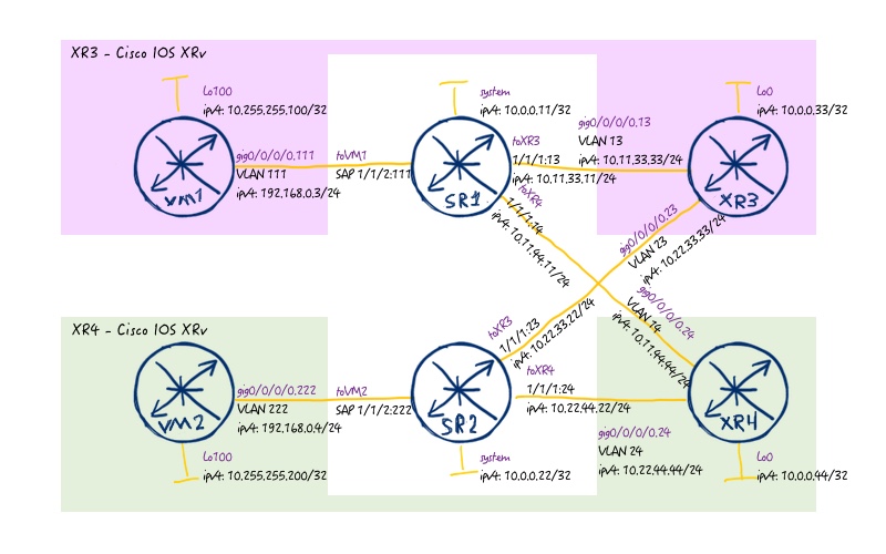
Our physical topology is stable, and if you tried the link above, you even know how to build it:

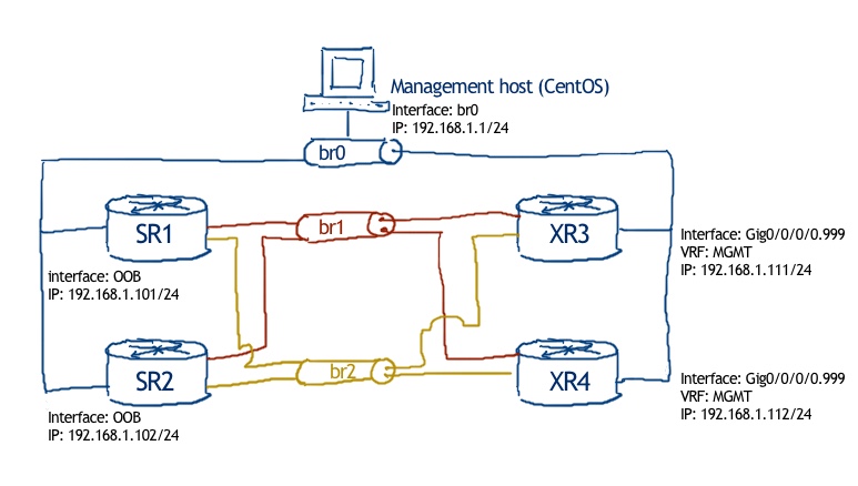
The logical topology is a bit extended from the default one:

If you checked the link above, you will get Ansible playbooks to deploy the core topology. What is missing, are the links to VMs and the VMs themselves. We’ll configure them later on in this lab. Those Ansible playbooks are also creates all necessary connectivity (Linux bridges) for our VNFs with virtual routers. If you don’t want to get all advances of automation, well, you can pick up these initial configuration files: 106_config_initial_SR1 106_config_initial_SR2 106_config_initial_XR3 106_config_initial_XR4 106_config_initial_linux

Configuration of underlay network infrastructure (IP fabric)

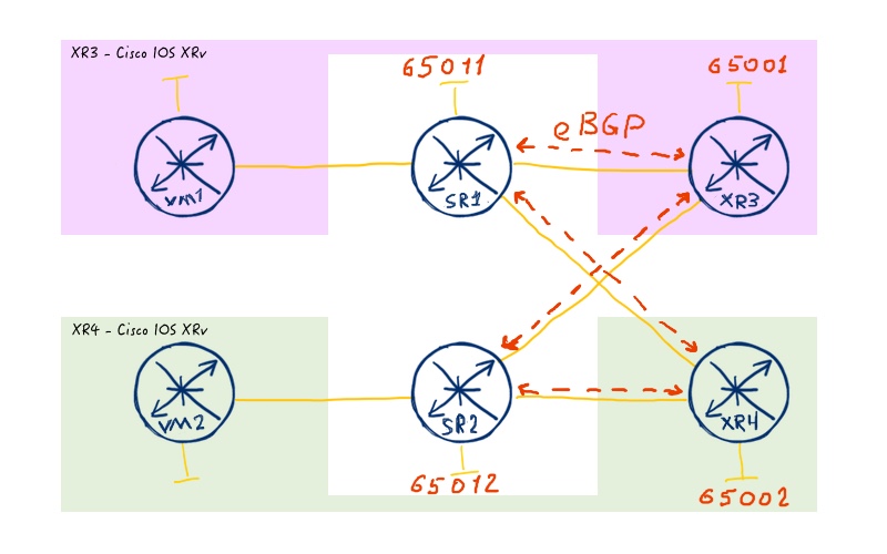
We start our lab activities with the configuration of the IPv4 fabric, using BGP. Such design is covered in RFC 79 38. IP addresses are configured using default lab setup (link), so we need to do the following steps:

We’ll consider this part as successfully done, when we can ping system interface of Nokia (Alcatel-Lucent) VSR SR2 from system interface of SR1.

BGP topology to deploy:

Here is the necessary configuration: .

Nokia (Alcatel-Lucent) SR OS Cisco IOS XR
SR1 XR3

A:SR1>edit-cfg# candidate view
=========================
configure
router
interface “toSR2”
shutdown
exit
autonomous-system 65011
ecmp 2
router-id 10.0.0.11
bgp
multipath 2
enable-peer-tracking
rapid-withdrawal
rapid-update l2-vpn mvpn-ipv4 mdt-safi mvpn-ipv6 evpn
next-hop-resolution
use-bgp-routes
exit
group “FABRIC”
family ipv4
authentication-key FABRIC
keepalive 5
hold-time 15
neighbor 10.11.33.33
peer-as 65001
exit
neighbor 10.11.44.44
peer-as 65002
exit
exit
no shutdown
exit
exit
exit
=========================

RP/0/0/CPU0:XR3(config)#show conf
!
interface GigabitEthernet0/0/0/0.34
shutdown
!
!
route-policy RP_PASS_ALL
pass
end-policy
!
router bgp 65001
timers bgp 5 15
bgp router-id 10.0.0.33
bgp log neighbor changes detail
address-family ipv4 unicast
!
neighbor 10.11.33.11
remote-as 65011
password clear FABRIC
address-family ipv4 unicast
send-community-ebgp
route-policy RP_PASS_ALL in
route-policy RP_PASS_ALL out
send-extended-community-ebgp
!
!
neighbor 10.22.33.22
remote-as 65012
password clear FABRIC
address-family ipv4 unicast
send-community-ebgp
route-policy RP_PASS_ALL in
route-policy RP_PASS_ALL out
send-extended-community-ebgp
!
!
!
end

SR2 XR4

A:SR2>edit-cfg# candidate view
=========================
configure
router
interface “toSR1”
shutdown
exit
autonomous-system 65012
ecmp 2
router-id 10.0.0.22
bgp
multipath 2
enable-peer-tracking
rapid-withdrawal
rapid-update l2-vpn mvpn-ipv4 mdt-safi mvpn-ipv6 evpn
next-hop-resolution
use-bgp-routes
exit
group “FABRIC”
family ipv4
authentication-key FABRIC
keepalive 5
hold-time 15
neighbor 10.22.33.33
peer-as 65001
exit
neighbor 10.22.44.44
peer-as 65002
exit
exit
no shutdown
exit
exit
exit
=========================

RP/0/0/CPU0:XR4(config)#show conf
!
interface GigabitEthernet0/0/0/0.34
shutdown
!
!
route-policy RP_PASS_ALL
pass
end-policy
!
router bgp 65002
timers bgp 5 15
bgp router-id 10.0.0.44
bgp log neighbor changes detail
address-family ipv4 unicast
!
neighbor 10.11.44.11
remote-as 65011
password clear FABRIC
address-family ipv4 unicast
send-community-ebgp
route-policy RP_PASS_ALL in
route-policy RP_PASS_ALL out
send-extended-community-ebgp
!
!
neighbor 10.22.44.22
remote-as 65012
password clear FABRIC
address-family ipv4 unicast
send-community-ebgp
route-policy RP_PASS_ALL in
route-policy RP_PASS_ALL out
send-extended-community-ebgp
!
!
!
end

For more details, refer to previous chapters: BGP and DC with MPLS

I hope that most of the configuration is familiar to you, if not – see the tip above. As a general consideration, I’ve reduced timers, because BFD doesn’t work on Cisco IOS XRv router. In real environment you will use BFD to track neighbour failure. We also enabled peer tracking at Nokia (Alcatel-Lucent) SR OS routes, which will speedup convergence later, when we configure multihop eBGP session for EVPN overlay. Next-hop resolution over BGP routes is necessary to make EVPN overlay as well, because next-hop for all EVPN routes will be system interfaces of another VSR learned through BGP IPv4 unicast (AFI/SAFI 1/1). Brief check that BGP sessions are up and running

RP/0/0/CPU0:XR3#show bgp ipv4 unicast summary
Neighbor        Spk    AS MsgRcvd MsgSent   TblVer InQ OutQ  Up/Down  St/PfxRcd
10.11.33.11       0 65011     176     179        2   0    0 00:14:48          0
10.22.33.22       0 65012     176     179        2   0    0 00:14:48          0
!
!
RP/0/0/CPU0:XR4#show bgp ipv4 uni summary
Neighbor        Spk    AS MsgRcvd MsgSent   TblVer InQ OutQ  Up/Down  St/PfxRcd
10.11.44.11       0 65011     144     148        2   0    0 00:12:03          0
10.22.44.22       0 65012     144     147        2   0    0 00:12:04          0

The final part of the configuration is to announce system interfaces. I put it separately, because the output above is already very long:

SR1 SR2

A:SR1>edit-cfg# candidate view
=========================
configure
router
policy-options
begin
prefix-list “PL_SYSTEM_IPV4”
prefix 10.0.0.11/32 exact
exit
policy-statement “RP_BGP_IPV4_UNICAST”
entry 10
from
protocol direct
prefix-list “PL_SYSTEM_IPV4”
exit
action accept
exit
exit
default-action drop
exit
exit
commit
exit
bgp
group “FABRIC”
export “RP_BGP_IPV4_UNICAST”
exit
exit
exit
exit
=========================

A:SR2>edit-cfg# candidate view
=========================
configure
router
policy-options
begin
prefix-list “PL_SYSTEM_IPV4”
prefix 10.0.0.22/32 exact
exit
policy-statement “RP_BGP_IPV4_UNICAST”
entry 10
from
protocol direct
prefix-list “PL_SYSTEM_IPV4”
exit
action accept
exit
exit
default-action drop
exit
exit
commit
exit
bgp
group “FABRIC”
export “RP_BGP_IPV4_UNICAST”
exit
exit
exit
exit
=========================

The configuration is absolutely identical, the only minor difference is the IPv4 addresses, which must be equal to local system interfaces.

After the configuration is applied, theses IP addresses are prorogated:

A:SR1# show router route-table
=================================================================================
Route Table (Router: Base)
=================================================================================
Dest Prefix[Flags]                            Type    Proto    Age        Pref
Next Hop[Interface Name]                                  Metric
=================================================================================
10.0.0.11/32                                  Local   Local    01h05m04s  0
system                                                    0
10.0.0.22/32                                  Remote  BGP      00h03m24s  170
10.11.33.33                                               0
10.0.0.22/32                                  Remote  BGP      00h03m24s  170
10.11.44.44                                               0
10.11.33.0/24                                 Local   Local    01h04m57s  0
toXR3                                                     0
10.11.44.0/24                                 Local   Local    01h04m53s  0
toXR4                                                     0
=================================================================================
No. of Routes: 5
Flags: n = Number of times nexthop is repeated
.      B = BGP backup route available
.      L = LFA nexthop available
.      S = Sticky ECMP requested
=================================================================================
!
!
A:SR2# show router route-table
=================================================================================
Route Table (Router: Base)
=================================================================================
Dest Prefix[Flags]                            Type    Proto    Age        Pref
Next Hop[Interface Name]                                  Metric
=================================================================================
10.0.0.11/32                                  Remote  BGP      00h06m12s  170
10.22.33.33                                               0
10.0.0.11/32                                  Remote  BGP      00h06m12s  170
10.22.44.44                                               0
10.0.0.22/32                                  Local   Local    00h56m32s  0
system                                                    0
10.22.33.0/24                                 Local   Local    00h56m28s  0
toXR3                                                     0
10.22.44.0/24                                 Local   Local    00h56m25s  0
toXR4                                                     0
=================================================================================
No. of Routes: 5
Flags: n = Number of times nexthop is repeated
.      B = BGP backup route available
.      L = LFA nexthop available
.      S = Sticky ECMP requested
=================================================================================

And routers can establish connectivity to each other:

A:SR1# ping 10.0.0.22 source 10.0.0.11 count 1
PING 10.0.0.22 56 data bytes
64 bytes from 10.0.0.22: icmp_seq=1 ttl=63 time=3.91ms.
—- 10.0.0.22 PING Statistics —-
1 packet transmitted, 1 packet received, 0.00% packet loss
round-trip min = 3.91ms, avg = 3.91ms, max = 3.91ms, stddev = 0.000ms

Our underlay fabric is ready and fully functional. So we can move to overlay configuration.

Configuration of overlay network infrastructure (EVPN + VXLAN)

Now, when IP fabric works, we need to perform some actions to get our L2 VPN working:

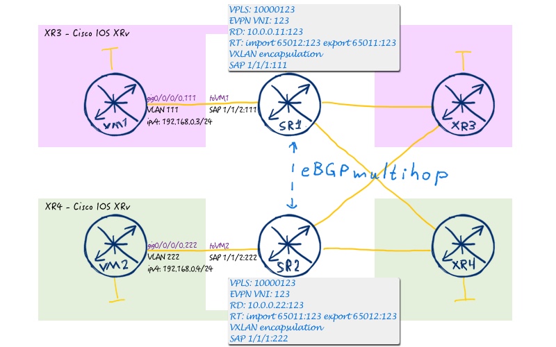
In total our service topology looks as follows:

#1. Configuration of EVPN AFI/SAFI in BGP

We start with the first point, as it’s quite simple and involve only Nokia (Alcatel-Lucent) SR OS routers:

SR1 SR2

A:SR1>edit-cfg# candidate view
=========================
configure
router
bgp
group “OVERLAY”
family evpn
authentication-key OVERLAY
multihop 10
local-address 10.0.0.11
neighbor 10.0.0.22
peer-as 65012
exit
exit
exit
exit
exit
=========================

A:SR2>edit-cfg# candidate view
=========================
configure
router
bgp
group “OVERLAY”
family evpn
authentication-key OVERLAY
multihop 10
local-address 10.0.0.22
neighbor 10.0.0.11
peer-as 65011
exit
exit
exit
exit
exit
=========================

The same construct we have used before upon configuration of Data Centre with BGP-LU/MPLS in data plane (link). Pay attention to multihop option, otherwise the peering won’t be established.

If everything is configured successfully, the BGP peering in EVPN address family goes up:

A:SR1# show router bgp summary
===============================================================================
BGP Router ID:10.0.0.11        AS:65011       Local AS:65011
===============================================================================
BGP Summary
===============================================================================
Legend : D – Dynamic Neighbor
===============================================================================
Neighbor
Description
.                  AS PktRcvd InQ  Up/Down State|Rcv/Act/Sent   (Addr Family)
.                     PktSent OutQ
===============================================================================
10.0.0.22
.               65012       9    0 00h02m28s 0/0/0 (Evpn)
.                           6    0
10.11.33.33
.               65001     319    0 00h26m20s 2/1/1 (IPv4)
.                         314    0
10.11.44.44
.               65002     310    0 00h21m47s 2/1/1 (IPv4)
.                         304    0
===============================================================================

As don’t have any VNIs configured, we don’t send or receive any prefixes.

#2. Configuration of EVPN service instances

This point is related solely to configuration of Nokia (Alcatel-Lucent) VSRs, much the same as the previous one. The reason is simple: Cisco IOS XR works as spine switches in our data centre fabric and they don’t know about any VXLAN traffic:

SR1 SR2

A:SR1>edit-cfg# candidate view
=========================
configure
port 1/1/2
ethernet
mode access
encap-type dot1q
exit
no shutdown
exit
service
customer 2 create
description “EVPN customer”
exit
vpls 10000123 customer 2 create
vxlan vni 123 create
exit
bgp
route-distinguisher 10.0.0.11:123
route-target export target:65011:123 import target:65012:123
exit
bgp-evpn
vxlan
no shutdown
exit
mpls
shutdown
exit
exit
stp
shutdown
exit
sap 1/1/2:111 create
no shutdown
exit
no shutdown
exit
exit
exit
=========================

A:SR2>edit-cfg# candidate view
=========================
configure
port 1/1/2
ethernet
mode access
encap-type dot1q
exit
no shutdown
exit
service
customer 2 create
description “EVPN customer”
exit
vpls 10000123 customer 2 create
vxlan vni 123 create
exit
bgp
route-distinguisher 10.0.0.22:123
route-target export target:65012:123 import target:65011:123
exit
bgp-evpn
vxlan
no shutdown
exit
mpls
shutdown
exit
exit
stp
shutdown
exit
sap 1/1/2:222 create
no shutdown
exit
no shutdown
exit
exit
exit
=========================

Once we have configured EVPN in EVPN-PBB fashion with MPLS encapsulation (link), so you can read some details there. In general, we have BGP VPN’s business as usual (RD/RT) and some new parameters (VXLAN VNI and VXLAN in BGP-EVPN).

What I have learned, Nokia (Alcatel-Lucent) SR OS doesn’t send EVPN type 1 route (Ethernet auto-discovery) by default, at least with VXLAN encapsulation.

Starting from this point both our Nokia (Alcatel-Lucent) SR OS routers SR1 and SR2 starts sending EVPN type-3 route (inclusive multicast), which is used for BUM (broadcast, unknown unicast, multicast) traffic:

A:SR1# show router bgp routes evpn inclusive-mcast
===============================================================================
BGP Router ID:10.0.0.11        AS:65011       Local AS:6501111
===============================================================================
Legend –
Status codes : u – used, s – suppressed, h – history, d – decayed, * – valid
.              l – leaked, x – stale, > – best, b – backup, p – purge
Origin codes : i – IGP, e – EGP, ? – incomplete
===============================================================================
BGP EVPN Inclusive-Mcast Routes
===============================================================================
Flag  Route Dist.         OrigAddr
.     Tag                 NextHop
===============================================================================
u*>i  10.0.0.22:123       10.0.0.22
.     0                   10.0.0.22
===============================================================================
Routes : 1
===============================================================================

As you remember (link to BGP article), in Nokia (Alcatel-Lucent) SR OS we see only received routed (Adj-RIB-In).

We can also check the VTEPs, which we have within our VNI:

A:SR1# show service id 10000123 vxlan
===============================================================================
Vxlan Src Vtep IP: N/A
===============================================================================
VPLS VXLAN, Ingress VXLAN Network Id: 123
Creation Origin: manual
Assisted-Replication: none
RestProtSrcMacAct: none
===============================================================================
VPLS VXLAN service Network Specifics
===============================================================================
Ing Net QoS Policy : none                            Vxlan VNI Id     : 123
Ingress FP QGrp    : (none)                          Ing FP QGrp Inst : (none)
===============================================================================
Egress VTEP, VNI
===============================================================================
VTEP Address                            Egress VNI  Num. MACs   Mcast Oper  L2
.                                                                     State PBR
===============================================================================
10.0.0.22                               123         0           BUM   Up    No
===============================================================================
Number of Egress VTEP, VNI : 1
===============================================================================

#3. Configuration of VM (emulation)

As we mentioned, we’ll create VRFs at Cisco IOS XR routers XR3 and XR4, which will act as emulation of VMs in our data centre:

XR3 XR4

RP/0/0/CPU0:XR3(config)#show conf
!
vrf VM1
address-family ipv4 unicast
!
!
interface GigabitEthernet0/0/0/0.111
vrf VM1
ipv4 address 192.168.0.3 255.255.255.0
encapsulation dot1q 111
!
end

RP/0/0/CPU0:XR3(config)#show conf
!
vrf VM2
address-family ipv4 unicast
!
!
interface GigabitEthernet0/0/0/0.222
vrf VM2
ipv4 address 192.168.0.4 255.255.255.0
encapsulation dot1q 222
!
end

Moreover we also need to configure bridge in Linux to provide connectivity between new VMs and leaf switches (SR1, SR2):

Linux

sudo /sbin/vconfig add vnet2 111
sudo /sbin/vconfig add ens34 111
sudo ifconfig vnet2.111 up
sudo ifconfig ens34.111 up
sudo brctl addbr br111
sudo brctl addif br111 vnet2.111
sudo brctl addif br111 ens34.111
sudo ifconfig br111 up
!
sudo /sbin/vconfig add vnet5 222
sudo /sbin/vconfig add ens34 222
sudo ifconfig vnet5.222 up
sudo ifconfig ens34.222 up
sudo brctl addbr br222
sudo brctl addif br222 vnet5.222
sudo brctl addif br222 ens34.222
sudo ifconfig br222 up

Verification of EVPN with VXLAN

The good information is that Nokia (Alcatel-Lucent) VSR are fully functionall router with working data plane for all type of services, comparing to Cisco IOS XRv, which can perform only control-plane for L2 VPNs, as we discussed before. That’s why we are able to perform full verification including sending data. Let’s issue ping packets from VM1 to VM2:

RP/0/0/CPU0:XR3#ping vrf VM1 192.168.0.4
Type escape sequence to abort.
Sending 5, 100-byte ICMP Echos to 192.168.0.4, timeout is 2 seconds:
!!!!!
Success rate is 100 percent (5/5), round-trip min/avg/max = 1/7/9 ms

In parallel we make a traffic capture in Wireshark:

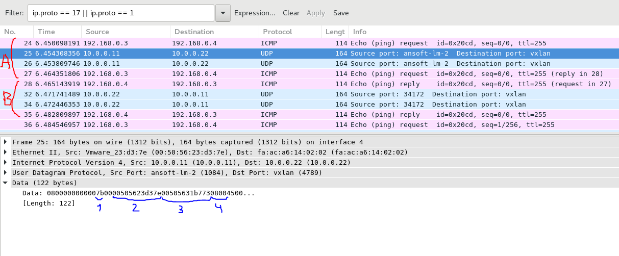
Some explanation to the PCAP above:

To provide more proof for explanation, we check the ARP table in emulated VM1 at Cisco IOS XR router XR3:

RP/0/0/CPU0:XR3#show arp vrf VM1
===============================================================================
0/0/CPU0
===============================================================================
Address       Age       Hardware Addr   State      Type Interface
192.168.0.3   –         0050.5631.b773  Interface  ARPA GigabitEthernet0/0/0/0.111
192.168.0.4   00:57:38  0050.5623.d37e  Dynamic    ARPA GigabitEthernet0/0/0/0.111

So, we got working EVPN solution with VXLAN encapsulation between Nokia (Alcatel-Lucent) SR OS routers SR1 and SR2. For Cisco IOS XR routers XR3 and XR4 this traffic is seen as ordinary IPv4 traffic, and they even don’t know that they forward EVPN in overlay. That’s what VXLAN about.

But for sure, information about VXLAN must present on VTEPs. First of all, let’s check BGP routing table:

A:SR1# show router bgp routes evpn mac
===============================================================================
BGP Router ID:10.0.0.11        AS:65011       Local AS:6501111
===============================================================================
Legend –
Status codes : u – used, s – suppressed, h – history, d – decayed, * – valid
.              l – leaked, x – stale, > – best, b – backup, p – purge
Origin codes : i – IGP, e – EGP, ? – incomplete
===============================================================================
BGP EVPN MAC Routes
===============================================================================
Flag  Route Dist.       MacAddr           ESI
.     Tag               Mac Mobility      Label1
.                       Ip Address
.                       NextHop
===============================================================================
u*>i 10.0.0.22:123      00:50:56:23:d3:7e ESI-0
.    0                  Seq:0             VNI 123
.                       N/A
.                       10.0.0.22
===============================================================================
Routes : 1
===============================================================================

We see MAC address of VM4 learned at VTEP SR1 in VNI 123. So control plane looks nice. What about data plane?

A :SR1# show service id 10000123 fdb detail
===============================================================================
Forwarding Database, Service 10000123
===============================================================================
ServId    MAC               Source-Identifier        Type  Last Change
.                                                    Age
===============================================================================
10000123  00:50:56:23:d3:7e vxlan:                   Evpn  02/10/18 20:50:08
.                           10.0.0.22:123
10000123 00:50:56:31:b7:73 sap:1/1/2:111             L/0   02/10/18 20:56:57
===============================================================================
No. of MAC Entries: 2
===============================================================================
Legend: L=Learned O=Oam P=Protected-MAC C=Conditional S=Static
===============================================================================

It looks good as well. So VTEP SR1 knows that it has local MAC of VM1 at SAP 1/1/2:111 and remote MAC from VM2 learned through VTEP 10.0.0.22 in VNI 123.

Final configuration files as they looks in CLI are here: 106_config_final_SR1 106_config_final_XR4 106_config_final_XR3 106_config_final_SR2 106_config_final_linux

Also you can use this Ansible playbooks, which deploys all necessary configuration through NETCONF with YANG data model: 106_lab.tar

The following sequence of Ansible playbooks is needs to be performed:

!— To create base topology
!
$ ansible-playbook default_lab_linux.yml
$ ansible-playbook default_lab_nokia.yml
$ ansible-playbook default_lab_cisco.yml
!
!— To perform activities from lab:
!
$ ansible-playbook netconf_nokia_enable.yml
$ ansible-playbook netconf_cisco_enable.yml
$ ansible-playbook lab_106_net_nokia.yml
$ ansible-playbook lab_106_net_linux.yml
$ ansible-playbook lab_106_net_cisco.yml

More info about lab building and NETCONF/YANG

Lessons learned

What I have missed in the initial lab deployment, is installation of wireshark. You can grab it by the following:

$ sudo yum install -y wireshark wireshark-gnome

As you see, we install two packages: one is for CLI and another is for GUI.

To launch it, you need to launch wireshark with root privileges, otherwise you will have empty list of the network interfaces (by default). Another solution would be to create appropriate groups and perform hell amount of other configuration, but I prefer the simple way:

$ sudo wireshark

Conclusion

As we briefly mentioned in the beginning, EVPN/VXLAN is currently de-facto standard for building data centre’s network. And all sizes of data centres, starting from just 4 switches deployment up to really big with hundreds of switches, will profit from its deployment. In general, EVPN is considered by many vendors as a full replacement of existing L2 VPN services and even potentially L3 VPN services (through usage of route type 5, we’ll write separate article about it). If you aren’t familiar with this technology, I strongly advise you to invest your time in learning it and doing this lab.Take and good bye!

P.S.

If you have further questions or you need help with your networks, I’m happy to assist you, just send me message. Also don’t forget to share the article on your social media, if you like it.

Support us


BR,

Anton Karneliuk

Exit mobile version