


Hello my friend,
with this article we’ll close our series of EVPN/VXLAN articles, we started some time ago with pure switching (L2) and distributed gateway (L3) for EVPN/VXLAN. In present article we’ll talk about so called L3 OUT functionality, where customer within tenant should speak dynamic routing with the leaf switch.
1 2 3 4 5 | No part of this blogpost could be reproduced, stored in a<br> retrieval system, or transmitted in any form or by any<br> means, electronic, mechanical or photocopying, recording,<br> or otherwise, for commercial purposes without the<br> prior permission of the author.<br> |
Disclaimer
Start with the L2 configuration and L3 configuration for EVPN/VXLAN to get full understanding of what is going on here.
Brief description
Related use case, where we need to make dynamic routing between customer VNF in tenant and our DC fabric, isn’t quite common. It isn’t standard web-based application or something similar. But it’s still valid. For example, distributed load balancer, which distributes customer sessions across lots of frontends, or distributed NAT/FW application, which pass the customer traffic between security zones. From example above we can distinguish two important capabilities of such flows:
- They are statefull. So traffic flow should pass only certain device in both directions.
- System, which traffic pass, is distributed. Probably, if you have big HW-load balancer, you might not need to have routing protocols, but of you used set of VNFs across different racks, you will need to know, which exactly VNF the traffic has pass in one direction in order to send it back through the same VNF
What we are going to test?
In order to show, how BGP peering is working between VM and Leaf, we’ll announce loopback from each VM to the cloud. The success criteria for the lab is possibility to reach any VM’s loopback from any another VM’s loopback.
Software version
The following infrastructure is used in my lab:
- CentOS 7 with python 2.7.
- Ansible 2.4.2
- Nokia (Alcatel-Lucent) SR OS 14.0.R4
- Cisco IOS XRv 6.1.2
See the previous article to get details how to build the lab
Topology
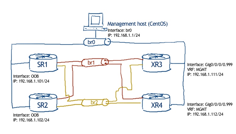
The physical topology is standard for our labs:

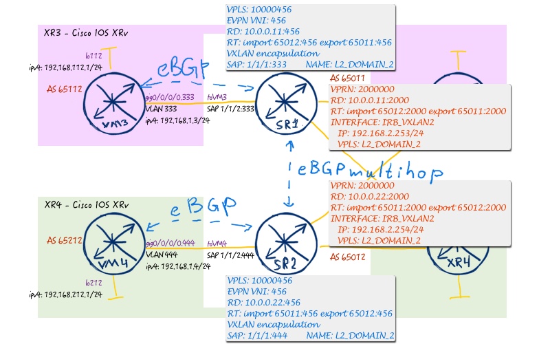
Logical topology is the same, as we have in previous lab. But as we are touching only service part, only respective servies will be shown. Service#1 looks like:


Service #2 has the following topology:
Initial configuration files in this lab are the finish one, from the previous one
Configuration eBGP PE-CE peering between Nokia (Alcatel-Lucent) SR OS and Cisco IOS XR
From the point of view of the activities, we need to do the following stuff:
- Enable propagation of EVPN type-5 routes
- Configure BGP and policies on Leaf within customer VPN
- Configure BGP and policies at VM side
Let’s view in details, what we configure per vendor
#1. Configuration of leaf switches // Nokia (Alcatel-Lucent) SR OS
Pay attention that only incremental configuration is shown here. The rest of the configuration you can find in Part 1 and Part 2
Here we go:
| SR1 | SR2 |
|
A:SR1>edit-cfg# candidate view |
A:SR2>edit-cfg# candidate view |
In the VPLS part we need to enable type 5 routes of EVPN. Though we did it previously, I have highlighted it here once more.
Then we configure BGP for PE-CE peering. In order to advertise routes, learned from EVPN, we need to allow them in the export policy. There are several ways, how we can achieve that. Here we take just the option to control export by allowing certain prefixes in prefix lists.
The third important point is changing of preference (administrative distance – AD – in Cisco words). The reason, why we need to do that, is that by default AD of BGP routes is 170 and 169 for BGP EVPN. So, routes are getting in kind of loop, that Leaf switches shows to another Leaf, as learned back routes have better priority. When we change AD so that locally learned BGP routes are more preferable, than the loop is broken and routing works properly.
Let’s review configuration of Cisco side now.
#2. Configuration of VMs // Cisco IOS XR
Here the configuration is quite trivial:
| Cisco IOS XR (XR3) | Cisco IOS XR (XR4) |
|
RP/0/0/CPU0:XR3(config-bgp-vrf-nbr-af)#show conf |
RP/0/0/CPU0:XR4(config-bgp-vrf-nbr-af)#show conf |
The only point that is worth mentioning is changes of local-as in order to simulate different customers.
See more details on BGP configuration in the corresponding article.
Verification
We start verification with routing tables. On SR1, which is Nokia (Alcatel-Lucent) SR OS based data centre leaf, we see the following picture:
1 2 3 4 5 6 7 8 9 10 11 12 13 14 15 16 17 18 19 20 21 22 23 24 25 26 27 28 29 30 | A:SR1# show router 20000000 route-table<br> ===============================================================================<br> Route Table (Service: 20000000)<br> ===============================================================================<br> Dest Prefix[Flags] Type Proto Age Pref<br> Next Hop[Interface Name] Metric<br> -------------------------------------------------------------------------------<br> 192.168.0.0/24 Local Local 01h41m57s 0<br> IRB_VXLAN1 0<br> 192.168.0.254/32 Remote BGP EVPN 01h41m57s 169<br> 192.168.1.254 0<br> 192.168.1.0/24 Local Local 01h41m57s 0<br> IRB_VXLAN2 0<br> 192.168.1.254/32 Remote BGP EVPN 01h41m57s 169<br> 192.168.0.254 0<br> 192.168.111.0/24 Remote BGP 00h37m52s 165<br> 192.168.0.3 0<br> 192.168.112.0/24 Remote BGP 00h38m03s 165<br> 192.168.1.3 0<br> 192.168.211.0/24 Remote BGP EVPN 00h48m23s 169<br> 192.168.1.254 0<br> 192.168.212.0/24 Remote BGP EVPN 00h48m23s 169<br> 192.168.0.254 0<br> -------------------------------------------------------------------------------<br> No. of Routes: 8<br> Flags: n = Number of times nexthop is repeated<br> B = BGP backup route available<br> L = LFA nexthop available<br> S = Sticky ECMP requested<br> =============================================================================== |
As we have changed the preference for routing table, you see the correct routing here. On connected VM, which is Cisco IOS XR router we see:
1 2 3 4 5 6 7 8 9 10 11 12 13 14 15 16 17 18 19 20 21 22 23 | RP/0/0/CPU0:XR3#show route vrf VM1<br> .<br> Codes: C - connected, S - static, R - RIP, B - BGP, (>) - Diversion path<br> D - EIGRP, EX - EIGRP external, O - OSPF, IA - OSPF inter area<br> N1 - OSPF NSSA external type 1, N2 - OSPF NSSA external type 2<br> E1 - OSPF external type 1, E2 - OSPF external type 2, E - EGP<br> i - ISIS, L1 - IS-IS level-1, L2 - IS-IS level-2<br> ia - IS-IS inter area, su - IS-IS summary null, * - candidate default<br> U - per-user static route, o - ODR, L - local, G - DAGR, l - LISP<br> A - access/subscriber, a - Application route<br> M - mobile route, r - RPL, (!) - FRR Backup path<br> .<br> Gateway of last resort is 192.168.0.253 to network 0.0.0.0<br> .<br> S* 0.0.0.0/0 [1/0] via 192.168.0.253, 01:43:03<br> C 192.168.0.0/24 is directly connected, 01:46:50, GigabitEthernet0/0/0/0.111<br> L 192.168.0.3/32 is directly connected, 01:46:50, GigabitEthernet0/0/0/0.111<br> B 192.168.1.0/24 [20/0] via 192.168.0.253, 00:32:18<br> C 192.168.111.0/24 is directly connected, 01:01:53, Loopback111<br> L 192.168.111.1/32 is directly connected, 01:01:53, Loopback111<br> B 192.168.112.0/24 [20/0] via 192.168.0.253, 00:38:54<br> B 192.168.211.0/24 [20/0] via 192.168.0.253, 00:32:18<br> B 192.168.212.0/24 [20/0] via 192.168.0.253, 00:32:18<br> |
Of the particular interest would be the BGP EVPN RIB on Nokia (Alcatel-Lucent) SR OS devices:
1 2 3 4 5 6 7 8 9 10 11 12 13 14 15 16 17 18 19 20 21 22 23 24 25 26 27 28 29 30 31 32 33 34 35 36 37 38 39 40 41 42 43 44 45 46 47 48 49 50 51 52 53 54 55 56 57 58 59 60 61 62 63 64 65 66 67 68 | A:SR1# show router bgp routes evpn ip-prefix<br> ===============================================================================<br> BGP Router ID:10.0.0.11 AS:65011 Local AS:65011<br> ===============================================================================<br> Legend -<br> Status codes : u - used, s - suppressed, h - history, d - decayed, * - valid<br> . l - leaked, x - stale, > - best, b - backup, p - purge<br> Origin codes : i - IGP, e - EGP, ? - incomplete<br> ===============================================================================<br> BGP EVPN IP-Prefix Routes<br> ===============================================================================<br> Flag Route Dist. Prefix<br> . Tag Gw Address<br> . NextHop<br> . Label<br> -------------------------------------------------------------------------------<br> u*>i 10.0.0.22:123 192.168.0.253/32<br> . 0 192.168.0.254<br> . 10.0.0.22<br> . VNI 123<br> .<br> u*>i 10.0.0.22:123 192.168.1.254/32<br> . 0 192.168.0.254<br> . 10.0.0.22<br> . VNI 123<br> .<br> u*>i 10.0.0.22:123 192.168.1.0/24<br> . 0 192.168.0.254<br> . 10.0.0.22<br> . VNI 123<br> .<br> u*>i 10.0.0.22:123 192.168.111.0/24<br> . 0 192.168.0.254<br> . 10.0.0.22<br> . VNI 123<br> .<br> u*>i 10.0.0.22:123 192.168.212.0/24<br> . 0 192.168.0.254<br> . 10.0.0.22<br> . VNI 123<br> .<br> u*>i 10.0.0.22:456 192.168.0.254/32<br> . 0 192.168.1.254<br> . 10.0.0.22<br> . VNI 456<br> .<br> u*>i 10.0.0.22:456 192.168.1.253/32<br> . 0 192.168.1.254<br> . 10.0.0.22<br> . VNI 456<br> .<br> u*>i 10.0.0.22:456 192.168.0.0/24<br> . 0 192.168.1.254<br> . 10.0.0.22<br> . VNI 456<br> .<br> u*>i 10.0.0.22:456 192.168.112.0/24<br> . 0 192.168.1.254<br> . 10.0.0.22<br> . VNI 456<br> .<br> u*>i 10.0.0.22:456 192.168.211.0/24<br> . 0 192.168.1.254<br> . 10.0.0.22<br> . VNI 456<br> -------------------------------------------------------------------------------<br> Routes : 10<br> ===============================================================================<br> |
You might see in this table, that best IP route within EVPN still points to another leaf, though routing table is correct. In this table you see all the related routes.
At Cisco IOS XR side, which is VM2, there is no something special:
1 2 3 4 5 6 7 8 9 10 11 12 13 14 15 16 17 18 19 20 21 22 23 24 25 26 27 28 29 30 31 | RP/0/0/CPU0:XR3#show bgp vpnv4 unicast<br> Sun Mar 18 19:47:52.254 UTC<br> BGP router identifier 10.0.0.33, local AS number 65001<br> BGP generic scan interval 60 secs<br> Non-stop routing is enabled<br> BGP table state: Active<br> Table ID: 0x0 RD version: 0<br> BGP main routing table version 21<br> BGP NSR Initial initsync version 7 (Reached)<br> BGP NSR/ISSU Sync-Group versions 0/0<br> BGP scan interval 60 secs<br> .<br> Status codes: s suppressed, d damped, h history, * valid, > best<br> i - internal, r RIB-failure, S stale, N Nexthop-discard<br> Origin codes: i - IGP, e - EGP, ? - incomplete<br> Network Next Hop Metric LocPrf Weight Path<br> Route Distinguisher: 65001:65111 (default for vrf VM1)<br> *> 192.168.0.0/24 192.168.0.253 0 65011 i<br> *> 192.168.1.0/24 192.168.0.253 0 65011 i<br> *> 192.168.111.0/24 0.0.0.0 0 32768 i<br> *> 192.168.112.0/24 192.168.0.253 0 65011 65112 i<br> *> 192.168.211.0/24 192.168.0.253 0 0 65011 i<br> *> 192.168.212.0/24 192.168.0.253 0 0 65011 i<br> Route Distinguisher: 65001:65112 (default for vrf VM3)<br> *> 192.168.0.0/24 192.168.1.253 0 65011 i<br> *> 192.168.1.0/24 192.168.1.253 0 65011 i<br> *> 192.168.111.0/24 192.168.1.253 0 65011 65111 i<br> *> 192.168.112.0/24 0.0.0.0 0 32768 i<br> *> 192.168.211.0/24 192.168.1.253 0 0 65011 i<br> *> 192.168.212.0/24 192.168.1.253 0 0 65011 i<br> Processed 12 prefixes, 12 paths |
The final part of our verifications, as we have discussed so far, is ping between loopbacks.
So.. Ping time!
1 2 3 4 5 6 7 8 9 10 11 12 13 14 15 16 17 18 19 20 21 22 23 24 | RP/0/0/CPU0:XR4#ping vrf VM2 192.168.111.1 so lo211<br> Sun Mar 18 19:49:06.779 UTC<br> Type escape sequence to abort.<br> Sending 5, 100-byte ICMP Echos to 192.168.111.1, timeout is 2 seconds:<br> !!!!!<br> Success rate is 100 percent (5/5), round-trip min/avg/max = 1/7/9 ms<br> RP/0/0/CPU0:XR4#ping vrf VM2 192.168.112.1 so lo211<br> Sun Mar 18 19:49:10.449 UTC<br> Type escape sequence to abort.<br> Sending 5, 100-byte ICMP Echos to 192.168.112.1, timeout is 2 seconds:<br> !!!!!<br> Success rate is 100 percent (5/5), round-trip min/avg/max = 1/7/9 ms<br> RP/0/0/CPU0:XR4#ping vrf VM2 192.168.212.1 so lo211<br> Sun Mar 18 19:49:13.918 UTC<br> Type escape sequence to abort.<br> Sending 5, 100-byte ICMP Echos to 192.168.212.1, timeout is 2 seconds:<br> !!!!!<br> Success rate is 100 percent (5/5), round-trip min/avg/max = 1/4/9 ms<br> RP/0/0/CPU0:XR4#ping vrf VM2 192.168.211.1 so lo211<br> Sun Mar 18 19:49:17.048 UTC<br> Type escape sequence to abort.<br> Sending 5, 100-byte ICMP Echos to 192.168.211.1, timeout is 2 seconds:<br> !!!!!<br> Success rate is 100 percent (5/5), round-trip min/avg/max = 1/1/1 ms<br> |
Final configuration files: 114_config_final_linux 114_config_final_SR1 114_config_final_SR2 114_config_final_XR3 114_config_final_XR4
Ansible playbook to reach that state from initial configurations:
Lessons learned
What goes around, comes around. I mean that toolset, regardless of technologies is always the same. For example, preference or administrative distance. This tool is very old, but we suddenly it comes back into game, when we start speaking about EVPN as replacement for traditional IP VPNs. So, don’t forget old school tools, even if you deal with the mega modern technologies
Conclusion
As you have seen over a couple of last articles, EVPN can do all things, like L2 VPNs, L3 VPNs and even incorporate PE-CE routing. By the end of the day, it means that this particular address-family can replace all other BGP signalling flavours. Especially, when we take into consideration, that it can works both with MPLS and VXLAN data plane, EVPN is really powerful. Take care and good bye!
P.S.
If you have further questions or you need help with your networks, I’m happy to assist you, just send me message. Also don’t forget to share the article on your social media, if you like it.
Support us
BR,
Anton Karneliuk