


Hello my friend,
Two years ago we’ve discussed how to configure Segment Routing between Nokia (Alcatel-Lucent) SR OS and Cisco IOS XR. Both of these vendors are well-known in Service Provider industry as they are delivering networks in this filed for a long time. But the world isn’t stable and nobody knows what will happen tomorrow. And traditional data centre vendors start looking to SP WAN.
2
3
4
5
retrieval system, or transmitted in any form or by any
means, electronic, mechanical or photocopying, recording,
or otherwise, for commercial purposes without the
prior permission of the author.
Brief description
I won’t explain the details of Segment-Routing or IP VPN as it was done previously. Please, refer to those articles. In this article, we’ll take a look on multivendor topology with Segment Routing as MPLS data plane and IP VPN as service running in top. Both these features are quite new to Arista, and for example IP VPN was released just recently, though EVPN was there for quite a long time.
In general, we could say that Segment Routing with IP VPN (or any kind of L2 service on top) is de facto standard for modern service provider networks in the same manner as EVPN/VXLAN for modern data centres.
What are we going to test?
We will test the communication of the customers within IP VPN connected to PE network functions running on Arista EOS, Cisco IOS XR and Nokia (Alcatel-Lucent) SR OS. The MPLS data will be done using Segment Routing.
Software version
The following software components are used in this lab:
- CentOS 7.5.1804 with python 2.7.5
- Ansible 2.7.0
- Nokia SR OS 16.0.R4 [guest VNF]
- Cisco IOS XR 6.1.2 [guest VNF]
- Arista EOS 4.21.1.F [guest VNF]
See the previous article to get details how to build the lab
Topology
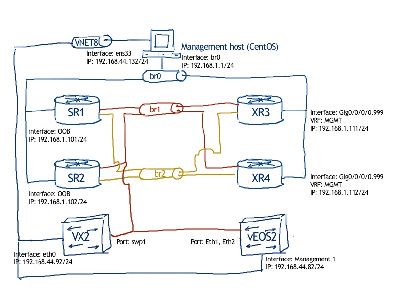
The physical topology is exactly the same as we have used for all our labs, even the data centres:

The logical topology is the same, as we had previously in original Segment Routing lab, where we just replace Nokia SR OS based router SR2 to Arista EOS based router EOS1:
2
3
4
5
6
7
8
9
10
11
12
13
14
15
16
17
18
19
20
| |
| 10.11.22.0/24 |
| +--------------------------------------------------------------------------------------------+ |
| | 1/1/c1/1:0 Eth1 | |
| | .11 .22 | |
| +-------+--------+ 10.11.33.0/24 +----------------+ 10.22.33.0/24 +--------+-------+ |
| | SR1 (AS:65000) +----------------------------+ XR3 (AS:65000) +----------------------------+ EOS2(AS:65000) | |
| +-------+--------+ 1/1/c1/1:13 g0/0/0/0.13 +--------+-------+ g0/0/0/1 Eth2 +--------+-------+ |
| | .11 .33 | .33 .22 | |
| | | | |
| | system: 10.0.0.11/32 | loopback0: 10.0.0.33/32 | loopback0: 10.0.0.22/32 |
| |
| <-----------BGP:VPNV4_UNI/VPNV6_UNI------------x-----------BGP:VPNV4_UNI/VPNV6_UNI-----------> |
| <-----------------------------------BGP:VPNV4_UNI/VPNV6_UNI----------------------------------> |
| |
| |
| ISIS 0 (CORE) / level-2 / Segment Routing |
| |
+----------------------------------------------------------------------------------------------------------------------------------+
All the interconnect links as well as system interface or loopback 0 will be part of ISIS process called CORE on Cisco XR3 and Arista EOS2 and having ID 0 at Nokia SR1. The BGP process will be configure in a full-mesh manner between loopbacks 0 and system interface at PE routers for VPNv4/VPNv6 unicast address families (AFI/SAFI: 1/128, 2/128).
Initial configuration you can find on my GitHub page.
Configuration of underlay infrastructure for Arista, Cisco, Nokia: MPLS data plane (ISIS-SR)
Let’s get started. First of all, we need to configure IGP to provide connectivity between all the loopbacks 0 and system interface of the routers so that we can establish full-mesh iBGP later on. As we need to establish BGP only loopbacks, we announce only passive interfaces and we make loopbacks 0 and system interface as passive interface in ISIS. Also we configure Segment Routing now to establish working MPLS data plane for traffic forwarding. The good point is that the configuration is fairly simple as you can see below.
The first in a row is the ISIS and Segment Routing configuration for Arista EOS based network function EOS2 running EOS 4.21.1.1F:
2
3
4
5
6
7
8
9
10
11
12
13
14
15
16
17
18
19
20
21
22
23
24
25
26
27
28
29
30
31
32
33
34
! Command: show running-config
! device: EOS2 (vEOS, EOS-4.21.1.1F)
!
service routing protocols model multi-agent
!
mpls ip
!
router isis CORE
net 49.0000.0100.0000.0022.00
is-type level-2
log-adjacency-changes
advertise passive-only
!
address-family ipv4 unicast
!
segment-routing mpls
router-id 10.0.0.22
no shutdown
prefix-segment 10.0.0.22/32 index 22
!
interface Loopback0
isis enable CORE
isis passive
!
interface Ethernet1
isis enable CORE
isis network point-to-point
!
interface Ethernet2
isis enable CORE
isis network point-to-point
!
end
For some of, you have the experience with different Cisco products, the configuration is pretty simple and well-known. We’ve discussed this earlier in data-center articles. The key point is to enable ISIS on all the respective interfaces and to announce loopback with associated prefix SID for Segment Routing. Also, pay attention that segment routing requires additional router-id within the process.
You can’t change metric-style, it is wide by default, so make sure other routers have the same metric style.
The second station in the configuration journey is the ISIS and Segment Routing configuration for Nokia SR OS based network function SR1 running SR OS 16.0.R4 in model-driven mode:
2
3
4
5
6
7
8
9
10
11
12
13
14
15
16
17
18
19
20
21
22
23
24
25
26
27
28
29
30
31
32
33
34
35
36
37
38
39
40
41
42
43
44
45
A:admin@SR1# compare
configure {
router "Base" {
+ router-id 10.0.0.11
+ mpls-labels {
+ sr-labels {
+ start 500000
+ end 524287
+ }
+ }
+ isis 0 {
+ admin-state enable
+ advertise-passive-only true
+ advertise-router-capability as
+ level-capability 2
+ area-address [49.0000]
+ segment-routing {
+ admin-state enable
+ tunnel-table-pref 8
+ prefix-sid-range {
+ global
+ }
+ }
+ interface "system" {
+ admin-state enable
+ passive true
+ ipv4-node-sid {
+ index 11
+ }
+ }
+ interface "toEOS2" {
+ admin-state enable
+ interface-type point-to-point
+ }
+ interface "toXR3" {
+ admin-state enable
+ interface-type point-to-point
+ }
+ level 2 {
+ wide-metrics-only true
+ }
+ }
}
}
In greater details the configuration of ISIS at Nokia SR OS and Segment Routing in Nokia SR OS was explained earlier. What is new here is the 16.0.R4 version, so you can see that some commands are new or have different format.
Don’t forget to define MPLS label range for Segment Routing
The last point in creation of the ISIS-SR underlay is the configuration of ISIS and Segment Routing for Cisco IOS XR based network function XR3 (the 3rd PE) running XR 6.1.2:
2
3
4
5
6
7
8
9
10
11
12
13
14
15
16
17
18
19
20
21
22
23
24
25
26
27
28
29
30
31
32
33
Sun Nov 25 10:56:32.538 UTC
Building configuration...
!! IOS XR Configuration 6.1.2
!! Last configuration change at Sun Nov 25 10:56:15 2018 by cisco
!
router isis CORE
is-type level-2-only
net 49.0000.0100.0000.0033.00
log adjacency changes
address-family ipv4 unicast
metric-style wide
advertise passive-only
segment-routing mpls sr-prefer
!
interface Loopback0
passive
address-family ipv4 unicast
prefix-sid index 33
!
!
interface GigabitEthernet0/0/0/0.13
point-to-point
address-family ipv4 unicast
!
!
interface GigabitEthernet0/0/0/1
point-to-point
address-family ipv4 unicast
!
!
!
end
Again, both ISIS and SR were explained in greater details earlier, so here we just do the same set of commands we’ve done already twice today, now in Cisco IOS XR language.
After the configuration of ISIS and Segment Routing is done, the next logical step is to make some verifications. The first one is to check the ISIS adjacency to see if the routers are connected to each other. The following example shows such verification of ISIS neighbors in Arista EOS:
2
3
4
5
6
7
8
9
10
11
12
13
14
15
16
17
18
19
20
21
22
23
24
25
26
27
28
Instance VRF System Id Type Interface SNPA State Hold time Circuit Id
CORE default SR1 L2 Ethernet1 P2P UP 19 00
Area Address(es): 49.0000
SNPA: P2P
Advertised Hold Time: 27
State Changed: 00:17:13 ago
IPv4 Interface Address: 10.11.22.11
IPv6 Interface Address: none
Interface name: Ethernet1.12
Graceful Restart: Not Supported
Segment Routing Enabled
Router ID: 10.0.0.11
SRGB Base: 500000 Range: 24288
Adjacency Label IPv4: 100000
CORE default XR3 L2 Ethernet2 P2P UP 25 00
Area Address(es): 49.0000
SNPA: P2P
Advertised Hold Time: 30
State Changed: 01:14:19 ago
IPv4 Interface Address: 10.22.33.33
IPv6 Interface Address: none
Interface name: Ethernet2
Graceful Restart: Supported
Segment Routing Enabled
Router ID: 10.0.0.33
SRGB Base: 16000 Range: 8000
Adjacency Label IPv4: 116384
You can (and probably should) do the same check on 2 other vendors. Below you have the commands to get the same information for Nokia (Alcatel-Lucent) SR OS and Cisco IOS XR:
2
3
RP/0/0/CPU0:XR3#show isis neighbors detail
The output is truncated in order to reduce the length of the article. It’s just important to understand how the same information can be viewed on different platforms
The first verification step is successful, so we move further. After the ISIS adjacency is established, you should check, what information is distributed via ISIS and contained in ISIS LSDB (link-state data base. The following example shows, how to review the content of ISIS database in Cisco IOS XR:
2
3
4
5
6
7
8
9
10
11
12
13
14
15
16
17
18
19
20
21
22
23
24
25
26
27
28
29
30
31
32
33
34
35
36
37
38
39
40
41
42
43
44
45
46
47
48
49
50
51
52
53
Sun Nov 25 10:57:22.284 UTC
IS-IS CORE (Level-2) Link State Database
LSPID LSP Seq Num LSP Checksum LSP Holdtime ATT/P/OL
EOS2.00-00 0x0000000c 0x6d54 1142 0/0/0
Area Address: 49.0000
NLPID: 0xcc
Metric: 10 IS-Extended XR3.00
ADJ-SID: F:0 B:0 V:1 L:1 S:0 weight:0 Adjacency-sid:116384
Neighbor IP Address: 10.22.33.33
Interface IP Address: 10.22.33.22
Router Cap: 10.0.0.22, D:0, S:0
Segment Routing: I:1 V:0, SRGB Base: 900000 Range: 16
Hostname: EOS2
IP Address: 10.22.33.22
IP Address: 10.11.22.22
IP Address: 10.0.0.22
Metric: 10 IP-Extended 10.0.0.22/32
Prefix-SID Index: 22, Algorithm:0, R:0 N:0 P:0 E:0 V:0 L:0
SR1.00-00 0x0000000c 0x91bc 746 0/0/0
Area Address: 49.0000
NLPID: 0xcc
Hostname: SR1
Router ID: 10.0.0.11
Router Cap: 10.0.0.11, D:0, S:0
TE PCE Discovery (Old):
PCE sub TLV 232: Length 2
Segment Routing: I:1 V:1, SRGB Base: 500000 Range: 24288
SubTLV 19Length: 1
IP Address: 10.0.0.11
IP Address: 10.11.22.11
IP Address: 10.11.33.11
Metric: 10 IS-Extended XR3.00
Interface IP Address: 10.11.33.11
Neighbor IP Address: 10.11.33.33
ADJ-SID: F:0 B:0 V:1 L:1 S:0 weight:0 Adjacency-sid:499998
Metric: 0 IP-Extended 10.0.0.11/32
Prefix-SID Index: 11, Algorithm:0, R:0 N:1 P:1 E:0 V:0 L:0
XR3.00-00 * 0x00000004 0x1307 1145 0/0/0
Area Address: 49.0000
NLPID: 0xcc
Hostname: XR3
IP Address: 10.0.0.33
Router Cap: 10.0.0.33, D:0, S:0
Segment Routing: I:1 V:0, SRGB Base: 16000 Range: 8000
Metric: 10 IS-Extended EOS2.00
Interface IP Address: 10.22.33.33
Neighbor IP Address: 10.22.33.22
ADJ-SID: F:0 B:1 V:1 L:1 S:0 weight:0 Adjacency-sid:24000
ADJ-SID: F:0 B:0 V:1 L:1 S:0 weight:0 Adjacency-sid:24001
Metric: 0 IP-Extended 10.0.0.33/32
Prefix-SID Index: 33, Algorithm:0, R:0 N:1 P:0 E:0 V:0 L:0
Total Level-2 LSP count: 3 Local Level-2 LSP count: 1
The most important information for us (besides IP addresses of loopbacks/system interface) is range of Segment Routing labels expressed as “SRGB Base” and “SRGB Range” and Prefix-SID index for loopback/system prefixes.
The same information is collected at Nokia (Alcatel-Lucent) SR OS and Arista EOS network functions using the following commands:
2
3
EOS2#show isis database detail
The last point in this verification process is to check, what we have in LFIB (Label forwarding information base – MPLS data plane) as these labels associated with IP addresses of loopbacks/system interfaces will be used for actual data forwarding. The following examples show such check in Nokia SR OS:
2
3
4
5
6
7
8
9
10
11
12
13
14
15
16
17
18
19
20
21
22
23
24
25
26
27
28
29
30
31
32
33
34
35
36
37
38
39
40
41
42
43
44
45
46
47
===============================================================================
Tunnel Table (Router: Base)
===============================================================================
Destination : 10.0.0.22/32
NextHop : 10.11.22.22
Tunnel Flags : entropy-label-capable
Age : 00h38m11s
CBF Classes : (Not Specified)
Owner : isis (0) Encap : MPLS
Tunnel ID : 524290 Preference : 8
Tunnel Label : 3 Tunnel Metric : 20
Tunnel MTU : 9190 Max Label Stack : 1
-------------------------------------------------------------------------------
Destination : 10.0.0.33/32
NextHop : 10.11.33.33
Tunnel Flags : entropy-label-capable
Age : 00h37m23s
CBF Classes : (Not Specified)
Owner : isis (0) Encap : MPLS
Tunnel ID : 524292 Preference : 8
Tunnel Label : 3 Tunnel Metric : 10
Tunnel MTU : 9190 Max Label Stack : 1
-------------------------------------------------------------------------------
Destination : 10.11.22.22/32
NextHop : 10.11.22.22
Tunnel Flags : is-adjacency-tunnel
Age : 00h40m49s
CBF Classes : (Not Specified)
Owner : isis (0) Encap : MPLS
Tunnel ID : 524289 Preference : 8
Tunnel Label : 3 Tunnel Metric : 0
Tunnel MTU : 9190 Max Label Stack : 1
-------------------------------------------------------------------------------
Destination : 10.11.33.33/32
NextHop : 10.11.33.33
Tunnel Flags : is-adjacency-tunnel
Age : 00h37m29s
CBF Classes : (Not Specified)
Owner : isis (0) Encap : MPLS
Tunnel ID : 524291 Preference : 8
Tunnel Label : 3 Tunnel Metric : 0
Tunnel MTU : 9190 Max Label Stack : 1
-------------------------------------------------------------------------------
Number of tunnel-table entries : 4
Number of tunnel-table entries with LFA : 0
===============================================================================
It’s crucial to have the first two routes as later on system/loopback interfaces will be used as BGP next-hops, hence we need to have MPLS labels for them You see that the label value is “3” both for Arista EOS and Cisco IOS XR based routers, as both of them performs PHP (penultimate-hop-popping) meaning removing of MPLS transport label on previous hop to itself to make less lookup operations.
The following commands are used in Cisco IOS XR and Arista EOS routers to obtain the same information about LFIB:
2
3
RP/0/0/CPU0:XR3#show mpls forwarding detail
The first level of configuration accompanied with corresponding verification is done and we can proceed further with multiprotocol BGP (MP-BGP) for VPNv4/VPNv6 unicast address families (AFI/SAFI 1/128 and 2/128).
Configuration of underlay infrastructure for Arista, Cisco, Nokia: services (MP-BGP)
In this point we’ll configure full-mesh iBGP peering between loopback0/system interfaces of SR1, EOS2 and XR3. We don’t use any kind of route reflectors, because in such a small deployment it is just not necessary. There are also no useful feature, as BFD or authentication provided, as it isn’t the focus of the article, but for sure you can use them as explained earlier.
We start with the configuration of MP-BGP for VPNv4/VPNv6 unicast address family (AFI/SAFI 1/128, 2/128) for Nokia SR OS based network function SR1 running SR OS 16.0.R4 in model-driven CLI:
2
3
4
5
6
7
8
9
10
11
12
13
14
15
16
17
18
19
20
21
22
23
24
25
26
27
28
29
30
31
32
33
34
35
configure {
router "Base" {
+ autonomous-system 65000
+ bgp {
+ admin-state enable
+ next-hop-resolution {
+ labeled-routes {
+ transport-tunnel {
+ family vpn {
+ resolution filter
+ resolution-filter {
+ sr-isis true
+ }
+ }
+ }
+ }
+ }
+ group "iBGP_PEERS" {
+ peer-as 65000
+ local-address "10.0.0.11"
+ family {
+ vpn-ipv4 true
+ vpn-ipv6 true
+ }
+ }
+ neighbor "10.0.0.22" {
+ group "iBGP_PEERS"
+ }
+ neighbor "10.0.0.33" {
+ group "iBGP_PEERS"
+ }
+ }
}
}
As you can see the configuration of BGP in Nokia SR OS 16.0.R4 for BGP has significantly changed since previous version. Now it’s more similar to the Cisco IOS XR structure in terms that peer-group is configured and then it’s assigned to neighbor as an attribute, not the vice versa as it was. What is also important here is the “next-hop-resolution” context, as we define there, which MPLS LSPs should be used. ISIS-SR is chosen as we have configured it earlier in this article.
The second PE router waits to get BGP. Hence we proceed with configuration of MP-BGP for VPNv4/VPNv6 unicast address family (AFI/SAFI 1/128, 2/128) for Cisco IOS XR based network function XR3 running IOS XR 6.1.2:
2
3
4
5
6
7
8
9
10
11
12
13
14
15
16
17
18
19
20
21
22
23
24
25
26
27
28
29
30
Sun Nov 25 11:02:42.153 UTC
Building configuration...
!! IOS XR Configuration 6.1.2
router bgp 65000
bgp router-id 10.0.0.33
bgp log neighbor changes detail
address-family vpnv4 unicast
!
address-family vpnv6 unicast
!
session-group SG_iBGP_PEER
remote-as 65000
update-source Loopback0
!
neighbor-group iBGP_PEER
use session-group SG_iBGP_PEER
address-family vpnv4 unicast
!
address-family vpnv6 unicast
!
!
neighbor 10.0.0.11
use neighbor-group iBGP_PEER
!
neighbor 10.0.0.22
use neighbor-group iBGP_PEER
!
!
end
In Cisco IOS XR you don’t need to configure next-hop resolution policy, as it takes by default route from LFIB of it exists. As we have only ISIS-SR, there is no problem. The rest of the configuration is identical (conceptually). Also, as you see, Cisco IOS XR uses “interface loopback” source instead of particular “IP address” as Nokia SR OS does.
The last point in the construction of the underlay infrastructure is the 3rd PE, which is EOS2 this time. So, here is the configuration of MP-BGP for VPNv4/VPNv6 unicast address family (AFI/SAFI 1/128, 2/128) for Arista EOS based network function EOS2 running EOS 4.21.1.F:
2
3
4
5
6
7
8
9
10
11
12
13
14
15
16
17
18
19
20
21
22
23
24
25
26
! Command: show running-config
! device: EOS2 (vEOS, EOS-4.21.1.1F)
!
service routing protocols model multi-agent
!
router bgp 65000
router-id 10.0.0.22
neighbor iBGP_PEERS peer-group
neighbor iBGP_PEERS remote-as 65000
neighbor iBGP_PEERS update-source Loopback0
neighbor iBGP_PEERS send-community standard extended
neighbor iBGP_PEERS maximum-routes 12000
neighbor 10.0.0.11 peer-group iBGP_PEERS
neighbor 10.0.0.33 peer-group iBGP_PEERS
!
address-family ipv4
no neighbor iBGP_PEERS activate
!
address-family vpn-ipv4
neighbor iBGP_PEERS activate
!
address-family vpn-ipv6
neighbor iBGP_PEERS activate
!
end
The first important thing is enable multi address-family capabilities, what Arista calls ArBGP or Arista BGP by “service routing protocols model multi-agent”. It’s important to make IP VPN working.
The configuration of Arista EOS is different both Nokia (Alcatel-Lucent) SR OS and Cisco IOS XR. First of all, you configure the parameters of the session, which is also possible with peer groups as provided. Then you need you to activate per address-family the neighbors as by default only IPv4 unicast is activated, which we need to deactivate by the way.
After the configuration is performed, we need to make sure that it works properly. The basic, and probably the most useful check, is to see if the BGP sessions are built. The example below shows how to review the status of BGP neighbors for dedicated address families in Arista EOS:
2
3
4
5
6
7
8
9
10
11
12
13
14
15
16
BGP summary information for VRF default
Router identifier 10.0.0.22, local AS number 65000
Neighbor Status Codes: m - Under maintenance
Neighbor V AS MsgRcvd MsgSent InQ OutQ Up/Down State PfxRcd PfxAcc
10.0.0.11 4 65000 3 3 0 0 00:00:20 Estab 2 2
10.0.0.33 4 65000 79 92 0 0 01:13:22 Estab 2 2
EOS2#show bgp vpn-ipv6 summary
BGP summary information for VRF default
Router identifier 10.0.0.22, local AS number 65000
Neighbor Status Codes: m - Under maintenance
Neighbor V AS MsgRcvd MsgSent InQ OutQ Up/Down State PfxRcd PfxAcc
10.0.0.11 4 65000 3 3 0 0 00:00:26 Estab 2 2
10.0.0.33 4 65000 79 92 0 0 01:13:38 Estab 2 2
To get the information about BGP peering in Nokia SR OS and Cisco IOS XR use the following commands:
2
3
RP/0/0/CPU0:XR3#show bgp vpnv4 unicast summary
RP/0/0/CPU0:XR3#show bgp vpnv6 unicast summary
As you see, both in Arista EOS and Cisco IOS XR you review the peering per respective address family, whereas in Nokia (Alcatel-Lucent) SR OS all the active address-families per neighbors will be listed in a single output.
So far so good. By this time, we have fully configured underlying SP WAN, so we need to configure service on top now.
Configuration of overlay services (IP VPN)
To create any service overlay, we need to define the service topology. The following ASCII scheme explains it:
2
3
4
5
6
7
8
9
10
11
12
13
14
15
16
17
18
19
20
21
| IPv4: 192.168.11.1/24 | IPv4: 192.168.33.1/24
| IPv6: fc00::192:168:11:1/112 | IPv6: fc00::192:168:33:1/112
+---------+----------+ +---------+----------+
+ | VRF: CUST | | VRF: CUST | +
+-----------+ RD: 10.0.0.11:123 +--+ +--+ RD: 10.0.0.33:123 +-----------+
+ | RT: 65000:123 | | | | RT: 65000:123 | +
Int: Loopback123 +---------+----------+ | | +---------+----------+Int: Loopback123
IPv4: 192.168.1.11/32 | SR1 +----------------+ XR3 | IP^4: 192.168.1.33/32
IPv6: fc00::192:168:1:11/128| | | | IPv6: fc00::192:168:1:33/128
+------+------+ +-----+------+
| |
| MPLS / ISIS-SR |
| |
| +--------------+ |
+-------+ +------+
| EOS2 |
+--+--------------+--+
Int: Ethernet3 + | VRF: CUST | +Int: Loopback123
IPv4: 192.168.22.1/24 +---+ RD: 10.0.0.22:123 +---+IPv4: 192.168.1.22/32
IPv6: fc00::192:168:22:1/112+ | RT: 65000:123 | +IPv6: fc00::192:168:1:22/128
Now we just need to implement that service. This time we starts with theconfiguration of customer-facing VRF at Cisco IOS XR based network function XR3 running IOS XR 6.1.2:
2
3
4
5
6
7
8
9
10
11
12
13
14
15
16
17
18
19
20
21
22
23
24
25
26
27
28
29
30
31
32
33
34
35
36
37
38
39
40
41
42
43
44
45
Sun Nov 25 11:05:05.583 UTC
Building configuration...
!! IOS XR Configuration 6.1.2
vrf CUST
address-family ipv4 unicast
import route-target
65000:123
!
export route-target
65000:123
!
!
address-family ipv6 unicast
import route-target
65000:123
!
export route-target
65000:123
!
!
!
interface GigabitEthernet0/0/0/0.333
vrf CUST
ipv4 address 192.168.33.1 255.255.255.0
ipv6 address fc00::192:168:33:1/112
encapsulation dot1q 333
!
interface Loopback123
vrf CUST
ipv4 address 192.168.1.33 255.255.255.255
ipv6 address fc00::192:168:1:33/128
!
router bgp 65000
vrf CUST
rd 10.0.0.33:123
address-family ipv4 unicast
redistribute connected
!
address-family ipv6 unicast
redistribute connected
!
!
!
end
The configuration is quite straightforward, we need to define VRF name, RD/RT, interfaces and instruct BGP to redistribute connected subnets. All of these things we’ve done earlier.
The next step is to bring the configuration of customer-facing VRF to Arista EOS based network function EOS2 running EOS 4.21.1.1F:
2
3
4
5
6
7
8
9
10
11
12
13
14
15
16
17
18
19
20
21
22
23
24
25
26
27
28
29
30
31
32
33
! Command: show running-config
! device: EOS2 (vEOS, EOS-4.21.1.1F)
!
vrf definition CUST
!
interface Ethernet2
logging event link-status
no switchport
vrf forwarding CUST
ip address 192.168.22.1/24
ipv6 address fc00::192:168:22:1/112
!
interface Loopback123
vrf forwarding CUST
ip address 192.168.1.22/32
ipv6 address fc00::192:168:1:22/128
!
ip routing vrf CUST
!
ipv6 unicast-routing
ipv6 unicast-routing vrf CUST
!
router bgp 65000
vrf CUST
rd 10.0.0.22:123
route-target import vpn-ipv6 65000:123
route-target import vpn-ipv4 65000:123
route-target export vpn-ipv6 65000:123
route-target export vpn-ipv4 65000:123
redistribute connected
!
end
Important! In order the traffic can reach loopback there must be at least one physical interface in active states assigned to the same VRF. Without it the traffic will be dropped by Arista EOS
The configuration could be a bit misleading on the first time, but it’s quite easy as well. You need to define VRF in a global configuration context without any parameters. Then you add interfaces to that VRF. Make sure you add interfaces to VRF prior to assignment of IP addresses, otherwise they will be removed. After that you need to enable routing within VRF for IPv4 and IPv6 separately (Arista is a switch, hence you need enable routing. And finally you define all the BGP related parameters within VRF context in BGP configuration. Pay attention that RTs for IPv4 and IPv6 addresses are configured separately. On the other hand, the command “redistribute connected” works both for IPv4 and IPv6 address families simultaneously.
Finally, we configure the customer-facing VRF at Nokia SR OS based network function SR1 running SR OS 16.0.R4:
2
3
4
5
6
7
8
9
10
11
12
13
14
15
16
17
18
19
20
21
22
23
24
25
26
27
28
29
30
31
32
33
34
35
36
37
38
39
40
41
42
43
44
45
46
47
48
49
50
51
52
53
54
55
configure {
+ port 1/1/c2/1 {
+ admin-state enable
+ ethernet {
+ mode access
+ encap-type dot1q
+ }
+ }
+ service {
+ vprn "CUST" {
+ admin-state enable
+ service-id 123
+ customer "1"
+ route-distinguisher "10.0.0.11:123"
+ vrf-target {
+ community "target:65000:123"
+ }
+ auto-bind-tunnel {
+ resolution any
+ }
+ interface "test_lo" {
+ admin-state enable
+ loopback true
+ ipv4 {
+ primary {
+ address 192.168.1.11
+ prefix-length 32
+ }
+ }
+ ipv6 {
+ address fc00::192:168:1:11 {
+ prefix-length 128
+ }
+ }
+ }
+ interface "toCUST" {
+ admin-state enable
+ ipv4 {
+ primary {
+ address 192.168.11.1
+ prefix-length 24
+ }
+ }
+ sap 1/1/c2/1:111 {
+ }
+ ipv6 {
+ address fc00::192:168:11:1 {
+ prefix-length 112
+ }
+ }
+ }
+ }
+ }
}
As you remember, the customers port in Nokia (Alactel-Lucent) SR OS require that physical port has “ethernet mode access” and the rest of the configuration is done within the VRF itself. Pay attention that since SR OS16.* the naming structure of the services (vprn, vpls, etc) has changed so that they have “name” now instead of “id”.
As soon as the configuration for the service is done everywhere, the customer routes starts being distributed between the PE routers. The snippet below shows the verification of BGP routes for VPNv4/VPNv6 address families at Arista EOS based network function EOS2 running Arista 4.21.1.1F:
2
3
4
5
6
7
8
9
10
11
12
13
14
15
16
17
18
19
20
21
22
23
24
25
26
27
28
29
30
31
32
33
34
35
36
37
38
39
40
41
42
43
44
45
46
47
48
BGP routing table information for VRF default
Router identifier 10.0.0.22, local AS number 65000
Route status codes: s - suppressed, * - valid, > - active, # - not installed, E - ECMP head, e - ECMP
S - Stale, c - Contributing to ECMP, b - backup
% - Pending BGP convergence
Origin codes: i - IGP, e - EGP, ? - incomplete
AS Path Attributes: Or-ID - Originator ID, C-LST - Cluster List, LL Nexthop - Link Local Nexthop
Network Next Hop Metric LocPref Weight Path
* > RD: 10.0.0.11:123 IPv4 prefix 192.168.1.11/32
10.0.0.11 - 100 0 i
* > RD: 10.0.0.22:123 IPv4 prefix 192.168.1.22/32
- 0 - 0 i
* > RD: 10.0.0.33:123 IPv4 prefix 192.168.1.33/32
10.0.0.33 0 100 0 ?
* > RD: 10.0.0.11:123 IPv4 prefix 192.168.11.0/24
10.0.0.11 - 100 0 i
* > RD: 10.0.0.22:123 IPv4 prefix 192.168.22.0/24
- - - 0 i
* > RD: 10.0.0.33:123 IPv4 prefix 192.168.33.0/24
10.0.0.33 - 100 0 ?
EOS2#show bgp vpn-ipv6
BGP routing table information for VRF default
Router identifier 10.0.0.22, local AS number 65000
Route status codes: s - suppressed, * - valid, > - active, # - not installed, E - ECMP head, e - ECMP
S - Stale, c - Contributing to ECMP, b - backup
% - Pending BGP convergence
Origin codes: i - IGP, e - EGP, ? - incomplete
AS Path Attributes: Or-ID - Originator ID, C-LST - Cluster List, LL Nexthop - Link Local Nexthop
Network Next Hop Metric LocPref Weight Path
* > RD: 10.0.0.11:123 IPv6 prefix fc00::192:168:1:11/128
::ffff:10.0.0.11
- 100 0 i
* > RD: 10.0.0.22:123 IPv6 prefix fc00::192:168:1:22/128
- 0 - 0 i
* > RD: 10.0.0.33:123 IPv6 prefix fc00::192:168:1:33/128
::ffff:10.0.0.33
0 100 0 ?
* > RD: 10.0.0.11:123 IPv6 prefix fc00::192:168:11:0/112
::ffff:10.0.0.11
- 100 0 i
* > RD: 10.0.0.22:123 IPv6 prefix fc00::192:168:22:0/112
- - - 0 i
* > RD: 10.0.0.33:123 IPv6 prefix fc00::192:168:33:0/112
::ffff:10.0.0.33
0 100 0 ?
The general structure of the routes is the same for both address families: you see respective RD and IPv4/IPv6 prefix. The BGP next-hop for remote routes are IPv4 addresses of the loopback0/system interfaces, which are used for BGP session construction. For IPv6 it’s encoded as “::ffff:ipv4_1st_octet.ipv4_2nd_octet.ipv4_3rd_octet.ipv4_4th_octet”. Also you can spot that both Arista EOS and Nokia (Alcatel-Lucent) SR OS are sending the routes with IGP “i” origin, whereas the Cisco sends incomplete “?”, which is caused by “redistribute connected” behavior on Cisco IOS XR platform.
The same information about BGP VPNv4/VPNv6 unicast routes can be obtained on Nokia (Alcatel-Lucent) SR OS and Cisco IOS XR using the following commands:
2
3
4
5
6
A:admin@SR1# show router bgp routes vpn-ipv6
RP/0/0/CPU0:XR3#show bgp vpnv4 unicast
RP/0/0/CPU0:XR3#show bgp vpnv6 unicast
For Nokia SR OS only received routes are shown, check the respective article for more details.
The topology, both underlay and overlay, is created and we need to do just the last thing that is verification of data plane. By the end of the day, only it matters, as that is something the customers expect from your network: packet forwarding.
Verification of connectivity
Before we will really push the packets on the network, we will verify the routing tables on all the routers to make sure that the routes are installed and how the packets will be forwarded over the network
As Arista EOS is newcomer to this world, let’s start with it. The following output explains the verification of routing for VRF from Arista EOS based network function EOS2 running EOS 4.21.1.1F:
2
3
4
5
6
7
8
9
10
11
12
13
14
15
16
17
18
19
20
21
22
23
24
25
26
27
28
29
30
31
32
33
34
35
36
37
38
39
40
41
42
43
44
45
VRF: CUST
Codes: C - connected, S - static, K - kernel,
O - OSPF, IA - OSPF inter area, E1 - OSPF external type 1,
E2 - OSPF external type 2, N1 - OSPF NSSA external type 1,
N2 - OSPF NSSA external type2, B I - iBGP, B E - eBGP,
R - RIP, I L1 - IS-IS level 1, I L2 - IS-IS level 2,
O3 - OSPFv3, A B - BGP Aggregate, A O - OSPF Summary,
NG - Nexthop Group Static Route, V - VXLAN Control Service,
DH - DHCP client installed default route, M - Martian,
DP - Dynamic Policy Route
Gateway of last resort is not set
B I 192.168.1.11/32 [200/0] via 10.0.0.11/32, IS-IS SR tunnel index 2, label 499999
via 10.11.22.11, Ethernet1, label 500011
C 192.168.1.22/32 is directly connected, Loopback123
B I 192.168.1.33/32 [200/0] via 10.0.0.33/32, IS-IS SR tunnel index 1, label 24002
via 10.22.33.33, Ethernet2, label imp-null(3)
B I 192.168.11.0/24 [200/0] via 10.0.0.11/32, IS-IS SR tunnel index 2, label 499999
via 10.11.22.11, Ethernet1, label 500011
C 192.168.22.0/24 is directly connected, Ethernet3
B I 192.168.33.0/24 [200/0] via 10.0.0.33/32, IS-IS SR tunnel index 1, label 24002
via 10.22.33.33, Ethernet2, label imp-null(3)
EOS2#show ipv6 route vrf CUST
VRF: CUST
Displaying 3 of 6 IPv6 routing table entries
Codes: C - connected, S - static, K - kernel, O3 - OSPFv3, B - BGP, R - RIP, A B - BGP Aggregate, I L1 - IS-IS level 1, I L2 - IS-IS level 2, DH - DHCP, NG - Nexthop Group Static Route, M - Martian, DP - Dynamic Policy Route
B fc00::192:168:1:11/128 [200/0]
via 10.0.0.11/32, IS-IS SR tunnel index 2, label 499999
via 10.11.22.11, Ethernet1, label 500011
C fc00::192:168:1:22/128 [0/0]
via Loopback123, directly connected
B fc00::192:168:1:33/128 [200/0]
via 10.0.0.33/32, IS-IS SR tunnel index 1, label 24003
via 10.22.33.33, Ethernet2, label imp-null(3)
B fc00::192:168:11:0/112 [200/0]
via 10.0.0.11/32, IS-IS SR tunnel index 2, label 499999
via 10.11.22.11, Ethernet1, label 500011
C fc00::192:168:22:0/112 [0/0]
via Ethernet3, directly connected
B fc00::192:168:33:0/112 [200/0]
via 10.0.0.33/32, IS-IS SR tunnel index 1, label 24003
via 10.22.33.33, Ethernet2, label imp-null(3)
You can see that output is very rich in terms of provided information. Basically, Arista is the single vendor who provides all the relevant information such as IP prefix, MPLS service label, MPLS transport label, next-hop and outgoing interface in a single output of the routing table. You see that such detailed information is provided both for IPv4 and IPv6 address families. It doesn’t mean that other vendors can’t provide such details, but they provide it rather on request per particular prefix.
This time we’ll show the same details for other vendors without shortcuts, so that you can compare the level of details Below you can find the verification of routing for VRF from Nokia SR OS based network function SR1 running SR OS 16.0.R4:
2
3
4
5
6
7
8
9
10
11
12
13
14
15
16
17
18
19
20
21
22
23
24
25
26
27
28
29
30
31
32
33
34
35
36
37
38
39
40
41
42
43
44
45
46
47
48
49
50
51
52
53
54
===============================================================================
Route Table (Service: 123)
===============================================================================
Dest Prefix[Flags] Type Proto Age Pref
Next Hop[Interface Name] Metric
-------------------------------------------------------------------------------
192.168.1.11/32 Local Local 00h12m06s 0
test_lo 0
192.168.1.22/32 Remote BGP VPN 00h11m31s 170
10.0.0.22 (tunneled:SR-ISIS:0) 20
192.168.1.33/32 Remote BGP VPN 00h14m09s 170
10.0.0.33 (tunneled:SR-ISIS:0) 10
192.168.11.0/24 Local Local 00h11m40s 0
toCUST 0
192.168.22.0/24 Remote BGP VPN 00h11m31s 170
10.0.0.22 (tunneled:SR-ISIS:0) 20
192.168.33.0/24 Remote BGP VPN 00h00m20s 170
10.0.0.33 (tunneled:SR-ISIS:0) 10
-------------------------------------------------------------------------------
No. of Routes: 6
Flags: n = Number of times nexthop is repeated
B = BGP backup route available
L = LFA nexthop available
S = Sticky ECMP requested
===============================================================================
A:admin@SR1# show router service-name "CUST" route-table family ipv6
===============================================================================
IPv6 Route Table (Service: 123)
===============================================================================
Dest Prefix[Flags] Type Proto Age Pref
Next Hop[Interface Name] Metric
-------------------------------------------------------------------------------
fc00::192:168:1:11/128 Local Local 00h12m07s 0
test_lo 0
fc00::192:168:1:22/128 Remote BGP VPN 00h11m33s 170
10.0.0.22 (tunneled:SR-ISIS:0) 20
fc00::192:168:1:33/128 Remote BGP VPN 00h29m06s 170
10.0.0.33 (tunneled:SR-ISIS:0) 10
fc00::192:168:11:0/112 Local Local 00h11m42s 0
toCUST 0
fc00::192:168:22:0/112 Remote BGP VPN 00h11m33s 170
10.0.0.22 (tunneled:SR-ISIS:0) 20
fc00::192:168:33:0/112 Remote BGP VPN 00h15m17s 170
10.0.0.33 (tunneled:SR-ISIS:0) 10
-------------------------------------------------------------------------------
No. of Routes: 6
Flags: n = Number of times nexthop is repeated
B = BGP backup route available
L = LFA nexthop available
S = Sticky ECMP requested
===============================================================================
The first thing that the people familiar with Nokia SR OS should point out is that the VPRN is called by “name”, not by “service id”. It’s a change in 16.0.R* SR OS release. Now, the level of the details is lower here comparing to Arista EOS, as you don’t see the MPLS service and transport levels here. But you can obtain those details by using “show router bgp routes vpn-ipv4 rd 10.0.0.33:123” and “show router tunnel-table ip-prefix-mask 10.0.0.33/32 detail” commands for a particular prefix.
The last but not least is the verification of routing for VRF from Cisco IOS XR based network function XR3 running IOS XR 6.1.2:
2
3
4
5
6
7
8
9
10
11
12
13
14
15
16
17
18
19
20
21
22
23
24
25
26
27
28
29
30
31
32
33
34
35
36
37
38
39
40
41
42
43
44
45
46
47
Sun Nov 25 13:17:28.004 UTC
Codes: C - connected, S - static, R - RIP, B - BGP, (>) - Diversion path
D - EIGRP, EX - EIGRP external, O - OSPF, IA - OSPF inter area
N1 - OSPF NSSA external type 1, N2 - OSPF NSSA external type 2
E1 - OSPF external type 1, E2 - OSPF external type 2, E - EGP
i - ISIS, L1 - IS-IS level-1, L2 - IS-IS level-2
ia - IS-IS inter area, su - IS-IS summary null, * - candidate default
U - per-user static route, o - ODR, L - local, G - DAGR, l - LISP
A - access/subscriber, a - Application route
M - mobile route, r - RPL, (!) - FRR Backup path
Gateway of last resort is not set
B 192.168.1.11/32 [200/0] via 10.0.0.11 (nexthop in vrf default), 00:17:12
L 192.168.1.33/32 is directly connected, 00:19:13, Loopback123
B 192.168.11.0/24 [200/0] via 10.0.0.11 (nexthop in vrf default), 00:17:12
C 192.168.33.0/24 is directly connected, 00:01:25, GigabitEthernet0/0/0/0.333
L 192.168.33.1/32 is directly connected, 00:01:25, GigabitEthernet0/0/0/0.333
RP/0/0/CPU0:XR3#show route vrf CUST ipv6
Sun Nov 25 13:18:04.031 UTC
Codes: C - connected, S - static, R - RIP, B - BGP, (>) - Diversion path
D - EIGRP, EX - EIGRP external, O - OSPF, IA - OSPF inter area
N1 - OSPF NSSA external type 1, N2 - OSPF NSSA external type 2
E1 - OSPF external type 1, E2 - OSPF external type 2, E - EGP
i - ISIS, L1 - IS-IS level-1, L2 - IS-IS level-2
ia - IS-IS inter area, su - IS-IS summary null, * - candidate default
U - per-user static route, o - ODR, L - local, G - DAGR, l - LISP
A - access/subscriber, a - Application route
M - mobile route, r - RPL, (!) - FRR Backup path
Gateway of last resort is not set
B fc00::192:168:1:11/128
[200/0] via ::ffff:10.0.0.11 (nexthop in vrf default), 00:17:48
L fc00::192:168:1:33/128 is directly connected,
00:19:49, Loopback123
B fc00::192:168:11:0/112
[200/0] via ::ffff:10.0.0.11 (nexthop in vrf default), 00:17:48
C fc00::192:168:33:0/112 is directly connected,
00:02:01, GigabitEthernet0/0/0/0.333
L fc00::192:168:33:1/128 is directly connected,
00:02:01, GigabitEthernet0/0/0/0.333
Here you see even less amount of information about particular e2e LSP construction in the routing table itself. To obtain further details, you need to take a look into CEF per interesting prefix as show below:
2
3
4
5
6
7
8
9
10
11
12
13
14
15
16
17
18
19
20
21
22
23
24
Mon Nov 26 17:19:30.820 UTC
192.168.1.11/32, version 5, internal 0x5000001 0x0 (ptr 0xa141a574) [1], 0x0 (0x0), 0x208 (0xa1583168)
Updated Nov 26 17:18:26.255
Prefix Len 32, traffic index 0, precedence n/a, priority 3
via 10.0.0.11/32, 5 dependencies, recursive [flags 0x6000]
path-idx 0 NHID 0x0 [0xa15eb6f4 0x0]
recursion-via-/32
next hop VRF - 'default', table - 0xe0000000
next hop 10.0.0.11/32 via 16011/0/21
next hop 10.11.33.11/32 Gi0/0/0/0.13 labels imposed {500011 499999}
RP/0/0/CPU0:XR3#show cef vrf CUST ipv6 fc00::192:168:1:11/128
Mon Nov 26 17:20:09.677 UTC
fc00::192:168:1:11/128, version 5, internal 0x5000001 0x0 (ptr 0xa14000f4) [1], 0x0 (0x0), 0x208 (0xa15831b8)
Updated Nov 26 17:18:26.254
Prefix Len 128, traffic index 0, precedence n/a, priority 3
via ::ffff:10.0.0.11/128, 3 dependencies, recursive [flags 0x6000]
path-idx 0 NHID 0x0 [0xa17a3050 0x0]
recursion-via-/128
next hop VRF - 'default', table - 0xe0000000
next hop ::ffff:10.0.0.11/128 via 16011/0/21
next hop 10.11.33.11/32 Gi0/0/0/0.13 labels imposed {500011 499999}
As soon as the review of routing within VRF is done, we can start with the data plane itself. To do this, we are using traditional ping tool.
#1. EOS2 to XR3
The first case is to ping Cisco virtual router XR3 from Arista virtual router EOS2:
2
3
4
5
6
7
8
9
10
PING 192.168.1.33 (192.168.1.33) 72(100) bytes of data.
80 bytes from 192.168.1.33: icmp_seq=1 ttl=255 time=15.6 ms
80 bytes from 192.168.1.33: icmp_seq=2 ttl=255 time=20.1 ms
80 bytes from 192.168.1.33: icmp_seq=3 ttl=255 time=23.3 ms
80 bytes from 192.168.1.33: icmp_seq=4 ttl=255 time=36.8 ms
80 bytes from 192.168.1.33: icmp_seq=5 ttl=255 time=31.1 ms
--- 192.168.1.33 ping statistics ---
5 packets transmitted, 5 received, 0% packet loss, time 67ms
rtt min/avg/max/mdev = 15.629/25.445/36.896/7.651 ms, pipe 2, ipg/ewma 16.915/21.018 ms
The ping is successful, which is good. Also you can see the associated packet flow sniffed on the wire with Wireshark:

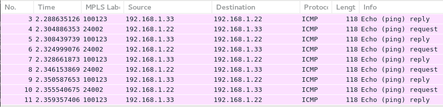
As you see, there is only MPLS service label visible as both Arista and Cisco IOS XR performs PHP.
#2. EOS2 to SR1
The second case is to check the connectivity between Arista EOS2 and Nokia SR1:
2
3
4
5
6
7
8
9
10
PING 192.168.1.11 (192.168.1.11) 72(100) bytes of data.
80 bytes from 192.168.1.11: icmp_seq=1 ttl=64 time=18.5 ms
80 bytes from 192.168.1.11: icmp_seq=2 ttl=64 time=24.1 ms
80 bytes from 192.168.1.11: icmp_seq=3 ttl=64 time=27.9 ms
80 bytes from 192.168.1.11: icmp_seq=4 ttl=64 time=29.9 ms
80 bytes from 192.168.1.11: icmp_seq=5 ttl=64 time=30.3 ms
--- 192.168.1.11 ping statistics ---
5 packets transmitted, 5 received, 0% packet loss, time 76ms
rtt min/avg/max/mdev = 18.547/26.194/30.397/4.407 ms, pipe 2, ipg/ewma 19.095/22.641 ms
Again, the connectivity is working perfectly fine so we can take a look on wire:

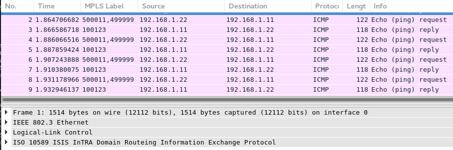
Here you see the different situation comparing to the previous one, as Nokia SR OS doesn’t perform PHP by default, hence we you see EOS2 sending packets to SR1 with 2 labels (transport level segment routing and service level BGP).
#3. SR1 to XR3
The last but not least is the communication between Nokia SR1 and Cisco XR3:
2
3
4
5
6
7
8
9
10
11
12
13
INFO: CLI #2051: Switching to the classic CLI engine
A:SR1# /ping router-instance "CUST" 192.168.1.33
PING 192.168.1.33 56 data bytes
64 bytes from 192.168.1.33: icmp_seq=1 ttl=255 time=6.90ms.
64 bytes from 192.168.1.33: icmp_seq=2 ttl=255 time=93.1ms.
64 bytes from 192.168.1.33: icmp_seq=3 ttl=255 time=3.62ms.
64 bytes from 192.168.1.33: icmp_seq=4 ttl=255 time=48.9ms.
64 bytes from 192.168.1.33: icmp_seq=5 ttl=255 time=4.01ms.
---- 192.168.1.33 PING Statistics ----
5 packets transmitted, 5 packets received, 0.00% packet loss
round-trip min = 3.62ms, avg = 31.3ms, max = 93.1ms, stddev = 35.3ms
INFO: CLI #2052: Switching to the MD-CLI engine
As you see, in Nokia SR OS 16.0.R* another command is used for ping out of VRF comparing to previous.

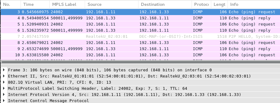
From the Wireshark we see the expected output: 2 labels from XR3 to SR1, and one label back
All the verifications are done and our multivendor network with Nokia (Alcatel-Lucent) SR OS, Cisco IOS XR and Arista EOS network functions running ISIS with Segment Routing and BGP/MPLS VPN (IP VPN) on top are fully interoperable.
Final configuration files you can find at my GitHub page.


Lessons learned
Testing is a key answer for all interoperability questions. It’s not given that all the vendors will work with each other without problems. On the other side, you will never now, if they don’t until you test it.
Don’t be afraid and test your multi-vendor scenario. In the 99% cases you can get it working
Conclusion
So far we’ve done recap of Segment Routing with ISIS and IP VPN as an MPLS service on top. It’s working pretty well across Arista EOS, Nokia (Alcatel-Lucent) SR OS and Cisco IOS XR. In the next article we’ll take a look on Segment Routing with EVPN in the same multivendor environment. Take care and good bye!
Support us
P.S.
If you have further questions or you need help with your networks, I’m happy to assist you, just send me message. Also don’t forget to share the article on your social media, if you like it.
BR,
Anton Karneliuk