


Hello my friend,
We continue building the next-generation Service Provider network with Segment Routing asMPLS data plane. Today we’ll focus on multipoint L2 VPN implemented using EVPN.
2
3
4
5
retrieval system, or transmitted in any form or by any
means, electronic, mechanical or photocopying, recording,
or otherwise, for commercial purposes without the
prior permission of the author.
Brief description
Recently we’ve covered the configuration of IP VPN services for Nokia SR OS, Cisco IOS XR and Arista EOS over Segment Routing. IP VPN services are super important in service provider network, but they aren’t the single one. That’s why we want to complement those services with L2 VPN.
To do this, we’ll use EVPN as, perhaps, the best technology today for building different L2VPNs (E-LAN, E-LINE). It can also be used for deployment of L3 VPN. The good thing, we’ve already worked a lot with EVPN in conjunction with VXLAN data plane in data center series , so I hope you are either familiar with it or can learn about it on the provided link. Everything we need to do is to “just change” VXLAN to MPLS data plane. In reality, there are a lot of changes in the packet forwarding caused by MPLS nature. The configuration is also a different, and that is exactly our focus.
What are wegoing to test?
We’ll build multipoint L2 VPN using EVPN to provide L2 connectivity between the customers connected to PE routers based on Nokia (Alcatel-Lucent) SR OS, Arista EOS and Cisco IOS XR.
At thistime, I don’t know if everything will work, especially for Cisco IOS XRv aspreviously (i.e. in version Cisco IOS XR 6.1.2) it had limitations in dataplane for L2 VPNs meaning it was not working though the control plane workswithout problems. So, we’ll check that in the verification part.
Software version
The following software components are used in this lab:
- CentOS 7.5.1804 with python 2.7.5
- Ansible 2.7.0
- Nokia SR OS 16.0.R4 [guest VNF]
- Arista EOS 4.21.1.1F [guest VNF]
- Cisco IOS XR 6.5.1 [guest VNF]
- Cumulus Linux 3.7.1 [guest VNF]
Topology
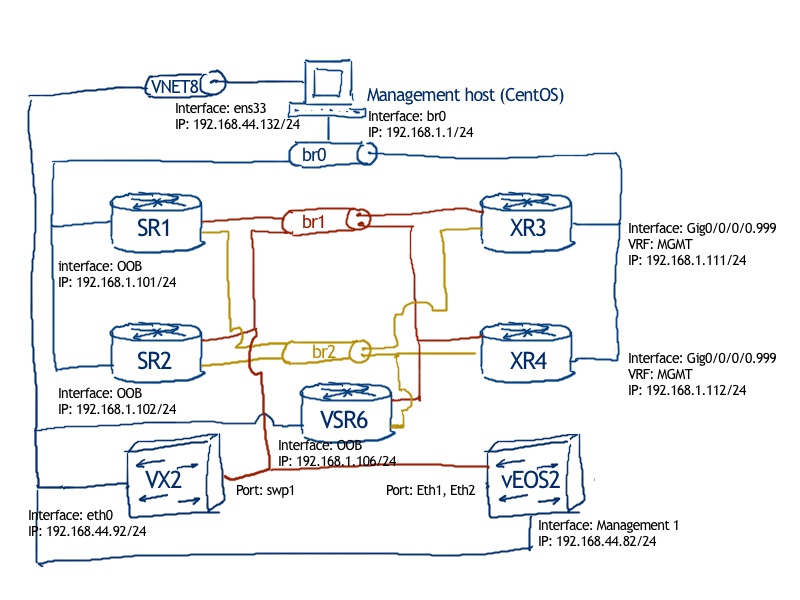
The physical topology looks as always:
See the previous article to get details how to build the lab

The logicaltopology is even simplified the topology we’ve used in the previous lab:
2
3
4
5
6
7
8
9
10
11
12
13
14
15
16
17
18
19
20
21
22
| |
| Loopbacks |
| +----------+ EOS2: L0 10.0.0.1/32 |
| | EOS1 |(Eth2)-----------+ EOS1: L0 10.0.0.22/32 |
| +----------+ .22 | XR1: L0 10.0.0.33/32 |
| (Eth1) | .1 SR1: system 10.0.0.44/32 |
| | .22 (Eth1) |
| | +----------+ +----------+ |
| | | EOS2 |(Eth3)----------------(Eth3)| SR1 | |
| | +----------+ .1 .44 +----------+ |
| | .33 (Eth2) |
| (G0/0/0/0) | .1 |
| +----------+ | |
| | XR1 |(G0/0/0/1)-------+ |
| +----------+ .33 |
| |
| ISIS 0 (CORE) / level-2 / Segment Routing |
| |
| ASN: 65000 |
| |
+-------------------------------------------------------------------------------------+
From the routing prospective the topology is relatively easy, so we have 3 PE routers (each coming from its own vendor) and one P router based on Arista vEOS-lab as there is no specific actions required, just ISIS and Segment Routing and Arista vEOS-lab requires the least amount of resources (2 GB RAM) comparing with Cisco IOS XRv 6.5.1 (4 GB RAM) or Nokia VSR (4 GB RAM).
The direct link between PEs EOS1 and XR1 shouldn’t be used by default, only in case of failure of PE-P links, hence the ISIS metric is modified to 100 on this link. The rest metrics are default.
Besides the ISIS level 2 with Segment Routing extension, which spans all the PE and Prouters, there is a BGP (iBGP fashion in AS 65000) for EVPN address-family running between loopbacks of all PE routers.
Initial configuration you can find on my GitHub page. Actually the previous topology is updated to reflect the new topology, whereas the old topology and configuration files are backed up.
Configuration of underlay infrastructure for Arista, Cisco, Nokia: ISIS and Segment Routing
The details of the configuration and verification of MPLS underlay using ISIS and Segment Routing was covered in the previous article. Please, refer there for more details. Below you find just the proper configuration for all routers followed by verification of reachability between loopbacks.
Configuration of EOS2: P router running Arista EOS
2
3
4
5
6
7
8
9
10
11
12
13
14
15
16
17
18
19
20
21
22
23
24
25
26
27
28
29
30
31
32
33
34
35
36
! Command: show running-config
! device: EOS1 (vEOS, EOS-4.21.1.1F)
!
mpls ip
!
router isis CORE
net 49.0000.0100.0000.0001.00
is-type level-2
log-adjacency-changes
advertise passive-only
!
address-family ipv4 unicast
!
segment-routing mpls
router-id 10.0.0.1
no shutdown
prefix-segment 10.0.0.1/32 index 1
!
interface Ethernet1
isis enable CORE
isis network point-to-point
!
interface Ethernet2
isis enable CORE
isis network point-to-point
!
interface Ethernet3
isis enable CORE
isis network point-to-point
!
interface Loopback0
isis enable CORE
isis passive
!
end
Configuration of EOS1: PE router running Arista EOS
2
3
4
5
6
7
8
9
10
11
12
13
14
15
16
17
18
19
20
21
22
23
24
25
26
27
28
29
30
31
32
33
! Command: show running-config
! device: EOS1 (vEOS, EOS-4.21.1.1F)
!
mpls ip
!
router isis CORE
net 49.0000.0100.0000.0022.00
is-type level-2
log-adjacency-changes
advertise passive-only
!
address-family ipv4 unicast
!
segment-routing mpls
router-id 10.0.0.22
no shutdown
prefix-segment 10.0.0.22/32 index 22
!
interface Ethernet1
isis enable CORE
isis metric 100
isis network point-to-point
!
interface Ethernet2
isis enable CORE
isis network point-to-point
!
interface Loopback0
isis enable CORE
isis passive
!
end
Configuration of XR1: PE router running Cisco IOS XR
2
3
4
5
6
7
8
9
10
11
12
13
14
15
16
17
18
19
20
21
22
23
24
25
26
27
28
29
30
31
32
Sun Dec 16 17:55:24.243 UTC
Building configuration...
!! IOS XR Configuration 6.5.1.34I
router isis CORE
is-type level-2-only
net 49.0000.0100.0000.0033.00
log adjacency changes
address-family ipv4 unicast
metric-style wide
advertise passive-only
segment-routing mpls sr-prefer
!
interface Loopback0
passive
address-family ipv4 unicast
prefix-sid index 33
!
!
interface GigabitEthernet0/0/0/0
point-to-point
address-family ipv4 unicast
metric 100
!
!
interface GigabitEthernet0/0/0/1
point-to-point
address-family ipv4 unicast
!
!
!
end
Configuration of SR1: PE router running Nokia (Alcatel-Lucent) SR OS
2
3
4
5
6
7
8
9
10
11
12
13
14
15
16
17
18
19
20
21
22
23
24
25
26
27
28
29
30
31
32
33
34
35
36
37
38
configure {
router "Base" {
+ router-id 10.0.0.44
+ mpls-labels {
+ sr-labels {
+ start 500000
+ end 523456
+ }
+ }
+ isis 0 {
+ admin-state enable
+ advertise-passive-only true
+ advertise-router-capability as
+ level-capability 2
+ area-address [49.0000]
+ segment-routing {
+ admin-state enable
+ tunnel-table-pref 8
+ prefix-sid-range {
+ global
+ }
+ }
+ interface "system" {
+ passive true
+ ipv4-node-sid {
+ index 44
+ }
+ }
+ interface "toEOS2" {
+ interface-type point-to-point
+ }
+ level 2 {
+ wide-metrics-only true
+ }
+ }
}
}
Verification
The next step is to configure MP-BGP peering between loopbacks/system interfaces, that’s why we need to check they are reachable:
2
3
4
5
6
7
8
9
10
11
12
13
14
15
16
17
18
19
20
21
22
23
24
Sun Dec 16 18:05:46.490 UTC
Type escape sequence to abort.
Sending 5, 100-byte ICMP Echos to 10.0.0.1, timeout is 2 seconds:
!!!!!
Success rate is 100 percent (5/5), round-trip min/avg/max = 9/9/9 ms
RP/0/0/CPU0:XR1#ping 10.0.0.22 so lo0
Sun Dec 16 18:05:49.540 UTC
Type escape sequence to abort.
Sending 5, 100-byte ICMP Echos to 10.0.0.22, timeout is 2 seconds:
!!!!!
Success rate is 100 percent (5/5), round-trip min/avg/max = 29/35/59 ms
RP/0/0/CPU0:XR1#ping 10.0.0.33 so lo0
Sun Dec 16 18:05:52.650 UTC
Type escape sequence to abort.
Sending 5, 100-byte ICMP Echos to 10.0.0.33, timeout is 2 seconds:
!!!!!
Success rate is 100 percent (5/5), round-trip min/avg/max = 1/1/1 ms
RP/0/0/CPU0:XR1#ping 10.0.0.44 so lo0
Sun Dec 16 18:05:55.970 UTC
Type escape sequence to abort.
Sending 5, 100-byte ICMP Echos to 10.0.0.44, timeout is 2 seconds:
!!!!!
Success rate is 100 percent (5/5), round-trip min/avg/max = 19/21/29 ms
Connectivity is there, so we can proceed further. For more option, how to check MPLS date plane, take a look on the previous article.
Configurationof underlay infrastructure for Arista, Cisco, Nokia: BGP for EVPN
From now onthe configuration will be performed only on PE routers, whereas P will be untouched. The next step is to establish BGP peering between all the PEs for EVPN address-family (AFI/SAFI 25/70). The session is build using addresses of the loopback0/system interfaces.
Configuration of SR1: PE router running Nokia (Alcatel-Lucent) SR OS
2
3
4
5
6
7
8
9
10
11
12
13
14
15
16
17
18
19
20
21
22
23
24
25
26
27
28
29
30
31
32
33
34
A:admin@SR1# compare
configure {
router "Base" {
+ autonomous-system 65000
+ bgp {
+ next-hop-resolution {
+ labeled-routes {
+ transport-tunnel {
+ family vpn {
+ resolution filter
+ resolution-filter {
+ sr-isis true
+ }
+ }
+ }
+ }
+ }
+ group "iBGP_PEERS" {
+ peer-as 65000
+ local-address "10.0.0.44"
+ family {
+ evpn true
+ }
+ }
+ neighbor "10.0.0.22" {
+ group "iBGP_PEERS"
+ }
+ neighbor "10.0.0.33" {
+ group "iBGP_PEERS"
+ }
+ }
}
}
Configuration of EOS1: PE router running Arista EOS
2
3
4
5
6
7
8
9
10
11
12
13
14
15
16
17
18
19
20
21
22
23
24
! Command: show running-config
! device: EOS1 (vEOS, EOS-4.21.1.1F)
!
service routing protocols model multi-agent
!
router bgp 65000
router-id 10.0.0.22
neighbor iBGP_PEER peer-group
neighbor iBGP_PEER remote-as 65000
neighbor iBGP_PEER update-source Loopback0
neighbor iBGP_PEER send-community standard extended
neighbor iBGP_PEER maximum-routes 12000
neighbor 10.0.0.33 peer-group iBGP_PEER
neighbor 10.0.0.44 peer-group iBGP_PEER
!
address-family evpn
neighbor default encapsulation mpls next-hop-self source-interface Loopback0
neighbor iBGP_PEER activate
!
address-family ipv4
no neighbor iBGP_PEER activate
!
end
Don’t forget to enable ArBGP in Arista EOS (tie first command in the output above).
Configuration of XR1: PE router running Cisco IOS XR
2
3
4
5
6
7
8
9
10
11
12
13
14
15
16
17
18
19
20
21
22
23
24
25
26
27
28
29
Sun Dec 16 18:22:55.660 UTC
Building configuration...
!! IOS XR Configuration 6.5.1.34I
router bgp 65000
bgp router-id 10.0.0.33
bgp log neighbor changes detail
address-family l2vpn evpn
!
af-group AG_iBGP_PEER_EVPN address-family l2vpn evpn
!
session-group SG_iBGP_PEER
remote-as 65000
update-source Loopback0
!
neighbor-group NG_iBGP_PEER
use session-group SG_iBGP_PEER
address-family l2vpn evpn
use af-group AG_iBGP_PEER_EVPN
!
!
neighbor 10.0.0.22
use neighbor-group NG_iBGP_PEER
!
neighbor 10.0.0.44
use neighbor-group NG_iBGP_PEER
!
!
end
Verification
We don’t advertise any routes yet, therefore we can only check if the BGP peering is established. Here is the relevant output from CiscoIOS XR based PE XR1:
2
3
4
5
6
7
8
9
10
11
12
13
14
15
16
17
18
19
20
21
Sun Dec 16 18:41:55.702 UTC
BGP router identifier 10.0.0.33, local AS number 65000
BGP generic scan interval 60 secs
Non-stop routing is enabled
BGP table state: Active
Table ID: 0x0 RD version: 0
BGP main routing table version 1
BGP NSR Initial initsync version 1 (Reached)
BGP NSR/ISSU Sync-Group versions 0/0
BGP scan interval 60 secs
BGP is operating in STANDALONE mode.
Process RcvTblVer bRIB/RIB LabelVer ImportVer SendTblVer StandbyVer
Speaker 1 1 1 1 1 0
Neighbor Spk AS MsgRcvd MsgSent TblVer InQ OutQ Up/Down St/PfxRcd
10.0.0.22 0 65000 27 25 1 0 0 00:07:17 0
10.0.0.44 0 65000 40 39 1 0 0 00:18:30 0
To reduce the length of the article, here is just example of the commands delivering the same information about BGP peering for EVPN address-family on two other PEs:
2
3
Nokia SR OS: A:admin@SR1# show router bgp summary
After the underlying infrastructure is configured, we are ready to deploy the customer services.
Configurationof overlay services for Arista, Cisco, Nokia: EVPN based multipoint L2 VPN
The following service topology is design for the customer:
2
3
4
5
6
7
8
9
10
11
12
13
14
15
16
17
18
19
20
21
22
23
24
25
26
| |
| +-----------------+ +-----------------+ |
+--+------+ |VLAN 22 | |VPLS L2VPN | +----+----+
| CUST1 |(Vlan22)--------(Eth3)|RD: 10.0.0.22:234| |RD: 10.0.0.44:234|(1/1/c2/1:44)---(Vlan44)| CUST3 |
+--+------+ .22 |RT: 65000:234 | |RT: 65000:234 | .44 +----+----+
| +------+----------+ +----------+------+ |
| | EOS1 +----------+ SR1 | |
| +----+-----+ +----+-----+ |
| | | |
| | MPLS (SR-ISIS) | |
| | +----------+ | |
| +-----+ XR1 +----+ |
| +-----------------+ |
| |VLAN 33 | |
| |RD: 10.0.0.33:234| |
| |RT: 65000:234 | |
| +-----------------+ |
| L2 Domain (G0/0/0/2) |
| IP: 192.168.0.0/24 | |
| | |
| | .33 |
| (Vlan33) |
| +---------+ |
+-----------------------------------------------+ CUST2 +------------------------------------------------+
+---------+
As you can see, each customer has its own VLAN, which is used for interconnect between CEand PE, hence appropriate configuration on the EVPN instance (either VLAN normalization or VLAN removal) should be done. From the customer prospective, the CE are residing in the same subnet 192.168.0.0/24, and that’s expected that customer sites will reach each other. Basically, the next list of activities should be done:
- Create L2 VPN context assigning name and EVI
- Associate customers’ attachment circuit (AC) with it
- Configure proper BGP parameters (RD, RT)
To do that, the following configuration is applied for PE routers.
Configurationof XR1: PE router running Cisco IOS XR
2
3
4
5
6
7
8
9
10
11
12
13
14
15
16
17
18
19
20
21
22
23
24
25
26
27
28
29
30
31
32
33
34
35
36
37
Sun Dec 16 20:01:57.163 UTC
Building configuration...
!! IOS XR Configuration 6.5.1.34I
interface GigabitEthernet0/0/0/2
no shutdown
!
!
interface GigabitEthernet0/0/0/2.33 l2transport
encapsulation dot1q 33 exact
rewrite ingress tag translate 1-to-1 dot1q 22 symmetric
!
evpn
evi 234
bgp
rd 10.0.0.33:234
route-target 65000:234
!
advertise-mac
!
!
interface GigabitEthernet0/0/0/2
ethernet-segment
!
!
!
l2vpn
bridge group CUST234
bridge-domain CUST234
interface GigabitEthernet0/0/0/2.33
!
evi 234
!
!
!
!
end
Configurationof SR1: PE router running Nokia (Alcatel-Lucent) SR OS
2
3
4
5
6
7
8
9
10
11
12
13
14
15
16
17
18
19
20
21
22
23
24
25
26
27
28
29
30
31
32
33
34
35
36
37
38
39
40
41
42
43
44
45
A:admin@SR1# compare
configure {
+ service {
+ vpls "CUST234" {
+ admin-state enable
+ service-id 100234
+ customer "1"
+ bgp 1 {
+ route-distinguisher "10.0.0.44:234"
+ route-target {
+ export "target:65000:234"
+ import "target:65000:234"
+ }
+ }
+ bgp-evpn {
+ evi 234
+ mpls 1 {
+ admin-state enable
+ force-vc-forwarding vlan
+ control-word true
+ send-tunnel-encap {
+ mpls true
+ }
+ auto-bind-tunnel {
+ resolution filter
+ resolution-filter {
+ sr-isis true
+ }
+ }
+ }
+ }
+ sap 1/1/c2/1:44 {
+ ingress {
+ qtag-manipulation {
+ push-dot1q-vlan 22
+ }
+ }
+ stp {
+ admin-state disable
+ }
+ }
+ }
+ }
}
Configurationof EOS1: PE router running Arista EOS
2
3
4
5
6
7
8
9
10
11
12
13
14
15
16
17
18
19
! Command: show running-config
! device: EOS1 (vEOS, EOS-4.21.1.1F)
!
vlan 22
name CUST234
!
interface Ethernet3
switchport trunk allowed vlan 22
switchport mode trunk
!
router bgp 65000
vlan 22
rd 10.0.0.22:234
route-target both 65000:234
redistribute learned
!
!
end
Verification
As you can see, the configuration is quite basic. The only complex part is the tag rewrite on the AC interfaces on Nokia (Alcatel-Lucent) SR OS based PE SR1 and Cisco IOSXR based PE XR1. The reasons why it’s done you can find in the “Lessons learned” section.
There are not too many things we can verify without the connected customers. But there is one, which is the distribution of the Type-3 EVPN route (inclusive-multicast). The following output is collected on Arista EOS based PE router EOS1:
2
3
4
5
6
7
8
9
10
11
12
13
14
15
16
BGP routing table information for VRF default
Router identifier 10.0.0.22, local AS number 65000
Route status codes: s - suppressed, * - valid, > - active, # - not installed, E - ECMP head, e - ECMP
S - Stale, c - Contributing to ECMP, b - backup
% - Pending BGP convergence
Origin codes: i - IGP, e - EGP, ? - incomplete
AS Path Attributes: Or-ID - Originator ID, C-LST - Cluster List, LL Nexthop - Link Local Nexthop
Network Next Hop Metric LocPref Weight Path
* > RD: 10.0.0.22:234 imet 10.0.0.22
- - - 0 i
* > RD: 10.0.0.33:234 imet 10.0.0.33
10.0.0.33 - 100 0 i
* > RD: 10.0.0.44:234 imet 10.0.0.44
10.0.0.44 0 100 0 i
The following commands can be used on two other operation systems from our review:
2
3
Cisco IOS XR: RP/0/0/CPU0:XR1#show bgp l2vpn evpn bridge-domain CUST234
As long as the configuration in the service provider networkis done, we can try to provide the service for the customer and try to test, if it works. As you know, the ultimate success of any configuration exercise in the network field is the happy customer, which gets his/her service.
Providingthe service to the customer: EVPN based L2 multipoint (E-LAN)
The customer’s connectivity is simulated by Cumulus Linux based CE VX4. It uses the least amount of resources (1 GB RAM), therefore it’s perfectly matching the need of this setup. The customer’s connectivity looks as follows:
2
3
4
5
6
7
8
9
10
11
12
13
14
15
16
17
| | / /
| +----+-------+ 192.168.0.0/24 +---------+ \
| | VRF: CUST1 |(VLAN22/swp1)-----------(Eth3-trunk)| EOS1 | /
| +----+-------+ .22 +---------+ M \
| | \ P /
| | / L \
| V +----+-------+ 192.168.0.0/24 +---------+ S /
| X | VRF: CUST2 |(VLAN33/swp2)----------(G0/0/0/2.33)| XR1 | \
| 4 +----+-------+ .33 +---------+ C /
| | \ O \
| | / R /
| +----+-------+ 192.168.0.0/24 +---------+ E \
| | VRF: CUST3 |(VLAN44/swp3)-------(sap1/1/c2/1:44)| SR1 | /
| +----+-------+ .44 +---------+ \
| | \ /
+----------+ \/\/\/\/\/
According to such topology it’s necessary to create only VRFs, interfaces VLAN with proper IP addresses and properly map them per physical port.
Configuration of VX4: CE router running Cumulus Linux
2
3
4
5
6
7
8
9
10
11
12
13
14
15
16
17
18
19
20
21
22
23
24
25
26
27
28
29
30
31
32
33
34
35
36
37
38
39
40
41
42
43
44
45
interface swp1
bridge-vids 22
interface swp2
bridge-vids 33
interface swp3
bridge-vids 44
interface CUST1
vrf-table auto
interface CUST2
vrf-table auto
interface CUST3
vrf-table auto
interface bridge
bridge-ports swp1 swp2 swp3
bridge-vids 22 33 44
bridge-vlan-aware yes
interface vlan22
address 192.168.0.22/24
hwaddress 00:FF:5E:00:00:22
vlan-id 22
vlan-raw-device bridge
vrf CUST1
interface vlan33
address 192.168.0.33/24
hwaddress 00:FF:5E:00:00:33
vlan-id 33
vlan-raw-device bridge
vrf CUST2
interface vlan44
address 192.168.0.44/24
hwaddress 00:FF:5E:00:00:44
vlan-id 44
vlan-raw-device bridge
vrf CUST3
More information about configuration of Cumulus Linux you can find in the proper article.
Verification
We start straight with the key point, which is data plane verification using ICMP ping:
2
3
4
5
6
7
8
9
10
11
12
13
14
15
16
17
18
19
20
21
22
23
24
25
26
27
ping: Warning: source address might be selected on device other than CUST1.
PING 192.168.0.22 (192.168.0.22) from 192.168.0.22 CUST1: 56(84) bytes of data.
64 bytes from 192.168.0.22: icmp_seq=1 ttl=64 time=0.018 ms
64 bytes from 192.168.0.22: icmp_seq=2 ttl=64 time=0.093 ms
64 bytes from 192.168.0.22: icmp_seq=3 ttl=64 time=0.051 ms
--- 192.168.0.22 ping statistics ---
3 packets transmitted, 3 received, 0% packet loss, time 2000ms
rtt min/avg/max/mdev = 0.018/0.054/0.093/0.030 ms
cumulus@VX4:mgmt-vrf:~$ ping -I CUST1 192.168.0.33 -c 3
ping: Warning: source address might be selected on device other than CUST1.
PING 192.168.0.33 (192.168.0.33) from 192.168.0.22 CUST1: 56(84) bytes of data.
--- 192.168.0.33 ping statistics ---
3 packets transmitted, 0 received, 100% packet loss, time 2009ms
cumulus@VX4:mgmt-vrf:~$ ping -I CUST1 192.168.0.44 -c 3
ping: Warning: source address might be selected on device other than CUST1.
PING 192.168.0.44 (192.168.0.44) from 192.168.0.22 CUST1: 56(84) bytes of data.
64 bytes from 192.168.0.44: icmp_seq=1 ttl=64 time=47.3 ms
64 bytes from 192.168.0.44: icmp_seq=2 ttl=64 time=53.3 ms
64 bytes from 192.168.0.44: icmp_seq=3 ttl=64 time=42.3 ms
--- 192.168.0.44 ping statistics ---
3 packets transmitted, 3 received, 0% packet loss, time 2005ms
rtt min/avg/max/mdev = 42.339/47.675/53.310/4.487 ms
As you can see from the output below, the connectivity between customer sites connected to PEs running Arista EOS and Nokia (Alcatel-Lucent) SR OS is successful. The site connected to Cisco IOS XR based PE isn’t reachable.
You might remember that Cisco IOS XRv has limitations in data plane for L2 VPNs.
The good thing is that in general connectivity over EVPN service over Segment Routing is working. So, let’s verify some “show” commands on different operation systems.
The first important point is the data plane information, like the association of MAC addresses with EVPN cloud or ACs, how it’s shown on Nokia (Alcatel-Lucent) SR OS router SR1:
2
3
4
5
6
7
8
9
10
11
12
13
14
15
16
17
A:admin@SR1# show service id "100234" fdb detail
===============================================================================
Forwarding Database, Service 100234
===============================================================================
ServId MAC Source-Identifier Type Last Change
Age
-------------------------------------------------------------------------------
100234 00:ff:5e:00:00:22 eMpls: Evpn 12/16/18 19:52:22
10.0.0.22:1040210
100234 00:ff:5e:00:00:44 sap:1/1/c2/1:44 L/0 12/16/18 19:51:19
-------------------------------------------------------------------------------
No. of MAC Entries: 2
-------------------------------------------------------------------------------
Legend: L=Learned O=Oam P=Protected-MAC C=Conditional S=Static Lf=Leaf
===============================================================================
To extract the same configuration from Cisco IOS XR and Arista EOS use the following commands:
2
3
Cisco IOS XR: RP/0/0/CPU0:XR1#show evpn evi vpn-id 234 mac
You can see that Cisco IOS XR based PE XR1 even hasn’t learned the MAC address of the host connected to its “gig0/0/0/0.33” port.
The next important step is to check the BGP routing table to review the routes. Actually, we should have done it earlier, before checking the data plane, but as we have started with the ping, the control plane appears to be in the end. So, BGP RIB for EVPN address-family (AFI/SAFI 25/70) looks as follows:
2
3
4
5
6
7
8
9
10
11
12
13
14
15
16
17
18
19
20
21
22
23
24
25
26
27
28
29
Sun Dec 16 21:23:29.308 UTC
BGP router identifier 10.0.0.33, local AS number 65000
BGP generic scan interval 60 secs
Non-stop routing is enabled
BGP table state: Active
Table ID: 0x0 RD version: 0
BGP main routing table version 34
BGP NSR Initial initsync version 1 (Reached)
BGP NSR/ISSU Sync-Group versions 0/0
BGP scan interval 60 secs
Status codes: s suppressed, d damped, h history, * valid, > best
i - internal, r RIB-failure, S stale, N Nexthop-discard
Origin codes: i - IGP, e - EGP, ? - incomplete
Network Next Hop Metric LocPrf Weight Path
Route Distinguisher: 10.0.0.33:234 (default for vrf CUST234)
*>i[2][0][48][00ff.5e00.0022][0]/104
10.0.0.22 100 0 i
*>i[2][0][48][00ff.5e00.0044][0]/104
10.0.0.44 0 100 0 i
*>i[3][0][32][10.0.0.22]/80
10.0.0.22 100 0 i
*> [3][0][32][10.0.0.33]/80
0.0.0.0 0 i
*>i[3][0][32][10.0.0.44]/80
10.0.0.44 0 100 0 i
Processed 5 prefixes, 5 paths
Nokia (Alcatel-Lucent) SR OS and Arista EOS has the following commands to provide you that info:
2
3
4
Nokia SR OS: A:admin@SR1# show router bgp neighbor 10.0.0.22 filter1 advertised-routes family evpn
Arista EOS: EOS1#show bgp evpn extcommunity rt 65000:234
For Nokia there is no general view for BGP-RIB, hence we verify separately Adj-Rib-In and Adj-Rib-Out.
Here we go. We have configured EVPN with BGP control plane running over Segment Routing MPLS data plane. That’s exactly how the modern network should be built today and tomorrow.
The final configurations as well as topology files you can find on my GitHub

Lessons learned
In the very beginning nothing has worked. I thought, that probably EVI is missing on Arista EOS side, as it isn’t configured somewhere. But some troubleshooting with Wireshark told me different story. When the packets are sent by Arista EOS based PE EOS2, then the packet looks like as follows:

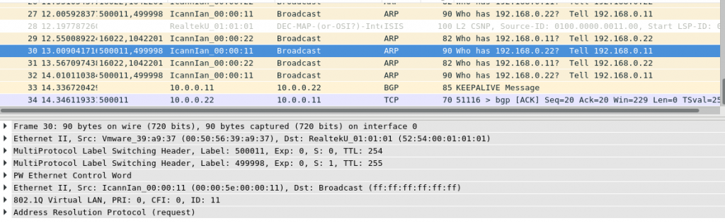
When the packetis sent by Nokia (Alcatel-Lucent) SR OS based PE SR1, then we have 2 less headers:

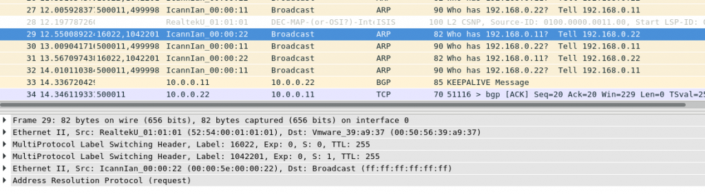
Therefore, the solution is either to enable control word and VLAN tag propogation on Nokia, or disable both on Arista, or mix. The following solution is applied to fix that:
2
3
4
5
6
7
8
9
10
11
12
13
14
15
16
17
18
19
20
21
22
configure {
service {
vpls "L2_VNI" {
bgp-evpn {
mpls 1 {
force-vc-forwarding vlan
}
}
sap 1/1/c2/1:22 {
ingress {
qtag-manipulation {
push-dot1q-vlan 11
}
}
stp {
admin-state disable
}
}
}
}
}
The similar trick was applied on Cisco IOS XR:
2
3
4
5
6
7
8
9
10
11
Sun Dec 16 21:39:10.303 UTC
Building configuration...
!! IOS XR Configuration 6.5.1.34I
!! Last configuration change at Sun Dec 16 20:18:57 2018 by cisco
!
interface GigabitEthernet0/0/0/2.33 l2transport
encapsulation dot1q 33 exact
rewrite ingress tag translate 1-to-1 dot1q 22 symmetric
!
end
Unfortunately, I wasn’t able to check, if it’s working, as it data plane for L2 VPNs is in general broken on Cisco IOS XRv.
Conclusion
In the article today we’ve reviewed the configuration of EVPN for L2 VPN over MPLS in Service Provider network. Such scenario could be used for DCI or even when we build IP fabric in date center (link) using MPLS instead of VXLAN. Also we had some fun with the troubleshooting as different vendors have different default behavior. That’s why I’m writing my block, to show you how different vendorscan work together.
In the next article we’ll talk about EVPN for L3 VPN over Segment Routing. Take care and good bye!
Support us
P.S.
If you have further questions or you need help with your networks, I’m happy to assist you, just send me message. Also don’t forget to share the article on your social media, if you like it.
BR,
Anton Karneliuk