

Hello my friend,
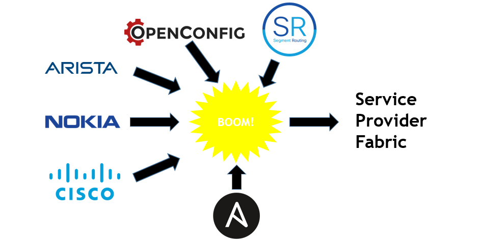
I hope you have wonderful Christmas break and now you are coming back fully energized to rock in 2019. Today we are going to automate service provider network (or how I called it Service Provider Fabric, read below why) in terms of underlay configuration in multi-vendor environment with Cisco IOS XR, Nokia SR OS and Arista EOS network functions.
2
3
4
5
retrieval system, or transmitted in any form or by any
means, electronic, mechanical or photocopying, recording,
or otherwise, for commercial purposes without the
prior permission of the author.
Brief description
In 2018 we are talked a lot about modern data center architecture running EVPN/VXLAN. As you know, the traditional network business in general is to transmit the traffic from one application to another. In data center context the major focus is on the different components of applications, like front-end/back-end services, various data bases and so on. Regardless of their nature meaning whether they are virtualized or not, there are typically 2 types of the traffic between components of applications:
- L2 (pure Ethernet, communication within the same broadcast domain/IP Subnet)
- L3 (internetworking, communication between different broadcast domains/IP Subnets)
Data centers have a long development history to current state, starting with VLAN segmentation, STP and routing functions in core to present state, where gateway function is distributed across all Leaf switches (or even hypervisors). The actual service is called “overlay” and is realized using BGP-EVPN signaling with VXLAN encapsulation. The service itself is decoupled from network infrastructure called “underlay”, which main function is to provide connectivity between service termination endpoints (VTEP for VXLAN). Typically, the architecture is 2-Tier with “leaf” switches, which terminate overlay services, and “spine” switches, which performs pure packet forwarding. One “leaf” switch is connected to multiple “spine” switches for load-sharing and resiliency. Such architecture is called “Clos” or “IP fabric”. For more complex scenarios, like hyper-scale data centers or data center interconnect (DCI), the “fabric” could contain 3,4 and more tiers.
Read more details about data center architecture and configuration for Cisco, Nokia, Cumulus and Arista.
If we think for a moment, we can spot that today there is almost no difference in the architecture of the data center and service provider networks (we discussed it once previously), as the key components are similar:
- Services: both provides the same set of services (L2 and L3 connectivity over the network)
- Components: both have service termination network functions (leaf for DC and PE for SP) and transit nodes (spine for DC and P for SP) performing absolutely similar functions
- Media: both are using Ethernet. Though SP has still legacy interface type like E1 or STM, but that is being deprecated now and all the communication is de-facto Ethernet/IP today
Having said that, it’s also to fair to highlight the differences themselves:
- Latency: service provider network is built across distant geographical locations, hence different links have different lengths causing different signal propagation, what is critical for applications like voice/video communication, online-gaming, tactile internet and so on. All that is not relevant for data center, as all the components are located together in the same or close buildings and the lengths of the leaf-spine links are negligible (we don’t touch the example of geo-redundant data centers, which has strict demand to latency for online DB replication).
- Bandwidth: Price of 100G interfaces in data centers are much lower comparing to WAN 100G interfaces. This is also accompanied by the ease of new link installation in data center, as there are no such expenses as digging the ground to lay new cable, install DWDM equipment and so on, what exists in service provider world.
These two facts create additional requirements to service provider network, which aren’t presented in data center world: traffic engineering and QoS.
Summarizing all the information above, the architecture of the data center and service provider network is very similar, that’s why I called it “Service Provider Fabric”. Following the same terminology used for data centers, what makes absolutely sense for me, we have the following building blocks:
- Underlay: routing protocol ISIS provides connectivity between all the Service Provider Fabric elements. As encapsulation for services MPLS is used, therefore ISIS is extended by Segment Routing, which has possibility to perform best-effort routing/load-sharing, where it’s enough, or traffic-engineering, where latency or guaranteed BW is critical. MP-BGP for address-families VPNV4/VPNV6 unicast (AFI/SAFI 1/128 and 2/128) together with L2VPN EVPN (AFI/SAFI 25/70) is used to signal the customer L2 and L3 services.
- Overlay: based on the mentioned address families for BGP, IP-VPN is used to signal L3 (IPv4/IPv6) customer services, whereas EVPN is used for L2 (E-LAN and E-LINE). Based on the vendor development, we’ll enable L3 services over EVPN as well, what is good working for VXALN in data center now, but in MPLS world some vendors have yet some work to do
That is our Service Provider Fabric. We already shared some examples of IP-VPN and EVPN (E-LAN). There were some minor changes in the topology, that’s why you should always check the most resent state on my GitHub page.
The Service Provider Fabric is multivendor consisting of Arista EOS, Cisco IOS XR and Nokia (Alcatel-Lucent) EOS router with Cumulus Linux acting as CE.
What are we going to test?
The configuration of ISIS with Segment Routing for Nokia, Arista and Cisco as well as BGP configuration was already shown. That’s why it isn’t focus.
In the focus there are two things:
- Automation: to automate the deployment of underlay configuration (ISIS, Segment Routing and MP-BGP) in multivendor environment, so that network function initially has only management port up and connectivity to management host
- Openness: to use only open-source or free of charge tools and YANG models publically available in the internet.
The latter is important, because for Nokia SR OS the YANG modules aren’t published anywhere officially, therefore I don’t use them as I am not allowed to put them to GitHub. On the other hand, Cisco IOS XR YANG modules and Arista EOS YANG modules are officially published, I just copied corresponding modules to my GitHub, because, as you will see later, original YANG modules are used for automation of the network functions configuration.
Nevertheless, it doesn’t mean that we can’t use NETCONF/YANG on Nokia (Alcatel-Lucent) SR OS network functions, as we have already used it many times. It means that we would need to perform the configuration via CLI, then extract the configuration using NETCONF in XML format and then create Jinja2 template of XML file, which in future will be used for NETCONF configuration. We’ll do that in future, as it requires some time, but for now we stay CLI-based automation via Ansible sros_config module.
Moreover, Nokia doesn’t support Segment Routing in OpenConfig YANG modules currently, so we will have to use Nokia native YANG modules.
Software version
The following software components are used in this lab:
- CentOS 7.5.1804 with python 2.7.5
- Ansible 2.7.0
- Nokia SR OS 16.0.R4 [guest VNF]
- Arista EOS 4.21.1.1F [guest VNF]
- Cisco IOS XR 6.5.1 [guest VNF]
- Cumulus Linux 3.7.1 [guest VNF]
See the previous article to get details how to build the lab
Topology
Starting from now I’m shifting all the schemes in ASCII format. The reason for that is quite simple. I’m manly developing all the automation from CLI in Linux, and having the topology in ASCII format provides me possibility to view it directly in CLI without necessity to switch to any other application, what is very convenient and saves the time. So the management topology looks like the following:
2
3
4
5
6
7
8
9
10
11
12
13
14
15
16
17
| |
| +-------------+ +-----------------+ |
| | Internet GW | | management host | |
| +------+------+ +--------+--------+ |
| | eth1 | ens33 |
| | .2 | .131 OOB: 192.168.141.0/24 |
| | | |
| +---+-----------+--------------+--------------+-------------+ |
| | | | | | |
| | BOF (Eth) | MgmtEth0 | Management1 | Management1 | eth0 |
| | .101 | .51 | .71 | .72 | .84 |
| +---+---+ +---+---+ +---+---+ +---+---+ +---+---+ |
| | SR1 | | XR1 | | EOS1 | | EOS2 | | VX4 | |
| +-------+ +-------+ +-------+ +-------+ +-------+ |
| |
+---------------------------------------------------------------------------+
Previously this topology was called “physical topology”, but after creating cheat sheet for KVM, it doesn’t matter anymore which hypervisor are you using: KVM, VMware Workstation or Oracle VirtualBox.
The logical topology is the same, as it was used in the previous lab, but more informative this time including IP subnets for interconnect links and SIDs for Segment Routing:
2
3
4
5
6
7
8
9
10
11
12
13
14
15
16
17
18
19
20
21
22
23
24
25
26
27
28
29
30
31
32
33
| |
| L0: |
| 10.0.0.22/32 |
| fc00::10:0:0:22/128 10.1.22.0/24 |
| (Metric: 10) fc00::10:1:22:0/112 |
| +---------------+ (Metric: 10) |
| | EOS1 (SID:22) |(Eth2)+----------------------+ |
| +---------------+ .22/:22 | |
| (Eth1) | |
| + .22/:22 + .1/:1 10.1.44.0/24 |
| | (Eth1) fc00::10:1:44:0/112 |
| | 10.22.33.0/24 +--------------+ (Metric: 10) +----------------+ |
| | fc00::10:22:33:0/112 | EOS2 (SID:1) |(Eth3)+--------------+(Eth3)| SR1 (SID: 44) | |
| | (Metric: 100) +--------------+ .1:/1 .44/:44 +----------------+ |
| | (Eth2) |
| + .33/:33 + .1/:1 L0: system: |
| (G0/0/0/0) | 10.0.0.1/32 10.0.0.44/32 |
| +---------------+ | fc00::10:0:0:1/128 fc00::10:0:0:44/128 |
| | XR1 (SID:33) |(G0/0/0/1)+------------------+ (Metric: 10) (Metric: 10) |
| +---------------+ .33/:33 (Metric: 10) |
| 10.1.33.0/24 |
| L0: fc00::10:1:33:0/112 |
| 10.0.0.33/32 |
| fc00::10:0:0:33/128 |
| (Metric: 10) ISIS 0 (CORE) / level 2 / Segment Routing |
| |
| ASN: 65000 |
| |
| Full iBGP mesh for VPNV4 UNICAST, VPNV6 UNICAST |
| and L2VPN EVPN between loopbacks of all PEs |
| |
+-------------------------------------------------------------------------------------------------------------+
As you can find in the description to the topology, all 3 PE routers in this topology are coming from different vendors:
- SR1 is running Nokia (Alcatel-Lucent) SR OS
- XR1 is running Cisco IOS XR
- EOS1 is running Arista EOS
The relevant software versions were shown in the beginning of this article.
All the routers are running ISIS routing protocol with Segment Routing. The values are of interfaces metrics as well as Segment Routing SIDs are shown on the diagram above. ISIS is running in multi-topology fashion both for IPv4 and IPv6 address families. Full-mesh iBGP for VPNv4/VPNv6 unicast and EVPN is running between the loopback0 and system interfaces of the PE network functions.
The initial configuration as well as the topologies and all the automations you can find on my GitHub page.
General structure of Service Provider Fabric automation with Ansible
I strongly recommend you to visit my GitHub page to learn the hierarchy of folders and files.
As we speak about automation, I will focus only on respective folder, leaving the rest for your discovery. First of all, let’s take a high level look on the content of the folder with Ansible playbooks:
2
3
4
5
6
7
8
9
10
11
12
+--ansible
+--ansible.cfg
+--files (folder)
+--group_vars (folder)
+--hosts
+--output (folder)
+--README.md
+--roles (folder)
+--sp_sr.yml
+--vars (folder)
+--yang_extractor_config.yml
The content of the folders will be explained later in this part.
As my intention is to make Git a product compete by itself, there are a lot of “README.md” files. For example, README.md in “ansible” folder provides hints how to use playbooks and other valuable information in terms of what is supported, how the configuration is done and so on. File “ansible.cfg” has just one configuration line to remove the problem with SSH caused by constant VNF network starts, so the host key check is disabled:
2
3
[defaults]
host_key_checking = False
File “hosts” is Ansible hosts as it lists all the groups and assignment of the network functions to the groups. For the Service Provider Fabric nodes, the grouping is done by network OS version:
2
3
4
5
6
7
8
9
10
11
12
13
14
15
16
17
18
19
20
21
[management_host]
localhost
[iosxr]
XR1
[eos]
EOS1
EOS2
[sros]
SR1
[cumulus]
VX4
[fabric:children]
iosxr
eos
sros
The next important part is the platform defaults from “group_vars”, like username/passwords, network OS type as well some platform defaults (right now the label block for Segment Routing only, but could be easily extended in future in case of necessity). To reduce the length of the article, only the tree and one example for Nokia SR OS based PE SR1 is shown:
2
3
4
5
6
7
8
9
10
11
12
13
14
15
16
17
18
19
20
21
22
23
24
25
26
27
28
+--ansible
+--group_vars
+--all
| +--main.yml
+--cumulus
| +--main.yml
+--eos
| +--main.yml
+--iosxr
| +--main.yml
+--README.md
+--sros
+--main.yml
$ cat group_vars/sros/main.yml
---
ansible_user: admin
ansible_pass: admin
ansible_ssh_pass: admin
ansible_network_os: sros
platform_defaults:
mpls_label_ranges:
- id: sr
start: 500000
end: 524287
...
The variables, which are used for configuration of the network functions in the Service Provider Fabric are stored in “vars” folder. I’ve created the structure, what corresponds my needs. Again, it can be easily extended, if needed, and then the corresponding updates must be done in the Jinja2 templates (see later in the “roles”). Below you can see the tree for “vars” and example of the variables for Cisco IOS XR based PE XR1:
2
3
4
5
6
7
8
9
10
11
12
13
14
15
16
17
18
19
20
21
22
23
24
25
26
27
28
29
30
31
32
33
34
35
36
37
38
39
40
41
42
43
44
45
46
47
48
49
50
51
52
53
54
55
56
57
58
59
60
61
62
63
64
65
66
67
68
69
70
71
72
73
74
75
76
77
78
79
80
81
82
83
84
85
86
87
+--ansible
+--vars
+--EOS1_underlay.yml
+--EOS2_underlay.yml
+--README.md
+--SR1_underlay.yml
+--XR1_underlay.yml
$ cat vars/XR1_underlay.yml
---
interfaces:
- name: GigabitEthernet0/0/0/0
enabled: true
ipv4:
address: 10.22.33.33
prefix: 24
ipv6:
address: fc00::10:22:33:33
prefix: 112
- name: GigabitEthernet0/0/0/1
enabled: true
ipv4:
address: 10.1.33.33
prefix: 24
ipv6:
address: fc00::10:1:33:33
prefix: 112
- name: Loopback0
enabled: true
ipv4:
address: 10.0.0.33
prefix: 32
ipv6:
address: fc00::10:0:0:33
prefix: 128
routing:
- id: ISIS
tag: CORE
enabled: true
af:
- afi: IPV4
safi: UNICAST
- afi: IPV6
safi: UNICAST
area_id: "49.0000"
system_id: "0100.0000.0033"
is_type: LEVEL_2
advertise: passive
interfaces:
- name: Loopback0
passive: true
segment_routing:
id_type: index
id_value: 33
- name: GigabitEthernet0/0/0/0
passive: false
type: POINT_TO_POINT
metric: 100
- name: GigabitEthernet0/0/0/1
passive: false
type: POINT_TO_POINT
- id: BGP
tag: BGP
enabled: true
asn: 65000
af:
- afi: L3VPN_IPV4
safi: UNICAST
- afi: L3VPN_IPV6
safi: UNICAST
- afi: L2VPN
safi: EVPN
multipath: 4
peer_groups:
- id: IBGP_PEERS
peer_asn: 65000
neighbors:
- id: 10.0.0.22
peer_group: IBGP_PEERS
- id: 10.0.0.44
peer_group: IBGP_PEERS
mpls:
- protocol: isis-sr
enabled: true
...
Looking on the variables, you can imagine, what exactly is templated and automated.
The last piece of information I want to highlight, before talking about the core Ansible playbooks itself, is the OpenConfig YANG modules. I tried to use them wherever possible, but there are certain limitations yet (unfortunately), and as explained earlier not all the vendors not fully support them. OpenConfig YANG modules are used first of all to construct properly Jinja2 templates for JSON files and then to turn JSON files with config into proper XML structure used by NETCONF. These particular OpenConfig YANG modules were extracted via NETCONF directly from the network functions:
2
3
4
5
6
7
8
9
10
11
12
13
14
+--ansible
+--files
+--openconfig
| +--eos
| | +--*.yang (a lot of YANG modules)
| | +--README.md
| +--iosxr
| | +--*.yang (a lot of YANG modules)
| | +--README.md
| +--README.md
| +--sros
| +--README.md
+--README.md
Now we reached the core part, which is the automation itself. It’s proper time, as all the pieces need for it already shown previously. The main playbook is called “service_provider_fabric.yml” and heavily relies on the “roles”:
2
3
4
5
6
7
8
9
10
11
12
13
14
15
16
17
18
19
20
21
22
23
24
25
26
27
28
29
30
31
+--ansible
+--roles
| +--ovelray_services
| | +--(empty yet)
| +--README.md
| +--underlay_bgp
| | +--tasks
| | | +--configuration_loop.yml
| | | +--main_final.yml
| | | +--main_temp.yml
| | | +--main.yml
| | | +--netconf_xml_modification.yml
| | +--templates
| | +--iosxr-temp-yang.j2
| | +--nexus-temp.j2
| | +--openconfig-network-instance.j2
| | +--sros-temp.j2
| +--underlay_bgp
| +--tasks
| | +--configuration_loop.yml
| | +--main_final.yml
| | +--main_temp.yml
| | +--main.yml
| | +--netconf_xml_modification.yml
| +--templates
| +--openconfig-interfaces.j2
| +--openconfig-lldp.j2
| +--openconfig-network-instance.j2
| +--sros-temp.j2
+--service_provider_fabric.yml
Currently only “underlay_mpls” and “underlay_bgp” roles are ready (though even they can be modified in future to utilize NETCONF for Nokia native YANG modules. Actually, “underlay_mpls” includes not only MPLS (Segment Routing), but also configuration ISIS and LLDP. I won’t go through the explanation of each and every file in these roles, as it will be very time-consuming and boring. Some details were already explained earlier for Ansible and NETCONF, Ansible and OpenConfig. So I’m further developing ideas shared earlier. In a nutshell here happening the following, when we launch “service_provider_fabric.yml” Ansible playbook:
- For each and every network function the variables are imported.
- Based on the presence or absence of the certain variables, proper templates are used to create JSON configuration files in OpenConfig format for Cisco IOS XR and Arista EOS and CLI for Nokia SR OS.
- Using pyang and json2xml JSON configuration files are automatically converted into XML, which can be consumed by ncclient plugin used in Ansible netconf_config module (only for Arista and Cisco).
- Some clean up in XML files is performed to remove unnecessary XMLNS and rearrange elements, where the sequence is important, as automatic translation from JSON to XML doesn’t take it into account (only for Arista and Cisco).
- Configuration is pushed to the network functions.
This set of activates is valid both for “underlay_mpls” and “underlay_bgp” roles. In a couple of minutes, you will see the details of the execution of the playbook with some verifications.
But before, there is one more helper tool called “yang_extractor_config.yml”. It used to retrieve the configuration in YANG format from the particular network function, which super useful upon the creation of the automation, as even OpenConfig implementation by different vendors varies into details, where typically the devil is hidden as well. The structure is the following:
2
3
4
5
6
7
8
9
10
+--ansible
+--output
| +--*.json (could be some files, but not necessary)
| +--README.md
+--roles
| +--yang_extractor_config
| +--tasks
| +--main.yml
+--yang_extractor_config.yml
Upon execution of Ansible playbook “yang_extractor_config.yml” the following is happening:
- Depending on provided tag, configuration in certain OpenConfig YANG module is extracted from the network function
- Then it is stored in the “output” folder in JSON format for further evaluation to modify the Jinja2 templates used in the configuration part
The high level explanation is done and we can go to testing and verification of our Service Provider Fabric automation using Ansible.
Automated configuration of underlay infrastructure for Arista, Cisco, Nokia: ISIS and Segment Routing
The initial state of our Service Provider Fabric is just restarted devices with the initial configuration applied from “sp_XXX_initial.conf” files, where XXX is hostname. Let’s briefly check from the management host that all the network functions are reachable:
2
3
4
5
6
7
8
9
10
11
12
13
14
15
16
17
18
19
20
21
22
23
24
25
26
27
28
29
30
31
PING EOS1 (192.168.141.71) 56(84) bytes of data.
64 bytes from EOS1 (192.168.141.71): icmp_seq=1 ttl=64 time=0.265 ms
--- EOS1 ping statistics ---
1 packets transmitted, 1 received, 0% packet loss, time 0ms
rtt min/avg/max/mdev = 0.265/0.265/0.265/0.000 ms
$ ping EOS2 -c 1
PING EOS2 (192.168.141.72) 56(84) bytes of data.
64 bytes from EOS2 (192.168.141.72): icmp_seq=1 ttl=64 time=0.490 ms
--- EOS2 ping statistics ---
1 packets transmitted, 1 received, 0% packet loss, time 0ms
rtt min/avg/max/mdev = 0.490/0.490/0.490/0.000 ms
$ ping SR1 -c 1
PING SR1 (192.168.1.101) 56(84) bytes of data.
64 bytes from SR1 (192.168.1.101): icmp_seq=1 ttl=64 time=2.21 ms
--- SR1 ping statistics ---
1 packets transmitted, 1 received, 0% packet loss, time 0ms
rtt min/avg/max/mdev = 2.212/2.212/2.212/0.000 ms
$ ping XR1 -c 1
PING XR1 (192.168.141.51) 56(84) bytes of data.
64 bytes from XR1 (192.168.141.51): icmp_seq=1 ttl=255 time=0.596 ms
--- XR1 ping statistics ---
1 packets transmitted, 1 received, 0% packet loss, time 0ms
rtt min/avg/max/mdev = 0.596/0.596/0.596/0.000 ms
Before we launch the automation, let’s verify the state of the interfaces and MPLS data plane at Arista EOS:
2
3
4
5
6
7
8
9
10
11
12
13
14
15
16
17
18
19
20
21
22
23
24
Interface IP Address Status Protocol MTU
Management1 192.168.141.71/24 up up 1500
EOS1#show mpls lfib route
! Mpls routing is not enabled
! Neither IP nor IPv6 routing is enabled
MPLS forwarding table (Label [metric] Vias) - 0 routes
MPLS next-hop resolution allow default route: False
Via Type Codes:
M - Mpls Via, P - Pseudowire Via,
I - IP Lookup Via, V - Vlan Via,
VA - EVPN Vlan Aware Via, ES - EVPN Ethernet Segment Via,
VF - EVPN Vlan Flood Via, AF - EVPN Vlan Aware Flood Via,
NG - Nexthop Group Via
Source Codes:
S - Static MPLS Route, B2 - BGP L2 EVPN,
B3 - BGP L3 VPN, R - RSVP,
P - Pseudowire, L - LDP,
IP - IS-IS SR Prefix Segment, IA - IS-IS SR Adjacency Segment,
IL - IS-IS SR Segment to LDP, LI - LDP to IS-IS SR Segment,
BL - BGP LU, ST - SR TE Policy,
DE - Debug LFIB
Same commands for Cisco IOS XR and Nokia SR OS:
2
3
4
5
Nokia SR OS# show router interface
Cisco IOS XR# show mpls forwarding
Nokia SR OS# show router tunnel-table
More information on multi-vendor verification was shown earlier.
Let’s execute Ansible playbook “service_provider_fabric.yml” with tag “underlay_mpls” to build the ISIS/LLDP/Segment Routing infrastructure (don’t forget to define Ansible hosts):
2
3
4
5
6
7
8
9
10
11
12
13
PLAY [fabric] **********************************************************************************************************************************************************
!
! THE OUTPUT IS OMITTED
!
PLAY RECAP *************************************************************************************************************************************************************
EOS1 : ok=31 changed=20 unreachable=0 failed=0
EOS2 : ok=31 changed=19 unreachable=0 failed=0
SR1 : ok=7 changed=2 unreachable=0 failed=0
XR1 : ok=37 changed=23 unreachable=0 failed=0
All the tasks were performed successfully, meaning our automation and templates contains no error. Let’s check the impact on the service provider fabric using the same verification on Cisco IOS XR running PE XR1:
2
3
4
5
6
7
8
9
10
11
12
13
14
15
16
17
18
19
20
21
22
23
24
25
26
27
28
29
30
31
32
33
34
35
36
37
38
39
40
41
42
43
44
45
Fri Jan 4 23:41:45.532 UTC
Interface IP-Address Status Protocol Vrf-Name
Loopback0 10.0.0.33 Up Up default
MgmtEth0/0/CPU0/0 192.168.141.51 Up Up mgmt
GigabitEthernet0/0/0/0 10.22.33.33 Up Up default
GigabitEthernet0/0/0/1 10.1.33.33 Up Up default
GigabitEthernet0/0/0/2 unassigned Shutdown Down default
RP/0/0/CPU0:XR1#show ipv6 int brief
Fri Jan 4 23:41:53.091 UTC
Loopback0 [Up/Up]
fe80::51c:d2ff:fefb:9d98
fc00::10:0:0:33
GigabitEthernet0/0/0/0 [Up/Up]
fe80::250:56ff:fe26:edcc
fc00::10:22:33:33
GigabitEthernet0/0/0/1 [Up/Up]
fe80::250:56ff:fe39:a937
fc00::10:1:33:33
GigabitEthernet0/0/0/2 [Shutdown/Down]
Unassigned
RP/0/0/CPU0:XR1#show mpls forwarding
Fri Jan 4 23:41:59.771 UTC
Local Outgoing Prefix Outgoing Next Hop Bytes
Label Label or ID Interface Switched
------ ----------- ------------------ ------------ --------------- ------------
16001 Pop SR Pfx (idx 1) Gi0/0/0/1 10.1.33.1 0
16022 900022 SR Pfx (idx 22) Gi0/0/0/1 10.1.33.1 0
16044 900044 SR Pfx (idx 44) Gi0/0/0/1 10.1.33.1 0
24000 Pop SR Adj (idx 1) Gi0/0/0/0 10.22.33.22 0
24001 Pop SR Adj (idx 3) Gi0/0/0/0 10.22.33.22 0
24002 Pop SR Adj (idx 1) Gi0/0/0/0 fe80::20c:29ff:fe48:e05d \
0
24003 Pop SR Adj (idx 3) Gi0/0/0/0 fe80::20c:29ff:fe48:e05d \
0
24004 Pop SR Adj (idx 1) Gi0/0/0/1 10.1.33.1 0
24005 Pop SR Adj (idx 3) Gi0/0/0/1 10.1.33.1 0
24006 Pop SR Adj (idx 1) Gi0/0/0/1 fe80::250:56ff:fed8:fdf3 \
0
24007 Pop SR Adj (idx 3) Gi0/0/0/1 fe80::250:56ff:fed8:fdf3 \
0
You see that interfaces are up and running, the proper IPv4 and IPv6 addresses are assigned and in MPLS LFIB there labels for all the SIDs we have in our network, which ultimately means ISIS is OK.
As the routing and MPLS part is working properly, it means that automation is correct. Generally, the logic is so, that you can add new interfaces in the list or changes the provided parameters, and the network functions will be properly configured, as Jinja2 templates in this case are quite flexible. LLDP isn’t checked, but you can verify it on your own, that it’s working.
Automated configuration of underlay infrastructure for Arista, Cisco, Nokia: MP-BGP
The next step in our automation journey is automation of BGP configuration. To get it working we just need to change the tag we use to launch “service_provider_fabric.yml” Ansible playbook to “underlay_bgp” value:
2
3
4
5
6
7
8
9
10
11
12
13
PLAY [fabric] **********************************************************************************************************************************************************
!
! THE OUTPUT IS OMITTED
!
PLAY RECAP *************************************************************************************************************************************************************
EOS1 : ok=7 changed=2 unreachable=0 failed=0
EOS2 : ok=7 changed=2 unreachable=0 failed=0
SR1 : ok=7 changed=2 unreachable=0 failed=0
XR1 : ok=18 changed=12 unreachable=0 failed=0
After the playbook is executed, let’s verify the BGP status at Nokia SR OS based PE SR1:
2
3
4
5
6
7
8
9
10
11
12
13
14
15
16
17
18
19
20
21
22
23
24
25
26
27
28
29
30
31
32
33
34
35
36
37
38
39
40
41
42
43
44
45
46
47
48
49
50
51
52
53
54
55
56
57
58
59
60
===============================================================================
BGP Router ID:10.0.0.44 AS:65000 Local AS:65000
===============================================================================
BGP Admin State : Up BGP Oper State : Up
Total Peer Groups : 1 Total Peers : 2
Total VPN Peer Groups : 0 Total VPN Peers : 0
Total BGP Paths : 19 Total Path Memory : 6384
Total IPv4 Remote Rts : 0 Total IPv4 Rem. Active Rts : 0
Total IPv6 Remote Rts : 0 Total IPv6 Rem. Active Rts : 0
Total IPv4 Backup Rts : 0 Total IPv6 Backup Rts : 0
Total LblIpv4 Rem Rts : 0 Total LblIpv4 Rem. Act Rts : 0
Total LblIpv6 Rem Rts : 0 Total LblIpv6 Rem. Act Rts : 0
Total LblIpv4 Bkp Rts : 0 Total LblIpv6 Bkp Rts : 0
Total Supressed Rts : 0 Total Hist. Rts : 0
Total Decay Rts : 0
Total VPN-IPv4 Rem. Rts : 0 Total VPN-IPv4 Rem. Act. Rts: 0
Total VPN-IPv6 Rem. Rts : 0 Total VPN-IPv6 Rem. Act. Rts: 0
Total VPN-IPv4 Bkup Rts : 0 Total VPN-IPv6 Bkup Rts : 0
Total VPN Local Rts : 0 Total VPN Supp. Rts : 0
Total VPN Hist. Rts : 0 Total VPN Decay Rts : 0
Total MVPN-IPv4 Rem Rts : 0 Total MVPN-IPv4 Rem Act Rts : 0
Total MVPN-IPv6 Rem Rts : 0 Total MVPN-IPv6 Rem Act Rts : 0
Total MDT-SAFI Rem Rts : 0 Total MDT-SAFI Rem Act Rts : 0
Total McIPv4 Remote Rts : 0 Total McIPv4 Rem. Active Rts: 0
Total McIPv6 Remote Rts : 0 Total McIPv6 Rem. Active Rts: 0
Total McVpnIPv4 Rem Rts : 0 Total McVpnIPv4 Rem Act Rts : 0
Total McVpnIPv6 Rem Rts : 0 Total McVpnIPv6 Rem Act Rts : 0
Total EVPN Rem Rts : 0 Total EVPN Rem Act Rts : 0
Total L2-VPN Rem. Rts : 0 Total L2VPN Rem. Act. Rts : 0
Total MSPW Rem Rts : 0 Total MSPW Rem Act Rts : 0
Total RouteTgt Rem Rts : 0 Total RouteTgt Rem Act Rts : 0
Total FlowIpv4 Rem Rts : 0 Total FlowIpv4 Rem Act Rts : 0
Total FlowIpv6 Rem Rts : 0 Total FlowIpv6 Rem Act Rts : 0
Total Link State Rem Rts: 0 Total Link State Rem Act Rts: 0
Total SrPlcyIpv4 Rem Rts: 0 Total SrPlcyIpv4 Rem Act Rts: 0
===============================================================================
BGP Summary
===============================================================================
Legend : D - Dynamic Neighbor
===============================================================================
Neighbor
Description
AS PktRcvd InQ Up/Down State|Rcv/Act/Sent (Addr Family)
PktSent OutQ
-------------------------------------------------------------------------------
10.0.0.22
65000 7 0 00h01m54s 0/0/0 (VpnIPv4)
6 0 0/0/0 (VpnIPv6)
0/0/0 (Evpn)
10.0.0.33
65000 8 0 00h02m02s 0/0/0 (VpnIPv4)
7 0 0/0/0 (VpnIPv6)
0/0/0 (Evpn)
-------------------------------------------------------------------------------
To verify the same status of the peering BGP for different address families on Arista EOS or Cisco IOS XR you need a bunch of commands
2
3
4
5
6
7
8
9
10
Cisco IOS XR# show bgp vpnv4 unicast summary
Arista EOS# show bgp vpn-ipv6 summary
Cisco IOS XR# show bgp vpnv6 unicast summary
Arista EOS# show bgp evpn summary
Cisco IOS XR# show bgp l2vpn evpn summary
As we yet haven’t created any services yet, we don’t advertise any routes, so we can’t verify anything more. But at this point we have fully created underlay configuration of our Service Provider Fabric. We can scale it further in terms of number of network functions, interfaces and BGP peering.
Using helper tool to retrieve the configuration in YANG module
As different vendors have different implementations even of the same OpenConfig YANG modules, it’s important to see those deviations not only using pyang, but also directly in the output from the device (reverse engineering, you know). To do that I added to the pack the corresponding tool, which shows such principle and is working with those models, which are used now in the creation of service provider function. Here how the tool “yang_extractor_config.yml” works:
2
3
4
5
6
7
8
9
10
11
12
13
14
15
16
17
18
19
20
21
22
23
24
25
26
27
28
29
30
31
32
33
34
35
36
37
38
39
40
41
42
43
44
45
46
47
48
49
50
51
52
53
54
55
56
57
58
59
60
61
62
63
64
65
66
67
68
69
70
71
72
73
74
75
76
77
78
79
80
81
82
83
84
85
86
87
88
89
90
91
92
93
94
PLAY [fabric] **********************************************************************************************************************************************************
TASK [Gathering Facts] *************************************************************************************************************************************************
ok: [EOS2]
ok: [XR1]
TASK [yang_extractor_config : COLLECT OC INTERFACES CONFIG AND STATE] **************************************************************************************************
ok: [EOS2]
ok: [XR1]
TASK [yang_extractor_config : SAVE OC NETWORK INSTANCES CONFIG AND STATE] **********************************************************************************************
changed: [EOS2]
changed: [XR1]
PLAY RECAP *************************************************************************************************************************************************************
EOS2 : ok=3 changed=1 unreachable=0 failed=0
XR1 : ok=3 changed=1 unreachable=0 failed=0
$ more output/oc-if-EOS2.json
{
"interfaces": {
"interface": [
{
"aggregation": {
"config": {
"fallback-timeout": "90",
"min-links": "0"
}
},
"config": {
"description": "",
"enabled": "true",
"load-interval": "300",
"loopback-mode": "false",
"mtu": "0",
"name": "Ethernet4",
"tpid": "TPID_0X8100",
"type": "ethernetCsmacd"
},
"ethernet": {
"config": {
"fec-encoding": {
"disabled": "false",
"fire-code": "false",
"reed-solomon": "false",
"reed-solomon544": "false"
},
"mac-address": "00:00:00:00:00:00",
"port-speed": "SPEED_UNKNOWN",
"sfp-1000base-t": "false"
},
"state": {
"auto-negotiate": "false",
! FURTHER OUTPUT IS OMITTED
$ more output/oc-if-XR1.json
{
"interfaces": {
"interface": [
{
"config": {
"enabled": "true",
"name": "Loopback0",
"type": "idx:softwareLoopback"
},
"name": "Loopback0",
"state": {
"admin-status": "UP",
"enabled": "true",
"ifindex": "7",
"last-change": "3737",
"mtu": "1500",
"name": "Loopback0",
"oper-status": "UP",
"type": "idx:softwareLoopback"
},
"subinterfaces": {
"subinterface": {
"index": "0",
"ipv4": {
"addresses": {
"address": {
"config": {
"ip": "10.0.0.33",
"prefix-length": "32"
},
"ip": "10.0.0.33",
"state": {
"ip": "10.0.0.33",
"origin": "STATIC",
! FURTHER OUTPUT IS OMITTED
Frankly speaking, it’s impossible to overestimate the help of this tool during the creation of all the automations as there were so many mismatches, which must be taken into account into template. If you take a look on any template for OpenConfig, you can see that it’s quite complicated.
The final configurations as well as topology files you can find on my GitHub.

Lessons learned
The main lesson I have taken that there is must be balance between flexibility and hard-coding. On the one hand, all the templates must be flexible enough to anticipate all possible parameters. On the other hand, not all the parameters are really necessary to be configured, so we need to define what we really will changes and let the rest parameters be hard-coded to make them the same across different vendors.
There is no answer to this question, or at least I haven’t found any, as it will always depend on use case. The good thing that we can easily extend the automation to cover missing parameters.
Conclusion
Service provider networks are turning into fabrics now. And fabrics by nature is highly scalable and highly automated platform. In this article today I have shown how to automate Service Provider Fabric using Ansible and all available configuration ways, like OpenConfig YANG, native YANG and CLI. It’s important to understand, which capability which option provide, so that we find the proper mix. It’s also important to find proper balance between hard-coding of certain parameters and variables and to reflect those balance in templates. What is also important is that you have seen the real example of the network abstraction, where the network function representation (file with vars) is fully vendor independent, and it’s only the templates and playbooks, which works to render that abstraction in particular vendor configuration.
Take care and good bye!
Support us
P.S.
If you have further questions or you need help with your networks, I’m happy to assist you, just send me message. Also don’t forget to share the article on your social media, if you like it.
BR,
Anton Karneliuk