

Hello my friend,
Today we’ll switch a bit from the Service Provider Fabric to the Data Centre track back. The only reason for such switch is that we have fully up and running Service Provider Fabric with established data models, provisioning and so on. In order not to break it, let’s create a parallel universe called “Data Centre fabric” and build it from scratches using different approach.
2
3
4
5
retrieval system, or transmitted in any form or by any
means, electronic, mechanical or photocopying, recording,
or otherwise, for commercial purposes without the
prior permission of the author.
Disclaimer
The more I work with different topics, like service provider networks, data centre networks and even enterprise network, I’m coming to the point that there is almost no difference between them. The only considerable is latency as it was explained. That’s why I plan to merge Service Provider Fabric with Data Centre Fabric into a single one in future.
Brief description
In this article I provide one way of using NetBox, but you can your find own that is much different. Additionally I cover only the basics, not all the advanced scenarios available.
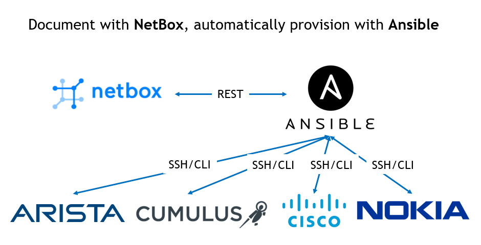
NetBox is a wonderful open source tool, which is “designed to help manage and document computer networks” according to their official web-site. The one sometimes calls it as data centre infrastructure and IP address management tool, though it can a bit more. From what I tested myself, and what I’m going to demonstrate to you in this article, NetBox is really can be a “source of truth” for your network (data centre, service provider or enterprise). It means it can provide you the desired state of the network, which can be automatically implemented to network functions over incredibly good APIs. Besides that, NetBox can really document everything you have in your network: locations, racks, PDU, ODF, connection to external providers and, for sure, network functions (switches, routers, firewalls, etc.) and endpoints (servers, desktops, etc.). These capabilities make NetBox useful tool for network planers and operations.
I strongly recommend you to read the official documentation of NetBox, where you can learn all the details explained in the easy way.
If you are following my blog, you might have read recently we talked about different data models, and the way the abstract data models are translated to the data model (YANG or CLI) of different network elements. In this article we’ll use the data modelling done inside NetBox as an abstract data model, which will be then translated into particular data model of the network elements.
What are we going to test?
To make it clearer, we are going to undertake the following steps using NetBox and Ansible:
- Install NetBox as a Docker containers on our management host.
- Document several data centre locations including IP addressing and Network functions modelling.
- Automatically provision network functions based on the information documented in NetBox.
Software version
The following software components are used in this lab.
Management host:
- CentOS 7.5.1804 with python 2.7.5
- Ansible 2.7.0
- Docker-CE 18.09
- Containerized NetBox
Service Provider Fabric:
- Nokia SR OS 16.0.R5 [guest VNF]
- Arista EOS 4.21.1.1F [guest VNF]
- Cisco IOS XR 6.5.1 [guest VNF]
- Cumulus Linux 3.7.3 [guest VNF]
More details about Service Provider Fabric you may find in the previous articles.
Topology
The general introduction of the Docker setup was done in the Service Provider Fabric setup, so we assume you have it installed. Nevertheless, you can find below the topology of the management network, what is used in Data Centre Fabric:
2
3
4
5
6
7
8
9
10
11
12
13
14
15
16
17
18
19
20
21
22
23
24
25
26
27
28
29
30
31
| |
| +-----------------+ +-----------------+ |
| | de+bln+spine+101| (c)karneliuk.com // Data Centre Fabric | de+bln+spine+201| |
| | (Cisco IOS XRv) | | (Nokia VSR) | /\/\/\/\/\ |
| | Lo0: .1 | | system: .2 | / \ |
| | BGP AS: 65000 | | BGP AS: 65000 | / Docker \ |
| +-------+---------+ IP^4: 192.168.141.0/25 +--------+--------+ \ / |
| | IPv6: fc00:de:1:ffff::/64 | +------------+ |
| | MgmtEth0/CPU0/0 | MgmtEth0/CPU0/0| Management | |
| | .25/:25 | .26/:26 | host | |
| | | +------+-----+ |
| | | | |
| | | | ens33 |
| +-------------------+--------------+---------------------------------+-------------+-------------------+---+ .137 |
| | | | | :137 |
| | | | | |
| | | | | |
| | eth0 | eth0 | Management1 | Management1|
| | .21/:21 | .22/:22 | .23/:23 | .24/:24 |
| | | | | |
| +------------------+ +---------+--------+ +---------+--------+ +---------+--------+ |
| | de-bln-leaf+111 | | de+bln+leaf-112 | | de+bln+leaf+211 | | de+bln+leaf+212 | |
| | (Cumulus VX) | | (Cumulus VX) | | (Arista vEOS) | | (Arista vEOS) | |
| | lo: .101 | | lo: .102 | | Lo0: .104 | | Lo0: .105 | |
| | BGP AS: 65101 | | BGP AS: 65102 | | BGP AS: 65104 | | BGP AS: 65105 | |
| +------------------+ +------------------+ +------------------+ +------------------+ |
| |
| |
| |
+--------------------------------------------------------------------------------------------------------------------------------+
You can use any hypervisor of your choice (KVM, VMWare Player/ESXI, etc) to run guest VNFs. For KVM you can use corresponding cheat sheet for VM creation.
Previously, when we were speaking about data centre networks, we had to use very small topology. Today we can extended it a bit more (even without considering the new home lab):
2
3
4
5
6
7
8
9
10
11
12
13
14
15
16
17
18
19
20
21
22
23
24
25
26
27
28
29
30
31
| |
| +-----------------+ +-----------------+ |
| | de-bln-spine-101| (c)karneliuk.com // Data Centre Fabric | de-bln-spine-201| |
| | (Cisco IOS XRv) | | (Nokia VSR) | |
| | Lo0: .1 | | system: .2 | |
| | BGP AS: 65000 | IPv4 links: 169.254.0.0/24 eq 31 | BGP AS: 65000 | |
| +--+---+---+---+--+ IPv6 loopb: 10.1.1.0/24 eq 32 +--+---+---+---+--+ |
| |.0 |.4 |.8 |.12 IPv6 links: fc00:de:1:0::/64 eq 127 |.2 |.6 |.10|.14 |
| +-----------------+:0 |:4 |:8 |:c IPv6 loopb: fc00:de:1:1::/64 eq 128 |:2 |:6 |:a |:e |
| | | | | | | | | |
| | +------------------------------------------------------------------------+ | | | |
| | | | | | | | | |
| | | +-----------+ +------------------------------------------+ | | |
| | | | | | | | | |
| | | +-----------------------------------------+ +------------+ +----------------+ |
| | | | | | | | | |
| | | +-----------------------------------------------------------------------+ | |
| | | | | | | | | |
| | swp3 | swp4 | swp3 | swp4 | Eth3 | Eth4 | Eth3 | Eth4 |
| | .1/:1| .3/:3 | .5/:5| .7/:7 | .9/:9| .11/:b |.13/:d| .15/:f |
| +-----+------+-----+ +-----+------+-----+ +-----+------+-----+ +-----+------+-----+ |
| | de-bln-leaf-111 +--------------+ de-bln-leaf-112 | | de-bln-leaf-211 +--------------+ de-bln-leaf-212 | |
| | (Cumulus VX) | swp1 swp1 | (Cumulus VX) | | (Arista vEOS) | Eth1 Eth1 | (Arista vEOS) | |
| | lo: .101 | | lo: .102 | | Lo0: .104 | | Lo0: .105 | |
| | BGP AS: 65101 +--------------+ BGP AS: 65102 | | BGP AS: 65104 +--------------+ BGP AS: 65105 | |
| +--+------------+--+ swp2 swp2 +--+------------+--+ +--+------------+--+ Eth2 Eth2 +--+------------+--+ |
| | | | | | | | | |
| + + Anycast IP: .100 + + + + Anycast IP: .103 + + |
| |
+--------------------------------------------------------------------------------------------------------------------------------+
In this topology we have 2 pairs of leaf switches (2x Cumulus VX, 2x Arista vEOS-lab) and 2x spine switches (1x Cisco IOS XR and 1x Nokia VSR). The only reason, why we have used such split is the resources (RAM, CPU) required by each network element.
Nokia SR OS perfectly serves any leaf role, such L2 VNI, L3 VNI asymmetrical or L3 VNI symmetrical.
The Data Centre Fabric is running eBGP in compliance with RFC7938, as we demonstrated several times before. There is a MC-LAG between Leafs in the pair for redundant connectivity of endpoints (servers). In this lab we are going to focus only on an underlying fabric setup without actual configuration of VTEPs and customer tenants, what we will describe in a separate article.
The topologies and initial configuration files you can find on my GitHub.
Multiple data centres topology
NetBox is used for documentation your network and IT infrastructure in general, and to show its power we’ll extend a bit the topology above in the following way:
- We will document the 4 data centres in 2 regions.
- Each data centre will have internally the same network topology as shown earlier. The only differences will be the hostnames of the network functions and used IP addresses
To make it more interesting, I will take as an example the real data centres, which provides collocation services. There is a nice web-site which, I have chosen to search for data centres :
| Region | City | Data Centre | Hostname prefix |
| DE | Berlin | e-shelter Berlin | de-bln |
| DE | Frankfurt am Main | Equinix FR5 | de-ffm |
| UK | London | TELEHOUSE London (Metro) | uk-ldn |
| UK | Manchester | Reynolds House | uk-mcr |
There is no any certain logic, how I was creating data centres, besides all of them come from different suppliers and are located in the corresponding towns.
Now we can take off.
Installing NetBox as Docker container (actually, set of containers)
It starts with… Installation of NetBox itself. There are several options, how you can do this. You can choose whatever you prefer more, but in this article I focus on the Docker realisation using the docker-compose proposed on the official page. Let’s get started by cloning it to our Linux host:
2
3
4
5
6
7
8
9
10
11
12
13
14
15
16
17
18
19
20
21
22
23
24
25
26
27
28
29
Cloning into 'netbox-docker'...
remote: Enumerating objects: 28, done.
remote: Counting objects: 100% (28/28), done.
remote: Compressing objects: 100% (15/15), done.
remote: Total 984 (delta 11), reused 24 (delta 10), pack-reused 956
Receiving objects: 100% (984/984), 313.69 KiB | 0 bytes/s, done.
Resolving deltas: 100% (545/545), done.
$ cd netbox-docker/
$ ls -l
total 76
-rwxrwxr-x. 1 aaa aaa 2125 Apr 5 21:26 build-all.sh
-rwxrwxr-x. 1 aaa aaa 941 Apr 5 21:26 build-branches.sh
-rwxrwxr-x. 1 aaa aaa 3149 Apr 5 21:26 build-latest.sh
-rwxrwxr-x. 1 aaa aaa 7453 Apr 5 21:26 build.sh
drwxrwxr-x. 2 aaa aaa 78 Apr 5 21:26 configuration
drwxrwxr-x. 2 aaa aaa 112 Apr 5 21:26 docker
-rw-rw-r--. 1 aaa aaa 1714 Apr 5 21:26 docker-compose.yml
-rw-rw-r--. 1 aaa aaa 1637 Apr 5 21:26 Dockerfile
-rw-rw-r--. 1 aaa aaa 292 Apr 5 21:26 Dockerfile.ldap
-rw-rw-r--. 1 aaa aaa 2470 Apr 5 21:26 DOCKER_HUB.md
drwxrwxr-x. 2 aaa aaa 61 Apr 5 21:26 env
drwxrwxr-x. 2 aaa aaa 57 Apr 5 21:26 hooks
drwxrwxr-x. 2 aaa aaa 254 Apr 5 21:26 initializers
-rw-rw-r--. 1 aaa aaa 10175 Apr 5 21:26 LICENSE
-rw-rw-r--. 1 aaa aaa 19656 Apr 5 21:26 README.md
drwxrwxr-x. 2 aaa aaa 32 Apr 5 21:26 reports
drwxrwxr-x. 2 aaa aaa 4096 Apr 5 21:26 startup_scripts
-rw-rw-r--. 1 aaa aaa 7 Apr 5 21:26 VERSION
Theoretically, you can create your own build within a single Docker container or using multiple. But having the build proposed by the official NetBox community increases chances it’s stable and fully operational.
Once the container is downloaded, we need to make sure that Docker is up and running:
2
3
4
5
6
7
8
9
10
11
12
13
14
15
16
17
18
19
20
21
22
● docker.service - Docker Application Container Engine
Loaded: loaded (/usr/lib/systemd/system/docker.service; disabled; vendor preset: disabled)
Active: active (running) since Fri 2019-04-05 21:11:42 CEST; 22min ago
Docs: https://docs.docker.com
Main PID: 13369 (dockerd)
Tasks: 17
Memory: 121.9M
CGroup: /system.slice/docker.service
└─13369 /usr/bin/dockerd -H fd:// --containerd=/run/containerd/containerd.sock
Apr 05 21:11:40 sand7.karneliuk.com dockerd[13369]: time="2019-04-05T21:11:40.254862377+02:00" level=info msg="pickfirstBalancer: HandleSubConnStat...ule=grpc
Apr 05 21:11:40 sand7.karneliuk.com dockerd[13369]: time="2019-04-05T21:11:40.274651657+02:00" level=info msg="[graphdriver] using prior storage dr...verlay2"
Apr 05 21:11:40 sand7.karneliuk.com dockerd[13369]: time="2019-04-05T21:11:40.527608927+02:00" level=info msg="Graph migration to content-addressab...seconds"
Apr 05 21:11:40 sand7.karneliuk.com dockerd[13369]: time="2019-04-05T21:11:40.529298501+02:00" level=info msg="Loading containers: start."
Apr 05 21:11:42 sand7.karneliuk.com dockerd[13369]: time="2019-04-05T21:11:42.114206478+02:00" level=info msg="Default bridge (docker0) is assigned...address"
Apr 05 21:11:42 sand7.karneliuk.com dockerd[13369]: time="2019-04-05T21:11:42.325780326+02:00" level=info msg="Loading containers: done."
Apr 05 21:11:42 sand7.karneliuk.com dockerd[13369]: time="2019-04-05T21:11:42.449881797+02:00" level=info msg="Docker daemon" commit=d14af54 graphd...=18.09.4
Apr 05 21:11:42 sand7.karneliuk.com dockerd[13369]: time="2019-04-05T21:11:42.450301836+02:00" level=info msg="Daemon has completed initialization"
Apr 05 21:11:42 sand7.karneliuk.com dockerd[13369]: time="2019-04-05T21:11:42.468438664+02:00" level=info msg="API listen on /var/run/docker.sock"
Apr 05 21:11:42 sand7.karneliuk.com systemd[1]: Started Docker Application Container Engine.
Hint: Some lines were ellipsized, use -l to show in full.
After this is done we can compose the service:
2
3
4
5
6
7
8
9
10
11
12
13
14
15
16
17
18
19
20
21
22
23
24
25
26
27
28
29
30
31
32
33
34
35
36
37
38
39
40
41
42
43
44
45
46
47
Pulling postgres (postgres:10.4-alpine)...
10.4-alpine: Pulling from library/postgres
Digest: sha256:b00851e5a07b910a18f9211cec807a1256cec38bbf7aa06859aba79acf79b3a8
Status: Image is up to date for postgres:10.4-alpine
Pulling redis (redis:4-alpine)...
4-alpine: Pulling from library/redis
8e402f1a9c57: Pull complete
4c2113a1bbc9: Pull complete
a4b5ad98d179: Pull complete
41457a7cc0c5: Pull complete
f987c6e1a2b3: Pull complete
2a3ef38f1fd4: Pull complete
Digest: sha256:7a543f606ea3e055a18ccbda719fb1e04f6922078f733cb39863619983e05031
Status: Downloaded newer image for redis:4-alpine
Pulling netbox-worker (netboxcommunity/netbox:latest)...
latest: Pulling from netboxcommunity/netbox
8e402f1a9c57: Already exists
cda9ba2397ef: Pull complete
7a817918d4d5: Pull complete
e64fbda5eefb: Pull complete
6d027cc21c42: Pull complete
3dfb562dd2d1: Pull complete
623832c4d3eb: Pull complete
b5f7934d7258: Pull complete
2c745deeff8a: Pull complete
9bcf52b9b91a: Pull complete
f3f35c63de7d: Pull complete
84b3efd2582a: Pull complete
f3012ae1292d: Pull complete
3cce5ffe42b7: Pull complete
707d4b943f02: Pull complete
3e4add78e15a: Pull complete
Digest: sha256:60195d281727d50770731b84f0a2b7c627d41ee10f4945aa6352efbb156d4b9c
Status: Downloaded newer image for netboxcommunity/netbox:latest
Pulling netbox (netboxcommunity/netbox:latest)...
latest: Pulling from netboxcommunity/netbox
Digest: sha256:60195d281727d50770731b84f0a2b7c627d41ee10f4945aa6352efbb156d4b9c
Status: Image is up to date for netboxcommunity/netbox:latest
Pulling nginx (nginx:1.15-alpine)...
1.15-alpine: Pulling from library/nginx
8e402f1a9c57: Already exists
56b0d9b69cc9: Pull complete
b66c8bb200cc: Pull complete
4ec77fc9c55f: Pull complete
Digest: sha256:d5e177fed5e4f264e55b19b84bdc494078a06775612a4f60963f296756ea83aa
Status: Downloaded newer image for nginx:1.15-alpine
This process creates downloads the proper images from the Docker hub registry. The following images are acquired:
2
3
4
5
6
REPOSITORY TAG IMAGE ID CREATED SIZE
netboxcommunity/netbox latest 21dbb3691c58 16 hours ago 529MB
nginx 1.15-alpine 0476319fbdad 9 days ago 20MB
redis 4-alpine adbfeec2927e 2 weeks ago 36.2MB
postgres 10.4-alpine 962ed899c609 8 months ago 72.9MB
The first image “netboxcommunity/netbox” contains the code of the NetBox application itself. But the application requires several another supporting application, therefore the container with “postgres” database, “nginx” webserver and “redis” database are pulled as well. The next, and final, step in the building NetBox app is to build the application itself out of the images, meaning to run containers with the proper configuration. You don’t need to worry about the configuration, as it’s already prepared, so you need only to launch it:
2
3
4
5
6
7
8
9
10
11
12
Creating volume "netboxdocker_netbox-redis-data" with local driver
Creating volume "netboxdocker_netbox-media-files" with local driver
Creating volume "netboxdocker_netbox-report-files" with local driver
Creating netboxdocker_postgres_1 ... done
Creating netboxdocker_redis_1 ... done
Creating volume "netboxdocker_netbox-postgres-data" with local driver
Creating netboxdocker_netbox-worker_1 ... done
Creating netboxdocker_postgres_1 ...
Creating netboxdocker_netbox_1 ... done
Creating netboxdocker_netbox_1 ...
Creating netboxdocker_nginx_1 ... done
In the snippet above, the persistent data storages for Docker containers are created to store configuration data even upon container restart, following by launch of the containers. In total there five containers launched, which you can verify as follows allow:
2
3
4
5
6
7
CONTAINER ID IMAGE COMMAND CREATED STATUS PORTS NAMES
32cc947ec3d3 nginx:1.15-alpine "nginx -c /etc/netbo…" About a minute ago Up About a minute 80/tcp, 0.0.0.0:32769->8080/tcp netboxdocker_nginx_1
1e8885a71190 netboxcommunity/netbox:latest "/opt/netbox/docker-…" About a minute ago Up About a minute netboxdocker_netbox_1
d43ef0cd565b netboxcommunity/netbox:latest "python3 /opt/netbox…" About a minute ago Up About a minute netboxdocker_netbox-worker_1
bdc68612f29d postgres:10.4-alpine "docker-entrypoint.s…" 2 minutes ago Up About a minute 5432/tcp netboxdocker_postgres_1
5d815c016171 redis:4-alpine "docker-entrypoint.s…" 2 minutes ago Up About a minute 6379/tcp netboxdocker_redis_1
All the containers are up and running, so you need just to understand, what is the front-end where you need to connect to. The front-end is the NGINX http server, and there is information that its port 8080 is exported out of the Docker network “0.0.0.0:32768->8080/tcp”. Let’s connect to NAT’ed port:

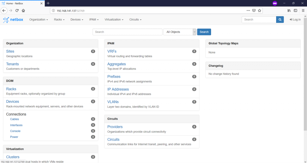
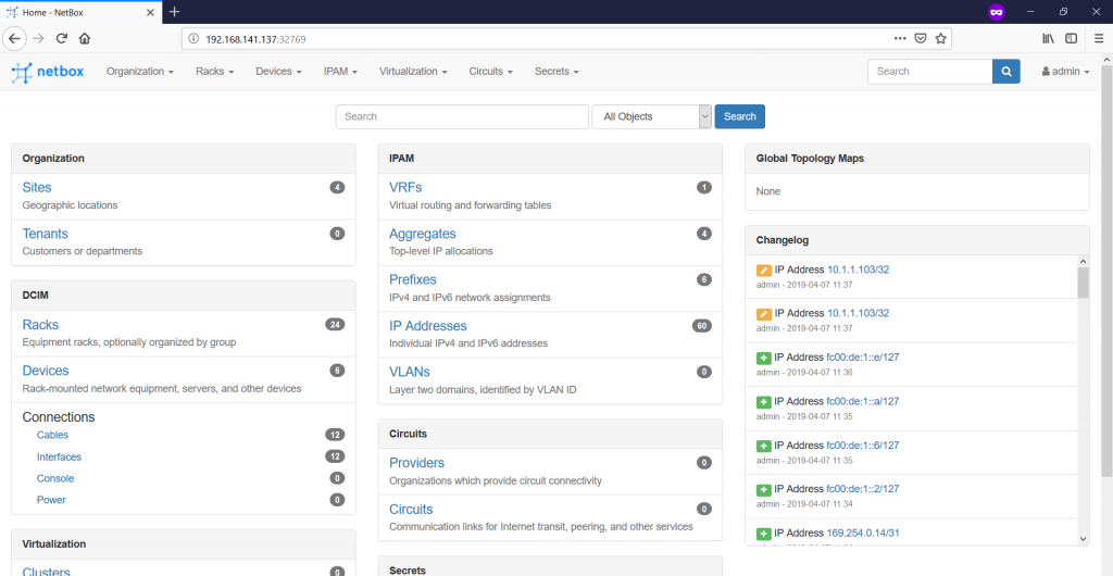
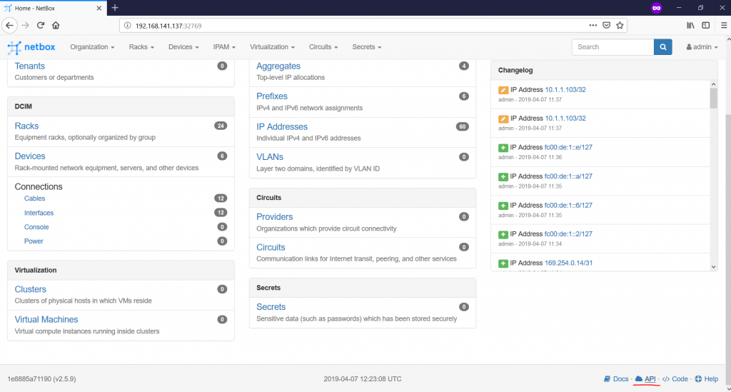
Here is the freshly built and started NetBox. As you see it runs on the port “32768” of the VM with the Docker, where “192.168.141.137” is the IP address of this VM. There is nothing documented yet, that’s why you see “0” values everywhere. Now we can proceed with the usage of NetBox.
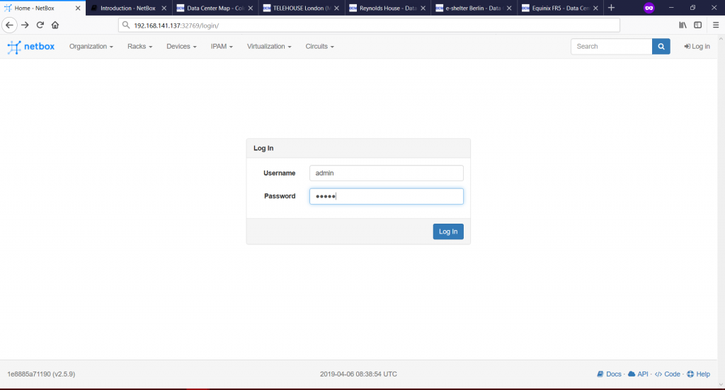
And the first step is to login using default credentials “admin/admin”:

Documenting network in NetBox
NetBox has very clear documentation. Frankly speaking, myself I’ve used so far only this resource to prepare this article and create automation with Ansible. Generally NetBox provides you possibility to document physical and virtual infrastructure. We will focus on the network part and physical infrastructure, such as:
- Physical locations (data centres, rooms within datacentres, racks, place of the network functions inside racks).
- Network devices themselves (HW/SW versions, ports, mapping of MAC/IP addresses per ports).
- IP Addresses (aggregated ranges, detailed prefixes and host IP addresses).
- Connections (physical connectivity between network devices).
As said, this is just the small part of the information NetBox can document. For the full information, refer to the official documentation.
Some other documentation capabilities, such as VLANs, VRFs, Servers and VMs will be described later in the articles, where we will use NetBox for modelling of the services.
#1. Physical locations
Let’s start with the documentation of the physical locations. There is a certain hierarchy exists inside NetBox. The starting points is to define the regions, where our data centres are located.
In the beginning of the article we have provided, what are the regions, where we have data centres, so let’s configure them. To do that we navigate to “Organization -> Regions -> + ” in the top menu:

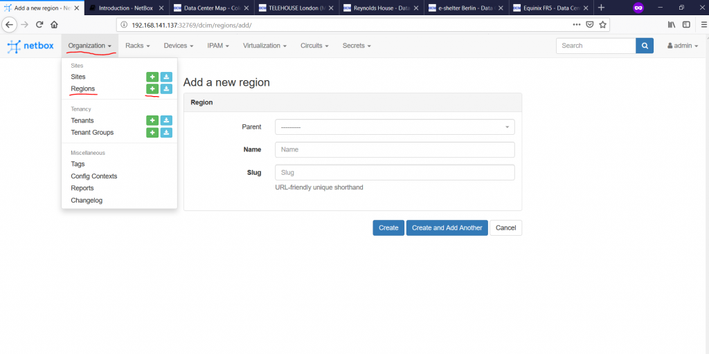
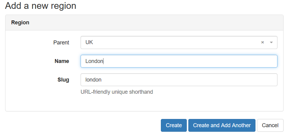
Once you press the “+”, you are asked to create new region. There is a possibility to create hierarchy of regions, like one parent region host several children regions. We’ll use country as parent region, whereas city will be children:

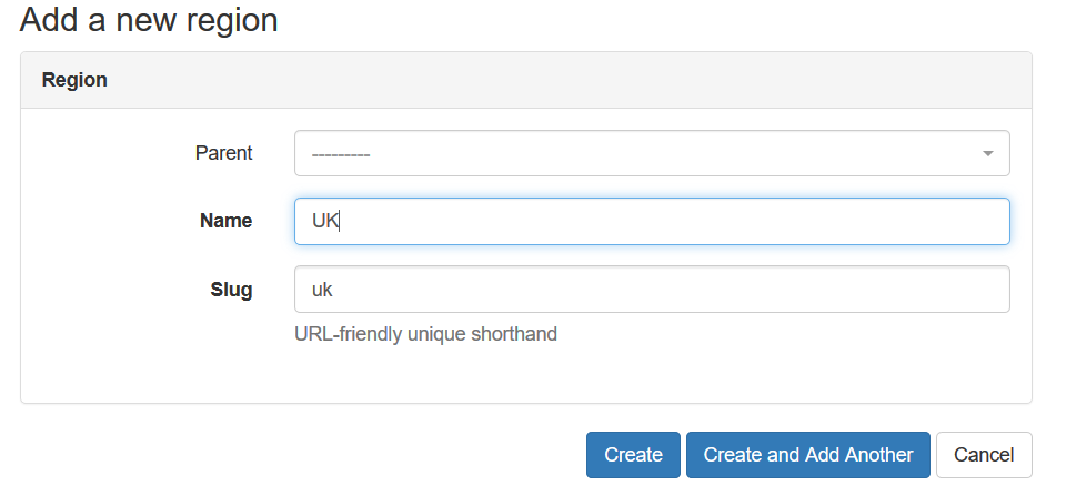
To make any region depending on the parent, you just need to set “Parent” filed to the proper value:

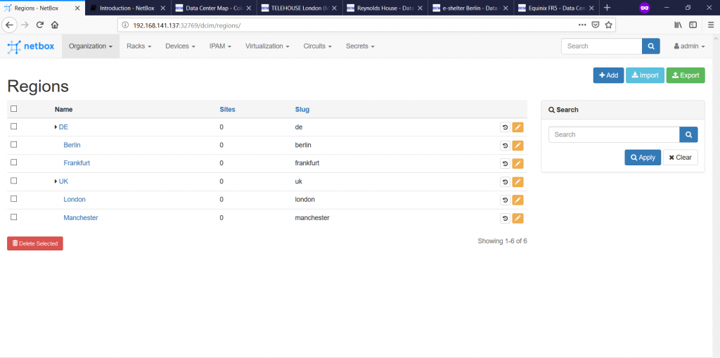
Once we’ve created all the regions, we see their hierarchy:

The next step is to document the data centres themselves. To do that, we go to “Organization -> Sites à -> ” tab:

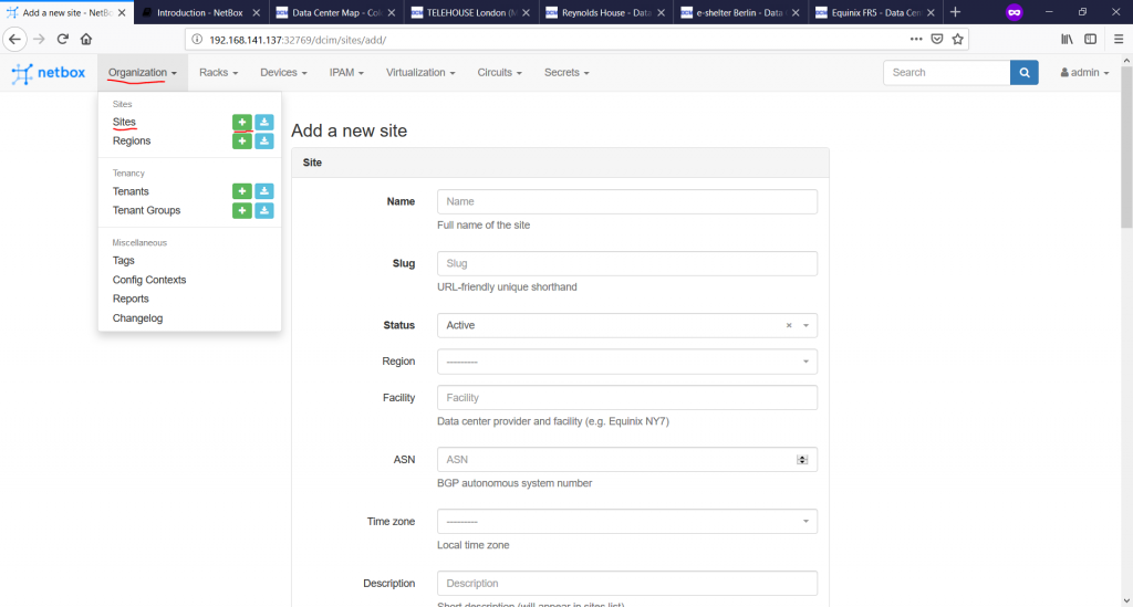
here are only three mandatory fields, you need to fill in: “Name”, “Slug” and “Status”:
- “Name” describes the data centre within your network design, so it’s kind of arbitrary name.
- “Slug” is a very good construct. You have seen it earlier in Region as well, and it exists for ANY entry in NetBox. What it does, it translates any name in http-like URL to make the interaction over REST API easier.
- “Status” helps to understand to the team, what are status of the data centre. There are 3 options possible: Planned (not yet in production, Active (in production), Retired (not more in production.
Remember, NetBox is a documentation tool, so any information is for people, not for devices. On the other hand, this information can be exposed over REST API, other applications can use it if programmed so.
Besides mandatory parameters, there are plenty of optional ones, which are very useful. Take a look on the screenshot below:

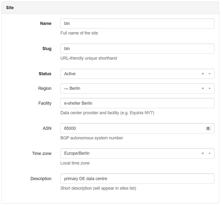
We have provided the name of the data centre according to the hostname prefix provided in the beginning, and filled in all the parameters within this tab. There are a couple of more groups of parameters not shown on the screenshot above “Tenancy”, “Contact Info”, “Tags”, “Comment”:
- “Tenancy” generally shows the belonging of some resources entirely to some entity, like customer or department. If the resource is shared between different tenants, normally this value isn’t set.
- “Contact Info” allows to store the parameters, such as physical/shipping address, phone numbers, GPS and so on.
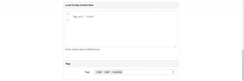
- “Tags” allows you to add certain tags, which can be used for filtering the information in search output, like “Germany”, “production”, “staging”, “new site” and so on, based on any your logic.
- “Comment” provides possibility to add any free-text information, which you feel is necessary, but wasn’t explicitly filled in any field above.
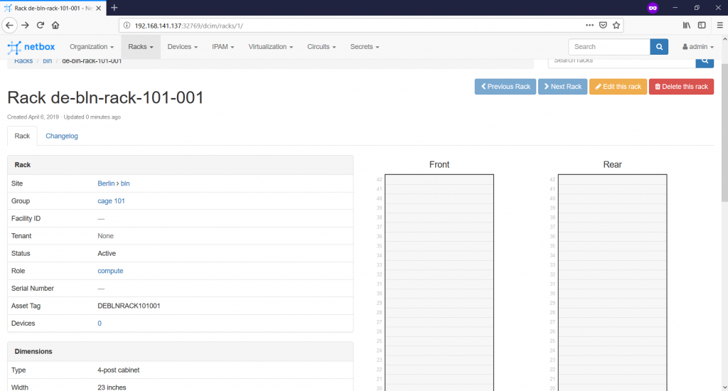
Once you document all the information you need and press “Create” button, you get to the general pane showing your data centre:
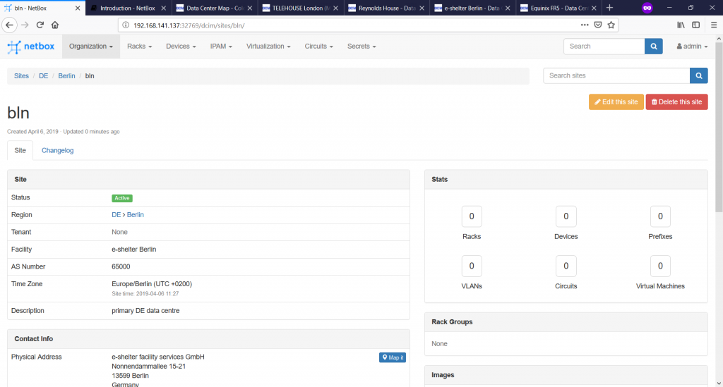
As we don’t have any further resources created, we have “0” values within “Stats”.
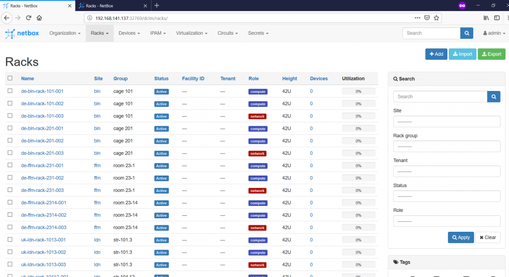
Once we create all the data centres and go to the “Organization -> Sites” tab, we will see all of them:

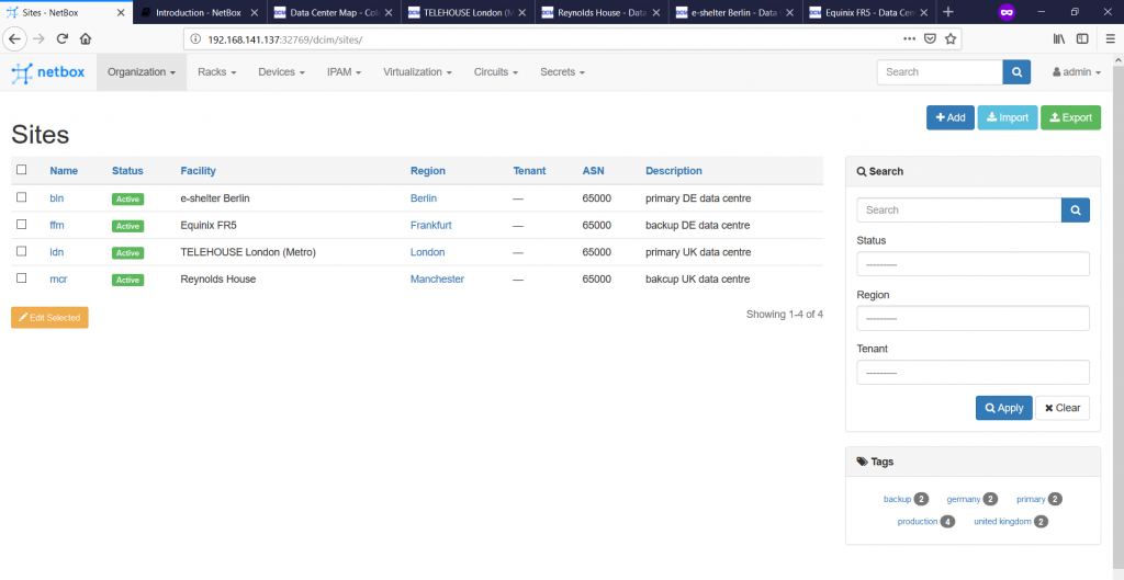
On the right side of the browser, you see the search pane, which besides possibility to look for a certain data centre, gives you option to limit the list, so that data centres from a certain region, of a certain status or with a certain tag are shown.
It’s quite convenient that you see also the BGP ASN, which this data centre belongs to. As we are using the eBGP fabric according to RFC 7938, this BGP ASN represents the ASN, which our infrastructure use to connect to any Service Provider network for DCI.
So far we have documented the Regions, where our data centres are located, and Sites (the data centres themselves). The next step is to defines the cages within the data centres called Rack Groups and Racks themselves in accordance with Rack Roles.
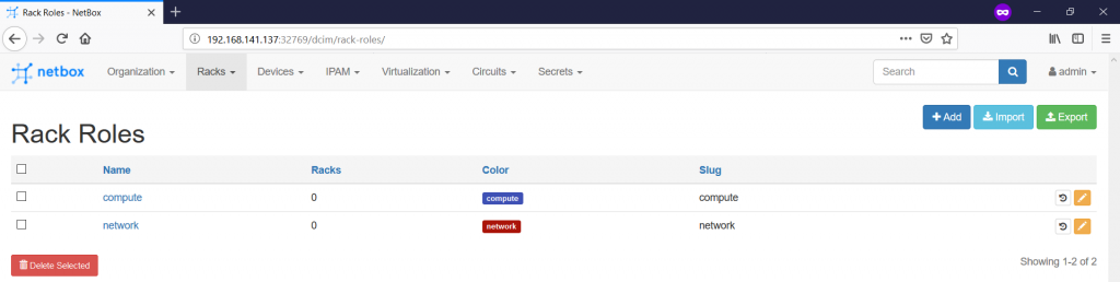
Let’s proceed further with the Rack Roles. Actually, it’s just an attribute helping you to identify the main purpose of the rack within the data centre. To create it this role, follow to the “Racks -> Rack Roles -> +” tab:

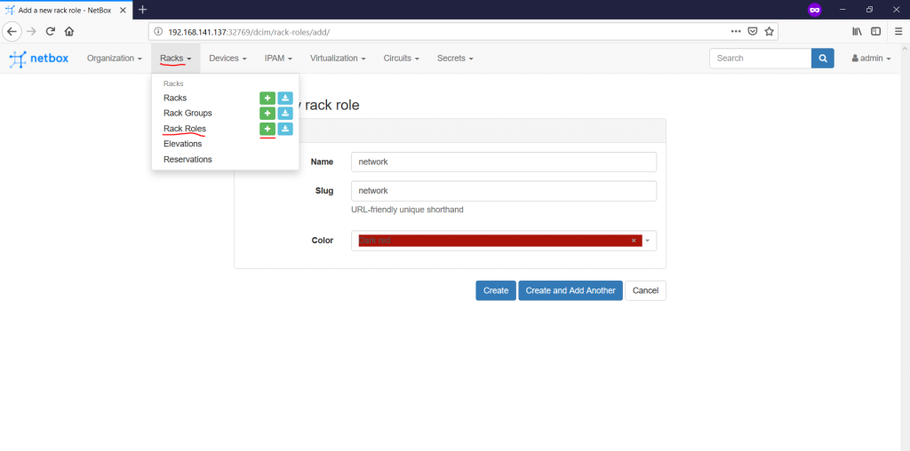
For this article, we’ll create two rack roles: “network” and “compute”. The first one will host pure network equipment (spines, borders, firewalls, etc), whereas the second one will host leafs and servers. You also associates here any colour code you like with the certain rack type to visually diverse the racks. Here are our created roles:

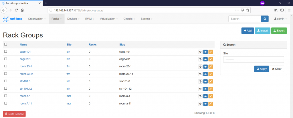
The next step is to add the Rack Groups on the “Racks -> Rack Groups -> +” pane:

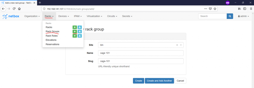
The Rack Group how is it coming from the name is kind of set of the racks within the certain location, or within the certain role. For instance, it might a wiring closet on the floor in the campus or a room/cage within the data centre, that’s why it’s mandatory to provide reference, which site hosts this rack group. From the prospective of this article, we will create two cages in each data centre we have. The name is absolutely arbitrary value, like you can follow the naming from the data centre location or create your own logic:

Finally we reach the point, where we need to define the racks themselves on the “Racks -> Racks -> +” tab:

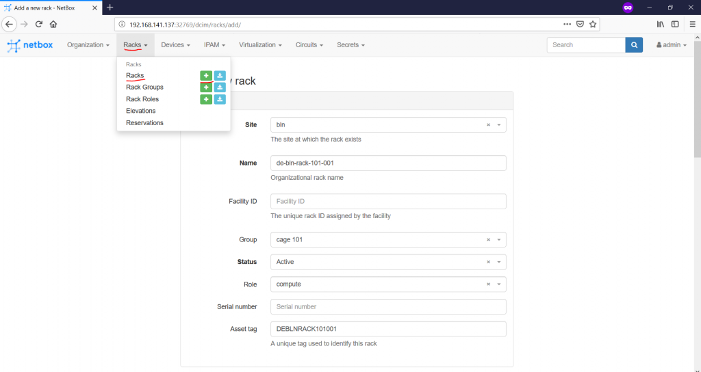

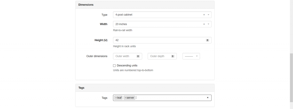
The mandatory fields are site, name, status and width/height. All of them are self-explanatory. The interesting thing is that the rack group isn’t a mandatory parameters, so you could have omitted it. On the other hand, putting the group and the role are a good practice. There are also fields, such as serial number or asset tag, which might help you to identify the rack if you doing on-site activities. The category “Dimensions” is very important, as it provides parameters of the rack, such as type (frame, cabinet and wall-mount cabinet), width (inches) and height (RU – Rack Units). Once you create the rack, you get into its content:

You can add the devices here to the appropriate slot, but it also possible to add upon the device creation itself. So, let’s create 3 racks in each room in each data centre we have:

#2. Network functions
The next major step would the documentation of the network functions themselves. In the beginning of the article we’ve created shared which VNFs we are using, as the Data Centre Fabric is a fully virtual setup. To document the physical infrastructure, so we’ll emulate the physical network functions in the following way:
| VNF | PNF – HW | PNF – SW |
| Cumulus VX | Dell S5048F-ON | Cumulus Linux 3.7.4 |
| Arista vEOS-lab | Arista 7060SX2-48YC6 | Arista EOS 4.21.1.1F |
| Cisco XRv | Cisco NCS 5502 | Cisco IOS XR 6.5.2 |
The PNF is chosen based on the function they need to perform, that’s why you can have your own mapping.
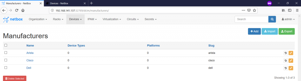
The first tab you need to fill in is the list of the manufacturers on the “Devices -> Manufacturers -> +” tab:

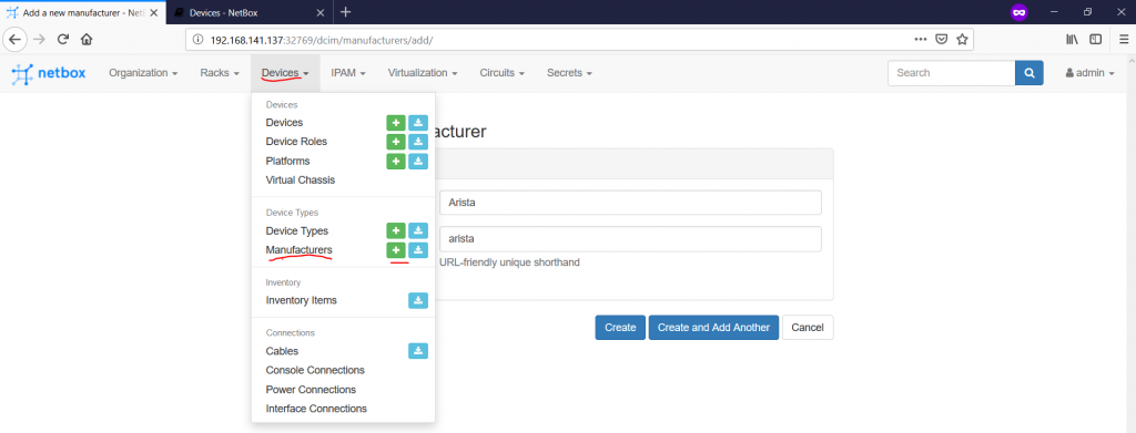
As you can see, there are not too many things to fill in, so you can accomplish this part relatively quickly:

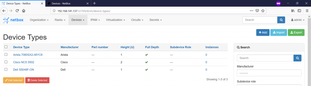
After you have defined all your manufactures, you can create the device types or devices models navigating to the “Devices -> Device Types -> +” pane:

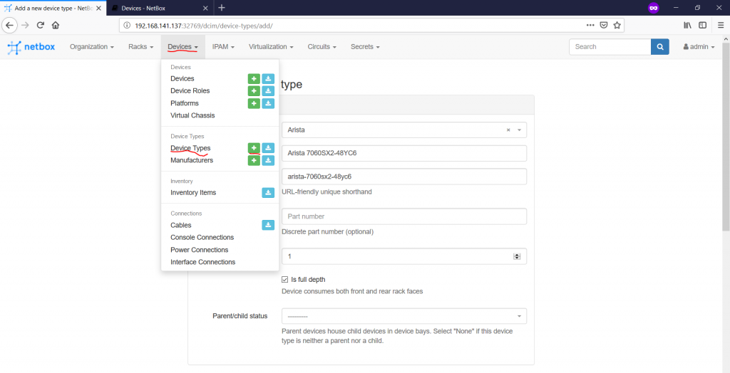
Basically, we define here only the device name, its height in RU and parent/child behaviour (applicable only to server chassis). Following the VNF to PNF mapping we’ve just provided, we create three device types:

Going further, we can create the platform at “Devices -> Platforms -> +” tab:

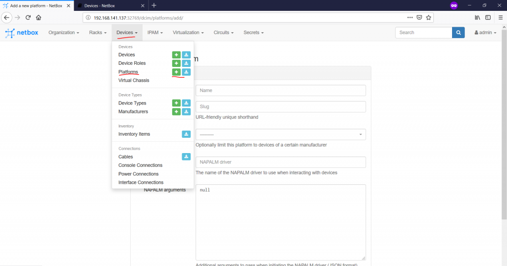
This part is not mandatory, but is quite useful, if you are familiar with NAPALM drivers for your network elements. I’m not, so I will skip this part for now and will go the next one.
The next one is the device roles, where we define generic classes, where the devices belong to. These categories are created under the “Devices -> Device Roles -> +” context:

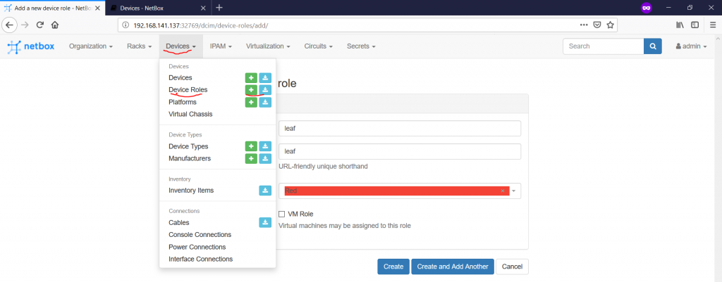
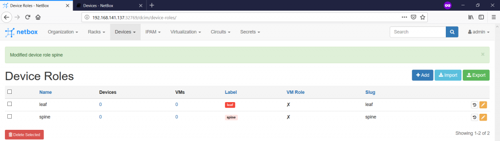
For our goal, we will create two categories called leaf and spine:

The final point for this part is add the real physical network functions as they are installed in the racks in the data centres. This is done on the “Devices -> Devices -> +” tab:

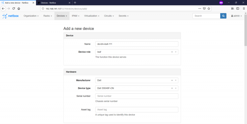


As you see, here we need to add plenty of information:
- In the “Device” category, we provide the name of the device together with its role.
- The following “Hardware” part defines the device type and the manufacturer the platform comes from.
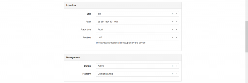
- The “Location” category defines the physical placement of the device that is the site, the rack and the position within the rack.
- The “Management” category defines the status of the device as well as the platform (hence, potential mapping to NAPALM drivers).
- The final part we configure (besides “Tags”) is “Local Config Context Data”, what provides to add any parameters we like, which will be associated with this device. We add here the “bgp_asn” variable to put the BGP ASN value according to the topology shown in the beginning of the article.
There are plenty of other categories, which I have skipped, as they aren’t used in this article.
In such a way we create all our network functions and assign them to racks:

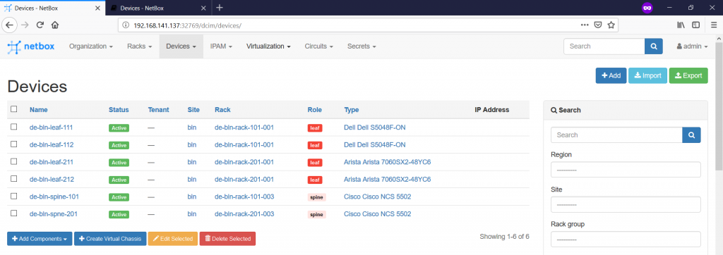
The network elements are created only for a single data centre in accordance with the topology provided in the very beginning.
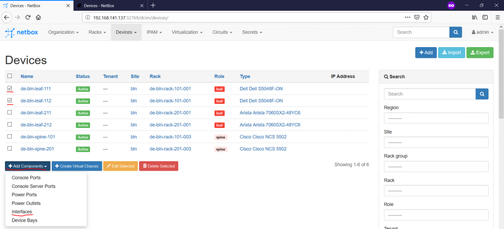
During the creation of the devices, we haven’t provided any information of the number of the ports, naming conventions used for them, power sockets and so on. This is the next step we need to do. We’ll focus only on the network ports (data plane and OOB) to show you how it’s working.
To add anything to the device, you need to tick the box in front of it and press “Add Components” button following by the respective category (“Interfaces” in our case):

Once you chose it, you get into specific configuration context, where you need to finalize your actions:

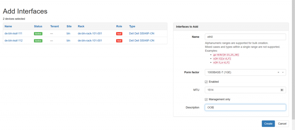
In such a way you create all the physical and logical interfaces you need to be associated with the device. For instance, the LAG (Form Factor – LAG) and loopback (Form Factor – virtual) interfaces are also created from this context.
Once you have added everything you need, you just click on the device name on the “Devices -> Devices” pane:

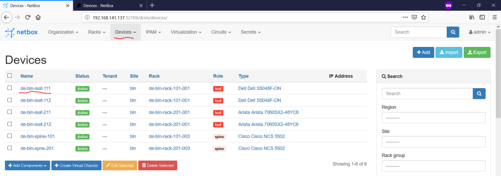
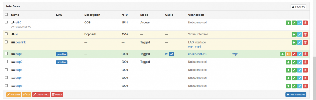
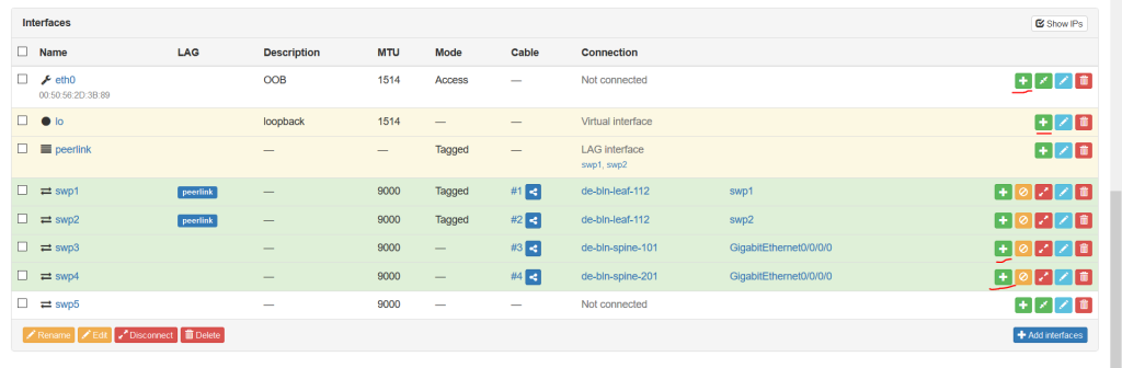
You see a lot of parameters you have configure earlier, but you need to scroll down till the ports to see them:


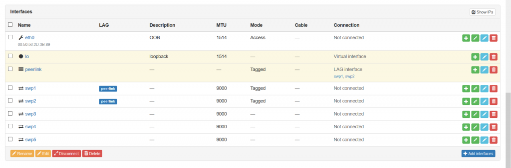
So we have added the interfaces existing in our VNFs according to the initial topology. We have also added the LAG called peerlink, which is typically exists between leaf pairs. To add intefaces there, you need to choose the physical interface you want to add and press the blue pen icon on the right side. Then you come into the configuration context of the interface:

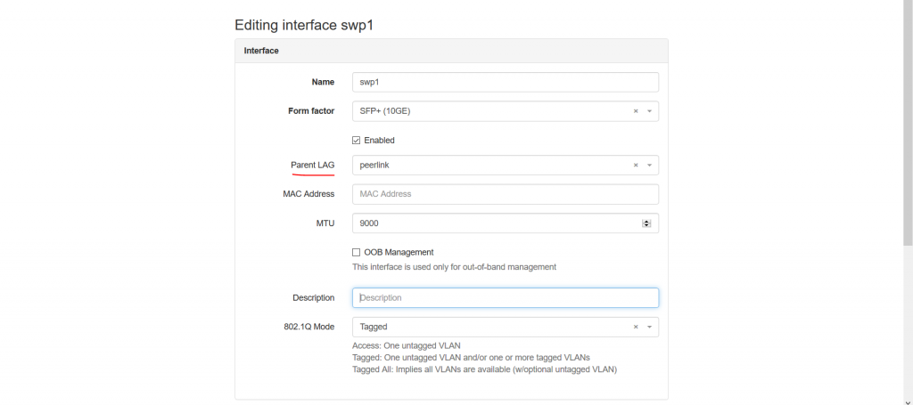
You can document here several parameters including the “Parent LAG” to signal the participation of the link in the certain LAG. Once this is done, you will see that the structure of the interfaces is updated:

In this manner, we create the ports for all the network functions we have. Once this is done, we can go to the next point, which is the documentation of the connectivity between the network functions.
#3. Connectivity
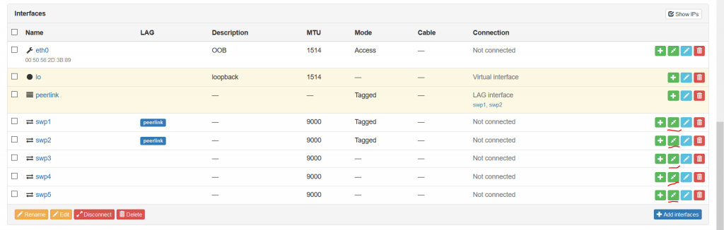
Our network functions are positioned inside the racks, but they are not-connected islands now. Therefore, as we said above, the next step is to connect them. Assuming you stay within the previous context, where you see the interfaces of the router, you need to push the green button with two arrows heading to each other:

Once you press that button, you are forwarded to the tab, where you need to define the “B”-side of the connectivity given that your chosen port is “A”-side:
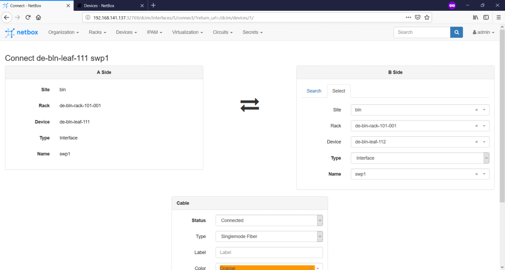
You have possibility to add also type of the cable, its colour for the documentation, attached label and the length. When you provide all the required information, you will see that the interface within the device context is connected now:

You need to repeat this step several times until you document all your wiring within the data centres, campuses and so on.
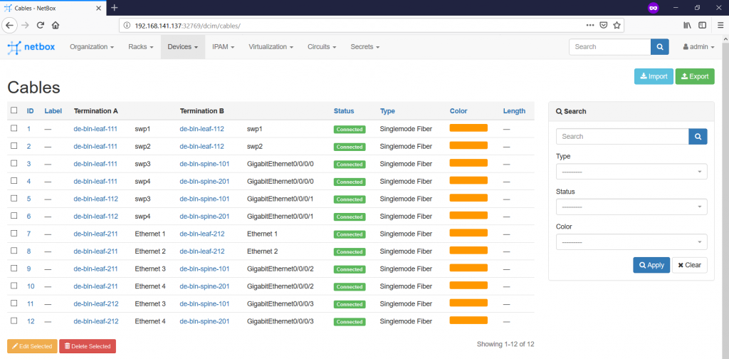
After you all the wirings are documented, you can check the status on the “Devices -> Cables” tab.

So far, the documentation of the physical infrastructure is finalized and we can go further with the documentation of the IP addresses.
#4. IP Addresses
The documentation of the IP addresses is performed within “IPAM” context. There are a lot of things, which you can defined there, but for this article we’ll configure just several of them.
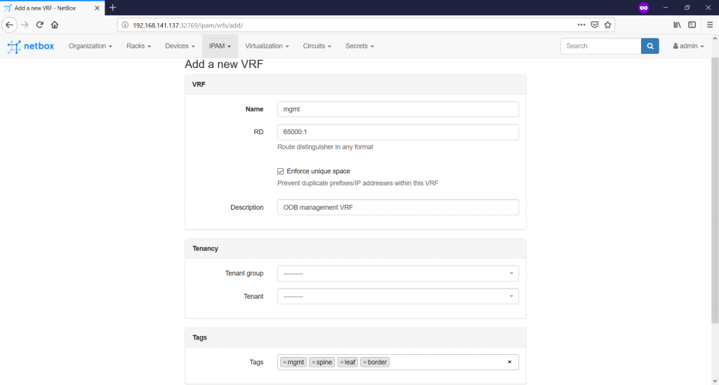
Let’s start with the VRF at the “IPAM -> VRFs -> +” tab. In future, we will use it for the documentation of the customer services, but now we’ll create just management VRF for OOB management:
This VRF will be used later, when we will be defining particular prefixes. But before we start with any particular prefix, we need to defined “RIRs” and so called “Aggregates”.
First of all, we need to create some RIRs. The logic is so that all the IP addresses (even private) must have a RIR. To create them, you should navigate to the “IPAM -> RIRs -> +” tab:

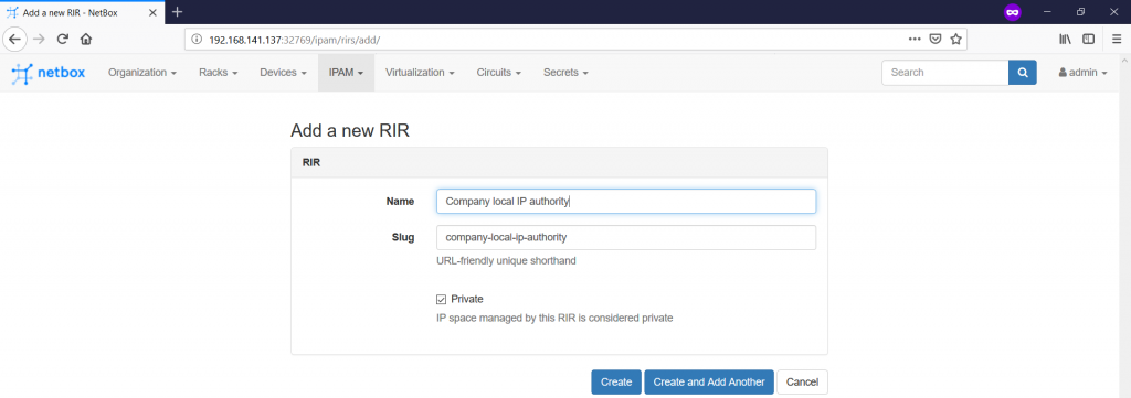
Though there is not too much information you can add, but it’s always important to track the origins of the IP addresses. Don’t forget to tick the “Private” box.
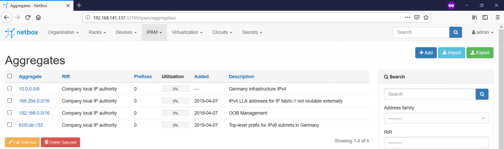
Second, you can now create the Aggregates on the “IPAM -> Aggregates -> +” pane:

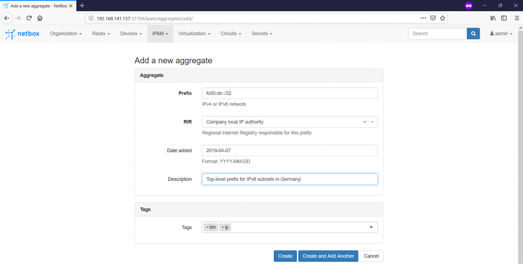
The main idea is that you define here some high level prefixes, which you can split further in smaller prefixes. From the prospective of your lab, we define the following Aggregates:

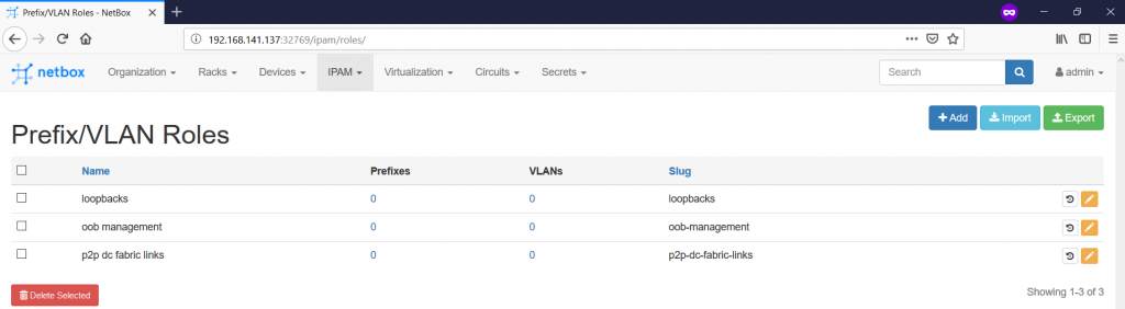
We have already ,let’s say, 50% of the input parameters for definition of the prefixes. We need to define 50% more, what is the Prefix/VLAN Roles. To do that, you need to navigate to the “IPAM -> Prefix/VLAN Roles -> +” tab:

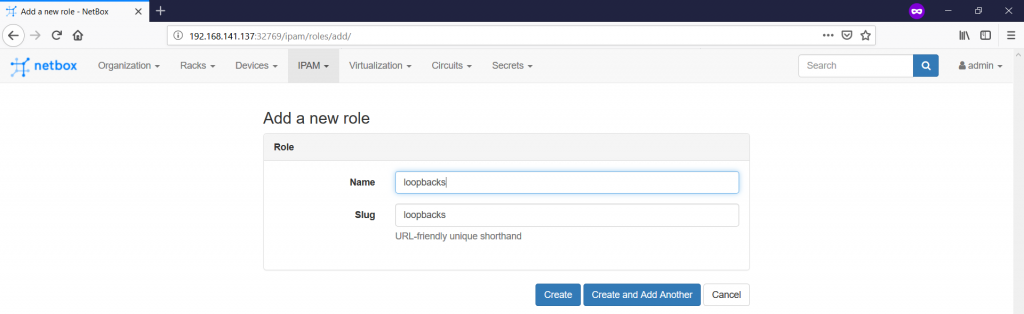
For the purpose of this article, we define three roles as show below:

So far, all the preparatory tasks for the definition of the prefixes are accomplished and we can proceed with the prefixes themselves on the “IPAM -> Prefixes -> +” tab:
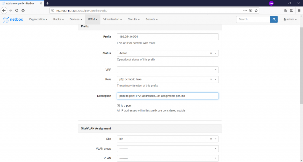
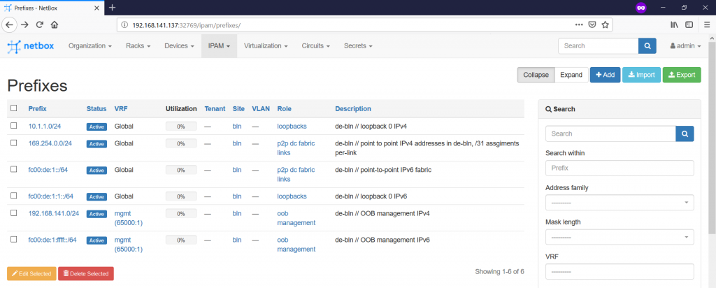
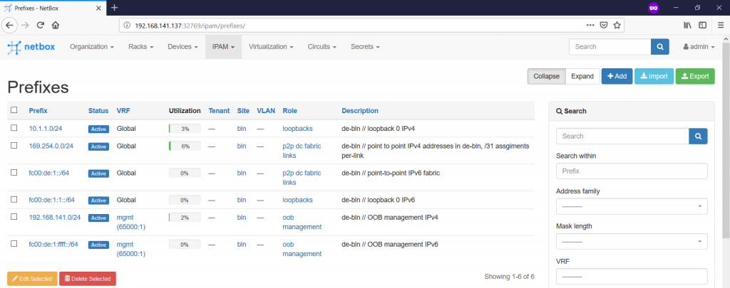
Generally, in the “prefix” tab you define the prefix value you expect to see in the routing table of the network elements or, at least, you plan to aggregate somewhere. There is also possibility to add VRF (if not specified, than global routing table is used), prefix role and so on. For this article we define six prefixes:
The very last point we need from the documentation scope of this article is to define the IP addresses, which are assigned to the interfaces. There are at least two possibilities, how we can do it:
- Create IP address on the “IPAM -> IP Addresses” tab and then assign them to the created devices on the “Devices -> Devices” tab.
- Create IP addresses directly from the “Devices -> Devices” context.
We’ll cover the second option. That’s why you should navigate to the “Devices -> Devices” tab and enter in the definition of the device. Scroll down to the list of the interfaces and push the green button with white plus to add IP address:

When you push this button, you get into the context of adding IP addresses:

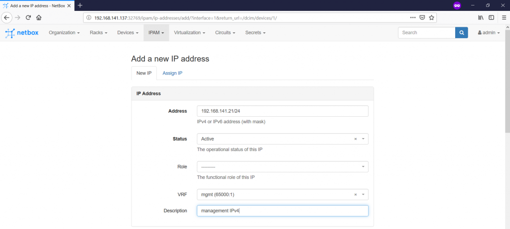
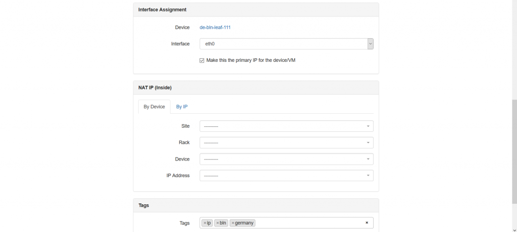
Here you create an IP address itself, provides related VRF, role and define its relation to the device/interface. Actually, the role is very useful attribute, as it helps to add specific roles, such as loopback, VIP, Anycast and so on. This role is heavily used in the Ansible integration, which you will find in the end of this article. You see also tick-box “Make this the primary IP for the device/VM”. I choose it for OOB management IP, but you can follow any logic you have. The IP address that is marked with this tick-box is automatically added to the “Management” section:

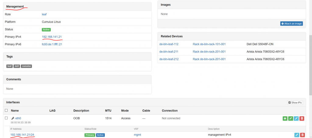
Also it’s worth to point out that for definition of IPv4 and IPv6 addresses the same form is used, what is quite convenient. NetBox itself understand what type of IP address it deals with.
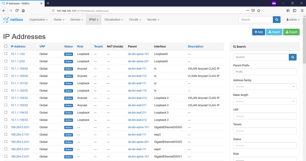
In such a manner we document all the IP addresses according to the topology of the Data Centre Fabric we shared in the very beginning. The following picture illustrates the fully documented IP addresses for a single device:
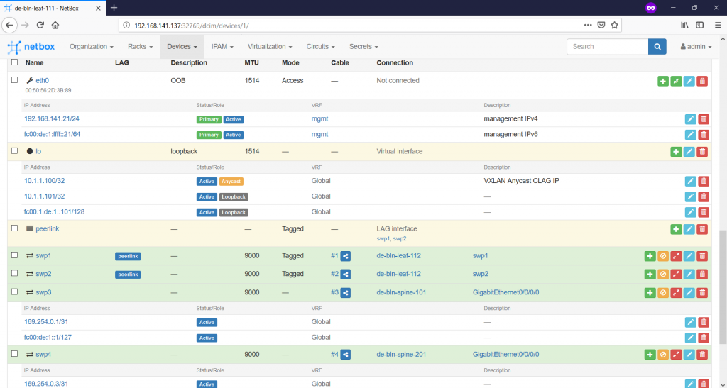
Once this task is accomplished, you can see the overall list of the IP addresses on the “IPAM -> IP Addresses” tab:

If you jump to the “IPAM -> Prefixes” tab, you can see that some of the prefixes we’ve defined show some utilization:

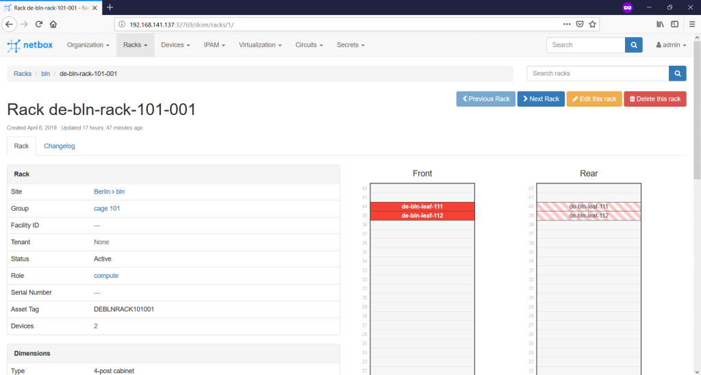
Finally, we are ready with the documentation of our small infrastructure. We can see now the rack with the switches looks like:

And the general information about our stats:

Exploring NetBox REST API
As we have said in the beginning, besides the possibility to easily document your entire network and IT infrastructure, NetBox has an outstanding REST API. Actually, all the CRUD (Create, Read, Update, and Delete) operations are available over REST API:
- POST request is used for Create.
- GET request is used for Read.
- PATCH and PUT requests are used for Update.
- DELETE request is sued for Delete.
These capabilities allow you to get data from the NetBox database for any automation activates, as well as update it in case of automation activities.
What is also very good is that the whole REST API documentation is built in NetBox itself. In order to access it, you just need to scroll to the bottom of the page and press “API” button:
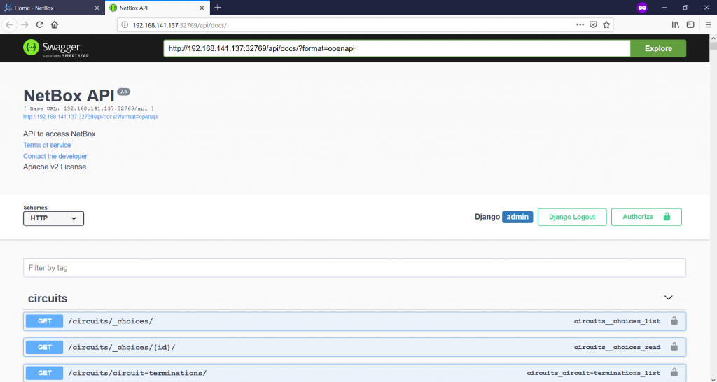
Once you click the link, you are forwarded to the new page, where you see all the paths together with the supported request types:

Here you can scroll across all the paths, the good thing is that their names are self-explanatory. For the subsequent integration with Ansible, I was looking for the paths, which contains the information about devices. I found it in “DCIM” part as “/dcim/devices”:

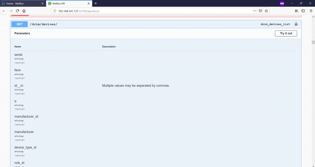
All the possible values, which may exist in the response to the GET response, you can find here. As you can see in the top right corner, there is a “Try it out” button, which provides you possibility to test the request immediately:
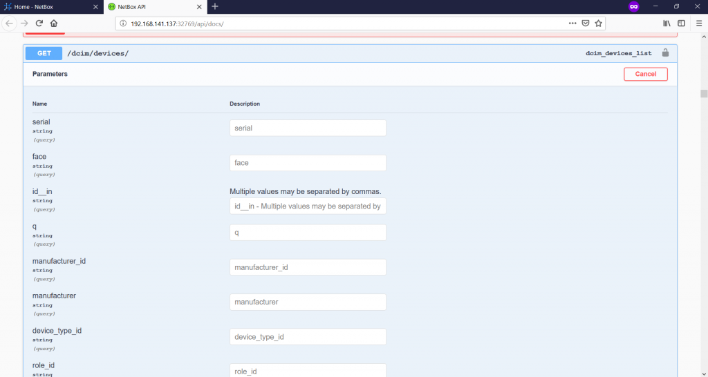
Once you push that button, you can provide any value to perform specific query and narrow down the possible response. But you can it left and just scroll down and press the “Execute button”:
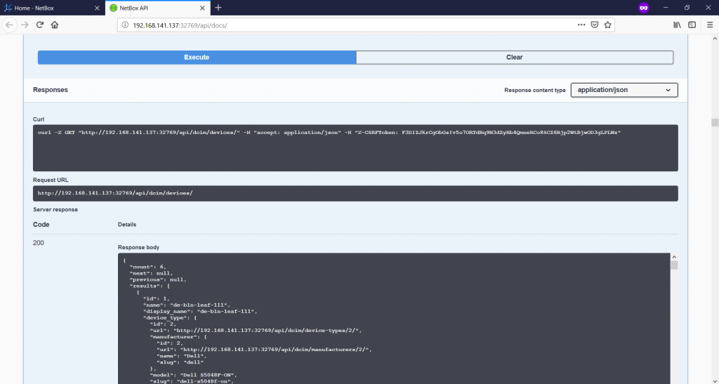
You see a lot of useful information after you press the “Execute” button:
- You see how you can get this information using curl from your Linux host.
- You see which URL was used.
- You see the content of the response itself.
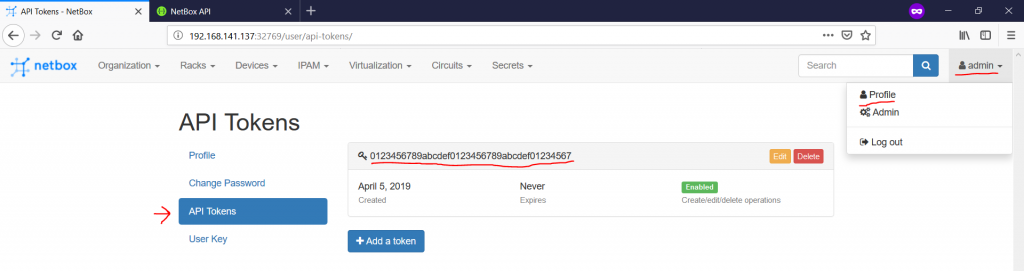
Summing up the API, it’s very extensive and makes it usable for Developers or DevOps. The last important, which you might have spotted in the curl part, is the token. Each user within NetBox has the token, which is associated with her/him. To get this token, you need to go to the corresponding tab within your profile from the main page of Netbox (“Username -> Profile -> API Tokens”):

Once you understand, how the API is working, you can start automation of your network.
Integrating Ansible with NetBox over REST API for device provisioning
We use neither NAPALM drivers here, nor any Python module, which creates dynamic inventory out of NetBox.
There are obviously numerous use cases, you can imagine, where integration of Ansible with Netbox could help. I will show you the following scenario. Assuming we have freshly booted network elements with just OOB management configured, we do the following:
- Read from the NetBox over REST API information about network devices, their ports, IP addresses and ASN names.
- Template the configuration for the underlying IP fabric (interfaces, IP addresses, BGP config).
- Push the templated configuration to the network elements
There are many different ways, how to implement this. I tried to make it as simple as possible, and here are my considerations:
- Avoid creation of Ansible inventory unless it’s absolutely necessary.
- Use Ansible network modules (nclu, eos_config, iosxr_config).
- Use Ansible roles.
The brief description of the Data Centre Fabric you can find on my GitHub page. The top-level parent playbook is quite simply:
2
3
4
5
6
7
8
---
- hosts: localhost
connection: local
gather_facts: yes
roles:
- dc_underlay
...
As you can see, it does nothing but just calling a single role. Point out, that we have localhost as hosts definition, what makes the role run against “localhost” from the Ansible inventory:
2
3
[linux]
localhost
All the important credentials and some parameters are saved in two files in “group_vars” for the “linux” group. The first one contains authentication parameters:
2
3
4
5
6
7
8
9
10
11
12
13
14
15
16
17
18
19
20
21
22
23
24
25
---
ansible_user: aaa
ansible_pass: N3tw0rk!
ansible_ssh_pass: N3tw0rk!
ansible_become_pass: N3tw0rk!
# Integration with NetBox
netbox_token: 0123456789abcdef0123456789abcdef01234567
# Day zero credentials Cumulus Linux
cumulus:
user: cumulus
pass: CumulusLinux!
# Day zero credentials Cisco IOS XR
cisco:
user: cisco
pass: cisco
# Day zero credentials Cumulus Linux
arista:
user: aaa
pass: aaa
...
And the second one contains some other useful variables:
2
3
4
5
6
7
8
9
10
11
12
13
14
15
---
# General vars
working_folder: /tmp/network_fabric
# Netbox integration
netbox_host: localhost
netbox_frontend_container: netboxdocker_nginx_1
# Some fabric parameters:
bgp:
password: DC_F@BR!C$
send: 10
receive: 30
...
All the useful work is performed by the role. The “main.yml” looks like as follows:
2
3
4
5
6
7
8
9
10
11
12
13
14
15
16
17
18
19
20
21
22
23
24
25
26
27
28
29
30
31
32
33
34
35
36
37
38
39
40
41
42
43
44
45
46
47
48
49
50
51
52
53
54
---
- name: CREATING TEMPORARY FOLDER
file:
dest: "{{ working_folder }}"
state: directory
- name: GETTING INFO ABOUT NETBOX CONTAINER
shell: "sudo docker container port {{ netbox_frontend_container }}"
become: yes
register: netbox_frontend_container_port
- name: SETTING API PORT
set_fact:
netbox_port: "{{ netbox_frontend_container_port.stdout | regex_replace('^.*:(\\d+)$', '\\1') }}"
- name: GETTING LIST OF DEVICES
uri:
url: "http://{{ netbox_host }}:{{ netbox_port }}/api/dcim/devices/"
method: GET
return_content: yes
headers:
accept: "application/json"
Authorization: "Token {{ netbox_token }}"
register: get_devices
- name: GETTING LIST OF ALL INTERFACES
uri:
url: "http://{{ netbox_host }}:{{ netbox_port }}/api/dcim/interfaces/?device={{ item.name }}"
method: GET
return_content: yes
headers:
accept: "application/json"
Authorization: "Token {{ netbox_token }}"
register: get_all_interfaces
loop: "{{ get_devices.json.results }}"
- name: GETTING LIST OF ALL IP ADDRESSES
uri:
url: "http://{{ netbox_host }}:{{ netbox_port }}/api/ipam/ip-addresses/?device={{ item.name }}"
method: GET
return_content: yes
headers:
accept: "application/json"
Authorization: "Token {{ netbox_token }}"
register: get_all_ip
loop: "{{ get_devices.json.results }}"
- name: STARTING CONFIGURATION LOOP
include_tasks: configuration_loop.yml
loop: "{{ get_devices.json.results }}"
loop_control:
loop_var: device_item
...
Step by step we do these actions:
- Create the temporary folder with the output files, which are used for configuration of the network elements.
- Get information about TCP port, where the Docker container with HTTP frontend of NetBox is running.
- Covert the data collected in the second step into variable with the port value.
- Collect the information about the all network devices from NetBox over REST API.
- Collect the information about all the ports (interfaces) from all network devices from NetBox over REST API.
- Collect the information about all IPv4 and IPv6 addresses from all network devices from NetBox over REST API.
- Launch configuration playbook.
The configuration playbook is relatively easy:
2
3
4
5
6
7
8
9
10
11
12
13
14
15
16
17
18
19
20
21
22
23
24
25
26
27
28
29
30
31
32
33
34
35
36
37
38
39
40
41
42
43
44
45
46
47
48
49
50
51
52
53
54
55
56
57
58
59
60
61
62
63
64
65
66
67
68
69
70
71
---
- name: CONFIGURATION LOOP // GETING PORTS CONFIG
uri:
url: "http://{{ netbox_host }}:{{ netbox_port }}/api/dcim/interfaces/?device={{ device_item.name }}"
method: GET
return_content: yes
headers:
accept: "application/json"
Authorization: "Token {{ netbox_token }}"
register: get_device_ports
- name: CONFIGURATION LOOP // GETING IP CONFIG
uri:
url: "http://{{ netbox_host }}:{{ netbox_port }}/api/ipam/ip-addresses/?device={{ device_item.name }}"
method: GET
return_content: yes
headers:
accept: "application/json"
Authorization: "Token {{ netbox_token }}"
register: get_device_ip
- name: CONFIGURATION LOOP // CREATING TEMPORARY FOLDER FOR {{ device_item.name }}
file:
dest: "{{ working_folder }}/{{ device_item.name }}"
state: directory
- name: CONFIGURATION LOOP // TEMPLATING CONFIG FOR {{ device_item.name }}
template:
src: "{{ device_item.platform.slug }}.j2"
dest: "{{ working_folder }}/{{ device_item.name }}/{{ device_item.name }}.conf"
- name: CONFIGURATION LOOP // CUMULUS // CONFIGURING {{ device_item.name }}
nclu:
atomic: yes
template: "{{ lookup('template', '{{ device_item.platform.slug }}.j2') }}"
ignore_errors: yes
ignore_unreachable: yes
delegate_to: "{{ device_item.primary_ip4.address | ipaddr('address') }}"
vars:
ansible_user: "{{ cumulus.user }}"
ansible_ssh_pass: "{{ cumulus.pass }}"
when: device_item.platform.slug == 'cumulus-linux'
- name: CONFIGURATION LOOP // ARISTA // CONFIGURING {{ device_item.name }}
local_action:
module: "eos_config"
authorize: true
save: true
src: "{{ working_folder }}/{{ device_item.name }}/{{ device_item.name }}.conf"
provider:
host: "{{ device_item.primary_ip4.address | ipaddr('address') }}"
username: "{{ arista.user }}"
password: "{{ arista.pass }}"
auth_pass: "{{ arista.pass }}"
ignore_errors: yes
ignore_unreachable: yes
when: device_item.platform.slug == 'arista-eos'
- name: CONFIGURATION LOOP // ARISTA // CONFIGURING {{ device_item.name }}
local_action:
module: "iosxr_config"
src: "{{ working_folder }}/{{ device_item.name }}/{{ device_item.name }}.conf"
provider:
host: "{{ device_item.primary_ip4.address | ipaddr('address') }}"
username: "{{ cisco.user }}"
password: "{{ cisco.pass }}"
ignore_errors: yes
ignore_unreachable: yes
when: device_item.platform.slug == 'cisco-ios-xr'
...
The tasks are accomplished by this playbook:
- First task is duplicating what was already done in the main playbook, so will be deprecated into the next release.
- The same as step one.
- We create temporary folder for each node we configure.
- Using Jinja2 template, which is initially created per-vendor, the configuration file for each network element is created
- Steps 5 -7 pushed the configuration to the third-party network element (using delegate_to for nclu or provider for eos_config/iosxr_config).
The first two tasks were initially used for Cumulus integration what has “remote-as external” knob. For Arista/Cisco it’s required to explicitly configure ASN for BGP peers, hence more complex template is needed. That’s why the collection of all data is moved to the “main.yml”.
As of today there are three templates available:
2
3
4
-rw-rw-r--. 1 aaa aaa 9854 Apr 8 22:19 arista-eos.j2
-rw-rw-r--. 1 aaa aaa 8202 Apr 9 08:58 cisco-ios-xr.j2
-rw-rw-r--. 1 aaa aaa 8654 Apr 7 18:43 cumulus-linux.j2
All of the vendors could be leaf, spine and border. Assuming that we have freshly created VMs with credentials according to “auth.yml” file and reachable over SSH on the management IPv4 addresses we can launch our master playbook:
2
3
4
5
6
7
8
9
10
11
12
13
14
15
16
17
18
19
20
21
22
23
24
25
PLAY [localhost] *********************************************************************************************************************************************
TASK [Gathering Facts] ***************************************************************************************************************************************
ok: [localhost]
TASK [dc_underlay : CREATING TEMPORARY FOLDER] ***************************************************************************************************************
changed: [localhost]
TASK [dc_underlay : GETTING INFO ABOUT NETBOX CONTAINER] *****************************************************************************************************
[WARNING]: Consider using 'become', 'become_method', and 'become_user' rather than running sudo
changed: [localhost]
TASK [dc_underlay : SETTING API PORT] ************************************************************************************************************************
ok: [localhost]
TASK [dc_underlay : GETTING LIST OF DEVICES] *****************************************************************************************************************
ok: [localhost]
!
! OUTPUT IS OMITTED
!
PLAY RECAP ***************************************************************************************************************************************************
localhost : ok=43 changed=16 unreachable=0 failed=0
Let’s check the IPv4 and IPv6 routing of any leaf (let’s say, on de-bln-leaf-101 running Cumulus Linux):
2
3
4
5
6
7
8
9
10
11
12
13
14
15
16
17
18
19
20
21
22
23
24
25
26
27
28
29
30
31
32
33
34
35
36
37
38
39
route : Static routes
route-map : Route-map
cumulus@de-bln-leaf-111:mgmt-vrf:~$ net show route ipv4
Codes: K - kernel route, C - connected, S - static, R - RIP,
O - OSPF, I - IS-IS, B - BGP, E - EIGRP, N - NHRP,
T - Table, v - VNC, V - VNC-Direct, A - Babel, D - SHARP,
F - PBR,
> - selected route, * - FIB route
B>* 10.1.1.1/32 [20/0] via 169.254.0.0, swp3, 00:04:05
C>* 10.1.1.101/32 is directly connected, lo, 00:10:02
B>* 10.1.1.102/32 [20/0] via 169.254.0.0, swp3, 00:03:12
B>* 10.1.1.103/32 [20/0] via 169.254.0.0, swp3, 00:04:05
B>* 10.1.1.104/32 [20/0] via 169.254.0.0, swp3, 00:04:05
B>* 10.1.1.105/32 [20/0] via 169.254.0.0, swp3, 00:04:05
C>* 169.254.0.0/31 is directly connected, swp3, 00:10:02
C>* 169.254.0.2/31 is directly connected, swp4, 00:10:02
C>* 169.254.1.0/30 is directly connected, peerlink.4094, 00:03:59
cumulus@de-bln-leaf-111:mgmt-vrf:~$ net show route ipv6
Codes: K - kernel route, C - connected, S - static, R - RIPng,
O - OSPFv3, I - IS-IS, B - BGP, N - NHRP, T - Table,
v - VNC, V - VNC-Direct, A - Babel, D - SHARP, F - PBR,
> - selected route, * - FIB route
C>* fc00:de:1::/127 is directly connected, swp3, 00:14:46
C>* fc00:de:1::2/127 is directly connected, swp4, 00:14:46
B>* fc00:de:1:1::1/128 [20/0] via fe80::250:56ff:fe29:6047, swp3, 00:08:49
C>* fc00:de:1:1::101/128 is directly connected, lo, 00:14:46
B>* fc00:de:1:1::102/128 [20/0] via fe80::250:56ff:fe29:6047, swp3, 00:07:56
B>* fc00:de:1:1::104/128 [20/0] via fe80::250:56ff:fe29:6047, swp3, 00:00:48
B>* fc00:de:1:1::105/128 [20/0] via fe80::250:56ff:fe29:6047, swp3, 00:08:49
C * fe80::/64 is directly connected, bridge, 00:08:43
C * fe80::/64 is directly connected, peerlink.4094, 00:08:43
C * fe80::/64 is directly connected, swp5, 00:14:46
C * fe80::/64 is directly connected, swp4, 00:14:46
C>* fe80::/64 is directly connected, swp3, 00:14:46
We see all the IPv4 and IPv6 loopbacks advertised and propagated respectively. It means that the underlay IP Fabric is up and running properly in our sample date centre.
The final configuration you can find on my GitHub page.

Lessons learned
Initially I started with the automation of the Cumulus and it was quite quick and smooth, as the BGP config is fairly easy. Then, for Cisco and Arista I have to change the algorithm, what makes things a bit more complicated, but the code is more robust.
The main lessons learned for me is that we shouldn’t be afraid to break everything we’ve built and built it from scratches, if we believe the outcome is worth do it.
Develop, test, break, make better.
Conclusion
I’ve learnt NetBox just recently, but I see it’s huge potential especially thanks to very reach REST API. It really uplifts the automation capability of your network to the new level. Moreover, the structure of NetBox itself is quite clean and straightforward making it great choice for infrastructure documentation. And what I’ve loved particularly is the possibility to extend standard documentation with JSON variables as much as far as you need. In future, you will see a couple of another articles, where we will use NetBox for documentation of the customer services.
Take care and good bye!
Support us
P.S.
If you have further questions or you need help with your networks, I’m happy to assist you, just send me message (https://karneliuk.com/contact/). Also don’t forget to share the article on your social media, if you like it.
BR,
Anton Karneliuk