

Hello my friend,
For a long time we haven’t posted blogs about pure network technologies. However, recently we were working on some interesting use case, which so far is not yet covered at a level of the working details nowhere in the internet. As such, we decided to share with you our findings and working details.
2
3
4
5
retrieval system, or transmitted in any form or by any
means, electronic, mechanical or photocopying, recording,
or otherwise, for commercial purposes without the
prior permission of the author.
How automation can help with SR-TE in SP network?
In some (big) networks the BGP-SR-TE is a good signal the SR-TE policies, so that the PE routers can build the SR-TE tunnels without the need to configure them locally. However, the BGP-SR-TE requires a full pledged SDN controller, so that you can generate the SR-TE policy in the backend using some UI/API and send the policies down to the network elements using the BGP. If you want to have a somewhat simpler setup, you may need need to deploy the tunnels manually. In this case, the automation is your closest ally as it can take the burden of the configuration generation and rolling it out to your devices.
In our trainings, the Live Network Automation Training (10 weeks) and Automation with Nornir (2 weeks), we explore a lot of real use cases, where the automation helps you to validate the state of you network and change it if necessary. You will learn the whole spectre of the automation approaches starting from the text-based automation used in the hyper scalers with the full configuration templated till the model-driven automation with NETCONF/RESTCONF/gNMI loaded with YANG data models for Cisco, Nokia, Arista and Cumulus. This knowledge comes with a lot of different exercises with direct console as well as Ansible/Python and Bash scripts. On top to that, you learn a lot of infrastructure skills such as building and managing Linux, KVM and Docker.
Moreover, we are running our trainings for 2 years already and constantly adopting them to the changes happening in the automation world. Master your automation skills with us.
Brief description
The Segment Routing Traffic Engineering (SR-TE) tunnels are the important building blocks of the modern Service Provider networks and/or Data Centre DCIs. Long ago we already covered the SR-TE tunnels in Nokia SR and Cisco IOS XR based network devices. One the problem we were not able solve that time was the absence of the mechanism on the PE router to check if the tunnel is alive or not. See the following picture for better understanding.

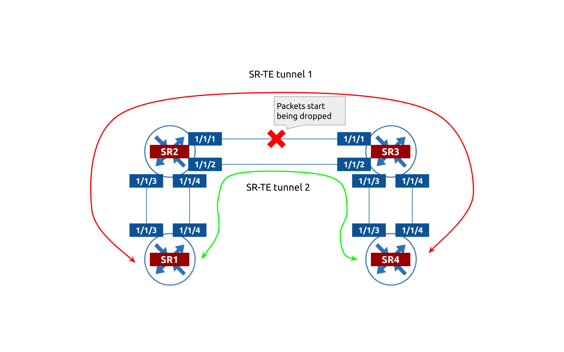
The SR-TE tunnel by default doesn’t have a built-in mechanism to check the connectivity end-to-end, as it is just being computed at the head end router and installed in RIB. Looking into the example above, say, the SR1 has 2 SR-TE tunnels to SR4, which have path diversity and computed using the SR Adj SIDs. If link SR2 (1/1/1) – SR3 (1/1/1) is down, the SR1 doesn’t invalidate the red SR-TE tunnel and sends traffic to SR2 for it, whereas SR2 starts dropping the, as the the corresponding Adj SID points to the interface, which is down.
In contrast. the RSVP-TE is being signalled and periodically sends keep alive messages. As such, it would be able to spot this issue. Does it mean that RSVP-TE being much older than SR-TE is better? Well, not really…
There are multiple solutions, how you can solve problem:
- You can deploy SDN controller, where you can signal the topology of the network using the BGP-LS and use the PCEP to signal tunnels. The solution is viable, but is very complex and requires a lot of investment (time or money).
- You can add the possibility to SR-TE tunnels to send the end-to-end health checks.
Back in the days, it was not really possible. However, now we can achieve that using the Seamless BFD (S-BFD). In a nutshell, S-BFD is a modified version of the BFD to address the scalability issue. In Nokia SR OS, it requires way more configuration than a regular BFD, but this is the only option to make the SR-TE adaptive to the link failures. The good thing is that you can tune performance to notice failures very quickly (matter of milliseconds) so that you can do a failure quickly.
Network setup
Let’s take a look in the sample lab setup we used to test the solution:

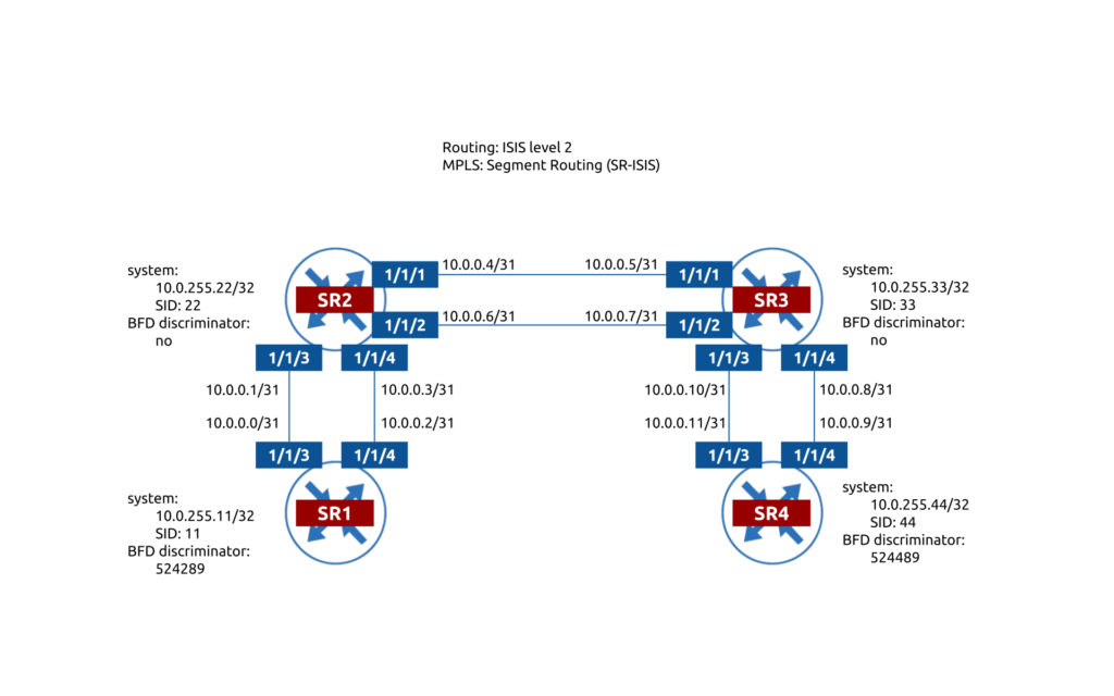
We don’t show in this article the basic configuration of ISIS or Segment Routing as it is expected you already know how it works. Instead, we are focusing only on the SR-TE and seamless BFD. The IP addressing is relatively straightforward as well as schema of the SR SID’s and BFD discriminators used in the seamless BFD (see below for further details).
Refer to the corresponding article to learn how to configure ISIS or Segment Routing.
Usage
This part covers the details of the configuration of the overall solution. The full configuration is split into 2 big parts, which is the configuration of the seamless BFD framework and the SR-TE policies on top.
#1. Configuration of Seamless BFD
The first step is to configure the Seamless BFD. Generally, its configuration is covered in the corresponding configuration guide. However, the level of details is a little bit low, so we decided to go deeper.
From the configuration perspective, the seamless BFD consist of the two elements:
- Reflector part (configured on the tail-end router for the SR-TE tunnel).
- Peer part (configured on the head-end router).
#1.1. Reflector configuration
In contrast to an “ordinary” BFD, where the discriminator is automatically allocated for each BGP session, for the seamless BFD it shall be configured manually. The following configuration is implemented on SR1:
2
3
4
5
6
7
8
9
10
11
bfd {
seamless-bfd {
reflector "SR1" {
admin-state enable
discriminator 524289
local-state up
}
}
}
}
Each host shall have its own discriminator, so on the other side of the SR-TE, the SR-TE shall have a different number:
2
3
4
5
6
7
8
9
10
11
bfd {
seamless-bfd {
reflector "SR4" {
admin-state enable
discriminator 524489
local-state up
}
}
}
}
#1.2. Seamless BFD peer configuration
The second part of the seamless BFD configuration is the peer: for SR4 the peer is SR1 and for SR1 the peer is SR4 in our topology. The seamless BFD session is destined to the system interface, so pay attention to the topology above for the details of the IP/discriminator mapping. E.g., from SR1 you need to configure the IP address of the SR4 system’s interface and SR4 discriminator as seamless BFD peer.
2
3
4
5
6
7
8
9
10
11
router "Base" {
bfd {
seamless-bfd {
peer 10.0.255.44 {
discriminator 524489
}
}
}
}
}
And on the other side:
2
3
4
5
6
7
8
9
10
11
router "Base" {
bfd {
seamless-bfd {
peer 10.0.255.11 {
discriminator 524289
}
}
}
}
}
At this stage, we have created the configuration of the peers. However, they won’t be operational before we map it to the SR-TE policies.
#2. Configuration of SR-TE policies with Seamless BFD
The mapping of the seamless BFD session to the SR-TE tunnel consist of two steps: creating a BFD policy and applying it to the SR-TE LSP.
#2.1. Configuration of the BFD policy
Generally, this configuration shall be applied on the head-end router. However, in our cases the SR-TE tunnels are bidirectional (well, two unidirectional). Therefore, the same configuration shall be created and applied both for SR1 and SR4 ends:
2
3
4
5
6
7
8
9
10
11
12
13
router "Base" {
bfd {
bfd-template "SR_TE_STRICT_TUNNEL" {
echo-receive 100
multiplier 3
receive-interval 50
transmit-interval 50
type cpm-np
}
}
}
}
#2.2. Mapping the BFD policy to SR-TE tunnel
Final configuration step is to map the created policy to the SR-TE LSP. Here is the configuration of the two SR-TE tunnels with the explicit paths and enabled BFD policies from SR1 to SR4 (configuration from SR4 to SR1 will be mirrored):
2
3
4
5
6
7
8
9
10
11
12
13
14
15
16
17
18
19
20
21
22
23
24
25
26
27
28
29
30
31
32
33
34
35
36
37
38
39
40
41
42
43
44
45
46
47
48
49
50
51
52
53
54
55
56
57
58
59
60
61
62
63
64
65
66
67
A:SR1# info
admin-state enable
path "SR4_explicit_1" {
admin-state enable
hop 1 {
ip-address 10.0.0.1
type strict
}
hop 2 {
ip-address 10.0.0.5
type strict
}
hop 3 {
ip-address 10.0.0.9
type strict
}
}
path "SR4_explicit_2" {
admin-state enable
hop 1 {
ip-address 10.0.0.3
type strict
}
hop 2 {
ip-address 10.0.0.7
type strict
}
hop 3 {
ip-address 10.0.0.11
type strict
}
}
lsp "SR4_strict_1" {
admin-state enable
type p2p-sr-te
to 10.0.255.44
metric 25
path-computation-method local-cspf
max-sr-labels {
additional-frr-labels 4
}
bfd {
bfd-liveness true
bfd-template "SR_TE_STRICT_TUNNEL"
failure-action failover-or-down
}
primary "SR4_explicit_1" {
}
}
lsp "SR4_explicit_2" {
admin-state enable
type p2p-sr-te
to 10.0.255.44
metric 25
path-computation-method local-cspf
max-sr-labels {
additional-frr-labels 4
}
bfd {
bfd-liveness true
bfd-template "SR_TE_STRICT_TUNNEL"
failure-action failover-or-down
}
primary "SR4_explicit_2" {
}
}
The overall logic here is that you have two independent explicit paths, which are converted into the label stack using the adjacent labels. Then each LSP is mapped to a single explicit path and have the BFD template enabled. The BFD template should have an action failure-or-down, which means that the LSP will be brought down in case that BFD packets sent inside the MPLS tunnel are not returned as plain IP traffic.
#2.3. Fallback scenario
If you carefully take a look on the topology and think about the failure scenarios, you can figure out that there are multiple cases where two outages may result in full traffic loss. For such cases we implemented the fallback to the SR-ISIS, where no load sharing is available, but connectivity continues working.
#3. Validation
The validation of such service consist from the control plane and data plane verifications.
#3.1 Control plane
You can check the the SR-TE LSP as follows:
2
3
4
5
6
7
8
9
10
11
12
13
14
15
16
17
18
19
20
21
22
23
24
25
26
27
28
29
30
31
32
33
34
35
36
37
38
39
40
41
42
43
44
45
46
47
48
49
50
51
===============================================================================
MPLS SR-TE LSPs (Originating) (Detail)
===============================================================================
Legend :
+ - Inherited
===============================================================================
-------------------------------------------------------------------------------
Type : Originating
-------------------------------------------------------------------------------
LSP Name : SR1_strict_1
LSP Type : SrTeLsp LSP Tunnel ID : 8
LSP Index : 65543 TTM Tunnel Id : 655369
From : 10.0.255.11
To : 10.0.255.11
Adm State : Up Oper State : Up
LSP Up Time : 14d 16:01:59 LSP Down Time : 0d 00:00:00
Transitions : 33 Path Changes : 33
Retry Limit : 0 Retry Timer : 30 sec
Hop Limit : 255 Negotiated MTU : 9178
PathCompMethod : none
Metric : 25
Local Sr Protec*: preferred Label Stack Reduction: Disabled
Load Bal Wt : N/A ClassForwarding : Disabled
Include Grps : Exclude Grps :
None None
Egress Stats : Disabled
BFD Template : SR_TE_STRICT_TUNNEL BFD Ping Intvl : N/A
BFD Enable : True BFD Failure-action : FailoverOrDn
WaitForUpTimer : 4
Revert Timer : Disabled Next Revert In : N/A
Entropy Label : Enabled+ Oper Entropy Label : Enabled
Negotiated EL : Disabled
VprnAutoBind : Enabled
IGP Shortcut : Enabled BGP Shortcut : Enabled
IGP LFA : Disabled IGP Rel Metric : Disabled
BGPTransTun : Enabled
Oper Metric : 25
PCE Report : Disabled+
PCE Control : Disabled
Max SR Labels : 6 Additional FRR Labels: 4
Path Profile : None
Admin Tags : None
Primary(a) : SR1_explicit_1
Up Time : 14d 16:01:59
Bandwidth : 0 Mbps
===============================================================================
* indicates that the corresponding row element may have been truncated.
You see that the BFD is enabled and up. To check the status of the seamless BFD session use:
2
3
4
5
6
7
8
9
10
11
12
13
14
15
16
17
18
19
20
21
22
23
24
25
26
27
28
29
30
===============================================================================
BFD Session
===============================================================================
Prefix : 10.0.255.11/32
Local Address : 10.0.255.44
LSP Name : SR1_strict_1
LSP Index : 65543 Path LSP ID : 54274
Fec Type : srTe
Oper State : Up Protocols : mplsLsp
Up Time : 14d 16:03:56 Up Transitions : 1
Down Time : None Down Transitions : 0
Version Mismatch : 0
Forwarding Information
Local Discr : 28 Local State : Up
Local Diag : 0 (None)
Local Mode : Demand
Local Min Tx : 50 Local Mult : 3
Last Sent (ms) : 11 Local Min Rx : 50
Type : cpm-np
Remote Discr : 524289 Remote State : Up
Remote Diag : 0 (None) Remote Mode : Async
Remote Min Tx : 50 Remote Mult : 3
Remote C-flag : 1
Last Recv (ms) : 3 Remote Min Rx : 3
===============================================================================
===============================================================================
You can also validate the full list of the active seamless BFD sessions:
2
3
4
5
6
7
8
9
10
11
12
13
14
15
16
17
18
19
20
21
22
23
24
25
===============================================================================
Legend:
Session Id = Interface Name | LSP Name | Prefix | RSVP Sess Name | Service Id
wp = Working path pp = Protecting path
===============================================================================
BFD Session
===============================================================================
Session Id State Tx Pkts Rx Pkts
Rem Addr/Info/SdpId:VcId Multipl Tx Intvl Rx Intvl
Protocols Type LAG Port LAG ID
Loc Addr
-------------------------------------------------------------------------------
10.0.255.44/32 Up N/A N/A
10.0.255.44 3 50 50
mplsLsp cpm-np N/A N/A
10.0.255.11
10.0.255.44/32 Up N/A N/A
10.0.255.44 3 50 50
mplsLsp cpm-np N/A N/A
10.0.255.11
-------------------------------------------------------------------------------
No. of BFD sessions: 2
===============================================================================
#3.2 Data plane
The validation of the date plane is pretty straightforward. As long as you shut down one of the links on one path, the traffic is switched to a second LSP and vice versa within 150 ms, so customer’s traffic is slightly affected.
Cooperation
This solution was created with the cooperation with Pau Nadeu Rabat and implemented in the Service Provider Network in Spain. Thanks a lot for an opportunity to work together on that.
Lessons learned
Back in the days (2019) I was already testing the SR-TE tunnels in the Vodafone. However, that days the seamless BFD was doing just its first steps and it was not yet supported in the production images of the network operation systems. It was quite an interesting exercise to brush up that experience and learn how the pure service provider technologies has evolved since that time.
Conclusion
The Segment Routing and Segment Routing Traffic Engineering are the key building blocks of modern service provider networks. However, SR-TE lacks the mechanism of the end-to-end path validation, which existed in RSVP-TE. The seamless BFD fixes this issue, so that together they provide the high level or programmability and resiliency. Take care and good bye.
Support us
P.S.
If you have further questions or you need help with your networks, our team is happy to assist you. Just book a free slot with us. Also don’t forget to share the article on your social media, if you like it.
BR,
Anton Karneliuk