MPLS / RSVP-TE in Nokia (Alcatel-Lucent) SR OS and Cisco IOS XR
Anton Karneliuk
Hello my friend,
So far we have reviewed two technology of building MPLS data plane (transport tunnel in Nokia (Alcatel-Lucent) terminology) that are LDP and BGP labeled unicast. Today we continue our journey with the third option, which is called RSVP-TE and provides you wide possibilities for Traffic Engineering (TE).
Disclaimer
Nokia (Alcatel-Lucent) SR OS has option to build so called “non-TE” RSVP-based MPLS tunnels (LSP – label switched path). In this case you don’t have to enable IGP extensions (OSPF-TE or ISIS-TE), but you don’t have all fancy features like link coloring, SRLG, Fast Reroute and so on. Moreover this option isn’t interoperable with Cisco IOS XR, and to be frank, I don’t know another vendor, who supports it. So in this article we’ll configure “ordinary” TE MPLS tunnel that implies creation and usage of TED (Traffic Engineering Database).
Topology
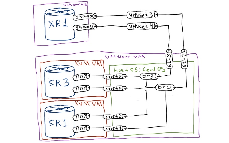
The physical topology remains the same as always:
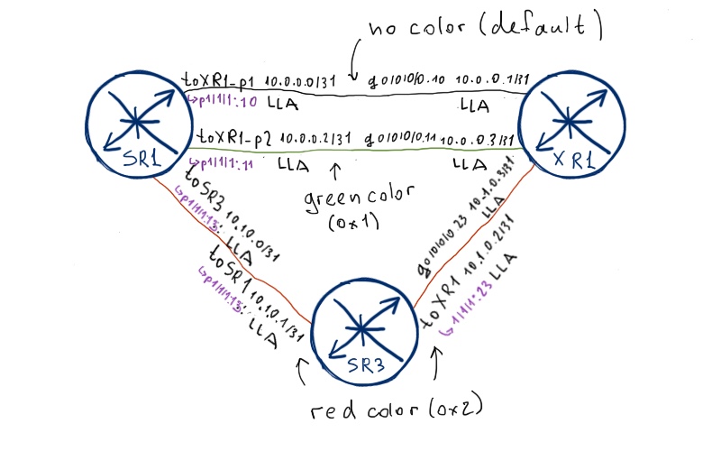
The logical topology was also used previously in LDP article:
The initial configuration we’ll use also from that article. It will be easier for you to compare the configuration and operation of two different MPLS-forming technologies in the same conditions:
Preparation for building LSP (MPLS tunnel)
First of all we need to enable support of MPLS traffic engineering and RSVP in our network. To achieve it we’ll activate TE extension to routing protocol (as IGP we use ISIS, but the configuration for OSPF is pretty similar). Afterwards we enable RSVP and MPLS at all interfaces as all of them take part in our MPLS forwarding plane:
Nokia (Alcatel-Lucent) VSR (SR 7750)
Cisco IOS XR (ASR 9000)
SR1
XR1
A:SR1>config>router# info
—————————
isis
traffic-engineering
exit
mpls
interface “system”
no shutdown
exit
interface “toSR3”
no shutdown
exit
interface “toXR1_p1”
no shutdown
exit
interface “toXR1_p2”
no shutdown
exit
no shutdown
exit
rsvp
no shutdown
exit
—————————
A:SR3>config>router# info
—————————
isis
traffic-engineering
exit
mpls
interface “system”
no shutdown
exit
interface “toSR1”
no shutdown
exit
interface “toXR1”
no shutdown
exit
no shutdown
exit
rsvp
no shutdown
exit
—————————
I assume that some explanation and verification is needed before we go further, as Nokia (Alcatel-Lucent) SR OS and Cisco IOS XR behaves a little bit different:
Nokia (Alcatel-Lucent) SR OS
Cisco IOS XR
ISIS-TE extension
You simple enable TE and that’s it. Router-id is derived from global routing configuration
You chose for which level you want activate TE extension and chose interface for router-id
RSVP
Interfaces are automatically derived from MPLS context. Reservable BW is derived from capacity of physical port associated with interface.
Interfaces and reservable BW must be explicitly configured.
MPLS TE
MPLS LDP must be activated for proper operation. MPLS OAM must be explicitly activated.
So these differences in behavior must be taken into account during configuration of MPLS/RSVP-TE in multivendor network based on Nokia (Alcatel-Lucent) SR OS and Cisco IOS XR.
After we’ve applied the configuration above, we can check if our interfaces are operational in MPLS and RSVP contexts. In Nokia (Alcatel-Lucent) SR OS you can check it as follows:
A:SR1# show router mpls interface
============================================================================
MPLS Interfaces
============================================================================
Interface Port-id Adm Opr TE-metric
—————————————————————————-
system system Up Up None
. Admin Groups None
. SRLG Groups None
toSR3 1/1/1:13 Up Up None
. Admin Groups None
. SRLG Groups None
toXR1_p1 1/1/1:10 Up Up None
. Admin Groups None
. SRLG Groups None
toXR1_p2 1/1/1:11 Up Up None
. Admin Groups None
. SRLG Groups None
—————————————————————————-
Interfaces : 4
============================================================================
!
!
A:SR1# show router rsvp interface
============================================================================
RSVP Interfaces
============================================================================
Interface Total Active Total BW Resv BW Adm Opr
.Sessions Sessions (Mbps) (Mbps)
—————————————————————————-
system – – – – Up Up
toSR3 0 0 1000 0 Up Up
toXR1_p1 0 0 1000 0 Up Up
toXR1_p2 0 0 1000 0 Up Up
—————————————————————————-
Interfaces : 4
============================================================================
In Cisco IOS XR the output of the command “show mpls interfaces” shows all type of protocols that can be used for build MPLS data plane, where “tunnel” means MPLS traffic engineering. In Nokia (Alcatel-Lucent) SR OS the output of “show router mpls interfaces” shows operation of interfaces for RSVP-TE based MPLS.
You can refer to article about LDP, where we haven’t activated MPLS context at Nokia (Alcatel-Lucent) VSR (SR 7750).
The next interesting point, what should be checked and what will be actively used, is TED (traffic engineering database). It’s information is distributed using ISIS updates in specific TLVs, so ISIS database is what we need. I’ll provide only part of this LSP (link-state packet in case of ISIS) that is related traffic engineering, because the whole LSP is really big:
In Cisco IOS XR you can use the very similar command “show isis database SR1.00-00 verbose” to see the detailed structure of LSP. But there is another useful command available at Cisco IOS XR:
I’ve reduced the output just to one node, as basically you see all nodes and their interconnection. So this is the actual TED built using information extracted from ISIS. If you omit keyword “brief”, you’ll see detailed information including BW utilization per priority.
The last thing that I want to show you, before going to MPLS tunnels themselves, is the CSPF tool in Nokia (Alcatel-Lucent) SR OS. It’s really powerful tool that allow you to determine the actual path of LSP from point head-end to tail-end MPLS router based on the mentioned constrains. This provide you valuable input on possible path before you configure (or activate) LSP. Take a look at the basic example:
As constrains for example we added that we want to avoid certain next-hop and reserved BW should 567 Mbps. Pay attention that we do this calculation at SR3, though we are determining path between SR1 and XR1. It’s possible because all the routers has the same TED across the RSVP-TE domain, otherwise MPLS-TE won’t work.
Basic RSVP-TE LSP
Let’s shutdown the direct links between SR1 and XR3 so that the only available path between them pass SR3.
Now we can proceed with the establishment of MPLS LSP (label switch path) or MPLS tunnel from Nokia (Alcatel-Lucent) SR OS router SR1 to Cisco IOS XR router XR1. As the first step the LSP will be quite simple without any constrains (though it will be CSPF enabled in terms of Nokia (Alcatel-Lucent).
Nokia (Alcatel-Lucent) VSR (SR 7750)
Cisco IOS XR (ASR 9000)
SR1
XR1
A:SR1>config>router# info
—————————
mpls
path “loose”
no shutdown
exit
lsp “SR1_to_XR1”
to 10.0.255.2
cspf
primary “loose”
exit
no shutdown
exit
no shutdown
exit
—————————
We’ve configured appropriate logging at SR1 and SR3 in order see the RSVP-TE and MPLS LSP operation in the real time.
In Nokia (Alcatel-Lucent) SR OS you create a separate object called “path”, which is a key component of MPLS LSP. You must enable it before enabling LSP, otherwise LSP will be operationally down. The only parameter that can be configured inside path is explicit path (we’ll talk about it later), and if there are no hops configured the path is considered to be totally loose and TED will be consulted to build exact path to destination. Keyword “cspf” means that TED will be used. As a source of MPLS LSP the system interface of the Nokia (Alcatel-Lucent) VSR (SR 7750) is used.
In Cisco IOS XR you manually mentioned, which interface should be used as source for MPLS tunnel. “Autoroute destination” mean that route to destination IP will be installed in routing table and will be available for routing look up for all other protocols. Also in Cisco IOS XR you have to explicitly enable “record-route” in order RRO to be built. “Path-option dynamic” in IOS XR equals “primary loose” in SR OS.
Just after you bring up (enters “no shutdown”) at MPLS LSP SR1_to_XR1 configured at SR1, you see the following log messages:
SR OS:
5 2016/10/11 20:04:42.93 UTC WARNING: MPLS #2003 Base VR 1:
“Tunnel loose is operationally enabled (‘no shutdown’)”
6 2016/10/11 20:05:42.17 UTC WARNING: MPLS #2011 Base VR 1:
“LSP path SR1_to_XR1::loose is operationally enabled (‘no shutdown’)”
7 2016/10/11 20:05:42.17 UTC WARNING: MPLS #2009 Base VR 1:
“LSP SR1_to_XR1 is operationally enabled (‘no shutdown’)”
!
!
IOS XR:
RP/0/0/CPU0:Sep 29 04:42:01.984 : te_control[1051]: %ROUTING-MPLS_TE-5-LSP_UPDOWN : tail (signalled-name: SR1_to_XR1::loose, LSP Id: 4608) state changed to up
The similar messages you see, when you make commit at Cisco IOS XR and configuration of MPLS tunnel is being applied. LSP is up and running, but before checking it lets overview some useful commands for trouble shooting.
A:SR1# show router rsvp session
============================================================================
RSVP Sessions
============================================================================
From To Tunnel LSP Name State
. ID ID
—————————————————————————-
10.0.255.1 10.0.255.2 1 4608 SR1_to_XR1::loose Up
10.0.255.2 10.0.255.1 21 3 XR1_t21 Up
—————————————————————————-
Sessions : 2
============================================================================
!
!
A:SR3# show router rsvp session
============================================================================
RSVP Sessions
============================================================================
From To Tunnel LSP Name State
. ID ID
—————————————————————————-
10.0.255.1 10.0.255.2 1 4608 SR1_to_XR1::loose Up
10.0.255.2 10.0.255.1 21 3 XR1_t21 Up
—————————————————————————-
Sessions : 2
============================================================================
!
!
RP/0/0/CPU0:XR1#show rsvp session
Type Destination Add DPort Proto/ExtTunID PSBs RSBs Reqs
—- ————— —– ————— —– —– —–
LSP4 10.0.255.1 21 10.0.255.2 1 1 0
LSP4 10.0.255.2 1 10.0.255.1 1 1 1
The output above shows you that all the routers along the path participates in RSVP. For each MPLS LSP there is a separate RSVP session. The most important information here is triplet “To/destination address” – “Tunnel ID/DPort” – “From/ExtTunID”, what forms SESSION object in RSVP and uniquely identifies MPLS LSP. This triplets remains stable until restart in Nokia (Alcatel-Lucent) SR OS. In Cisco IOS XR it remains the same even after restart, because you manually configure tunnel ID. At the same time LSP ID increases each time the tunnel flaps or is reoptimized (resignaled in Nokia (Alcatel-Lucent) terms).
For sure we are interested in the details, and one of the most interesting one is MPLS label that is used for traffic forwarding. You can check it as follows:
A:SR1# show router rsvp session detail | match expression “LSP|Label|From|Hop|Interface”
LSP : XR1_t21
From : 10.0.255.2 To : 10.0.255.1
Tunnel ID : 21 LSP ID : 4
In Interface : 1/1/1:13 Out Interface : n/a
In Label : 262143 Out Label : n/a
Previous Hop : 10.1.0.1 Next Hop : n/a
LSP Attr Flags : N/A
LSP : SR1_to_XR1::loose
From : 10.0.255.1 To : 10.0.255.2
Tunnel ID : 1 LSP ID : 54272
In Interface : n/a Out Interface : 1/1/1:13
In Label : n/a Out Label : 262142
Previous Hop : n/a Next Hop : 10.1.0.1
Hops :
. No Hops Specified
LSP Attr Flags : N/A
!
!
A:SR3# show router rsvp session detail | match expression “LSP|Label|From|Hop|Interface”
LSP : XR1_t21
From : 10.0.255.2 To : 10.0.255.1
Tunnel ID : 21 LSP ID : 4
In Interface : 1/1/1:23 Out Interface : 1/1/1:13
In Label : 262143 Out Label : 262143
Previous Hop : 10.1.0.3 Next Hop : 10.1.0.0
LSP Attr Flags : N/A
LSP : SR1_to_XR1::loose
From : 10.0.255.1 To : 10.0.255.2
Tunnel ID : 1 LSP ID : 54272
In Interface : 1/1/1:13 Out Interface : 1/1/1:23
In Label : 262142 Out Label : 3
Previous Hop : 10.1.0.0 Next Hop : 10.1.0.3
LSP Attr Flags : N/A
!
!
SESSION: IPv4-LSP Addr: 10.0.255.1, TunID: 21, ExtID: 10.0.255.2
. LSPId: 3
. InLabel: No intf, No label
. OutLabel: GigabitEthernet0/0/0/0.23, 262142
. FRR OutLabel: No intf, No label
SESSION: IPv4-LSP Addr: 10.0.255.2, TunID: 1, ExtID: 10.0.255.1
. LSPId: 4608
. InLabel: GigabitEthernet0/0/0/0.23, 3
. OutLabel: No intf, No label
. FRR OutLabel: No intf, No label
Remember, value “3” for Label means implicit NULL and calls penultimate hop popping (PHP) at pre-last hop router. By default Cisco IOS XR signals this label and Nokia (Alcatel-Lucent) SR OS not.
Output of RSVP-TE show commands contains the information from control plane (to be more precise – LIB (Label Information Base)). To check forwarding plane including MPLS labels for configured LSPs, we have another option:
A:SR1# show router mpls lsp detail terminate
============================================================================
MPLS LSPs (Terminate) (Detail)
============================================================================
—————————————————————————-
LSP XR1_t21
—————————————————————————-
From : 10.0.255.2 To : 10.0.255.1
State : Up
SetupPriority : 7 Hold Priority : 7
Class Type : 0
In Interface : 1/1/1:13 In Label : 262143
Previous Hop : 10.1.0.1
============================================================================
!
!
A:SR3# show router mpls lsp transit detail
============================================================================
MPLS LSPs (Transit) (Detail)
============================================================================
—————————————————————————-
LSP XR1_t21
—————————————————————————-
From : 10.0.255.2 To : 10.0.255.1
State : Up
SetupPriority : 7 Hold Priority : 7
Class Type : 0
In Interface : 1/1/1:23 In Label : 262143
Out Interface : 1/1/1:13 Out Label : 262143
Previous Hop : 10.1.0.3 Next Hop : 10.1.0.0
Reserved BW : 0 Kbps
—————————————————————————-
LSP SR1_to_XR1::loose
—————————————————————————-
From : 10.0.255.1 To : 10.0.255.2
State : Up
SetupPriority : 7 Hold Priority : 0
Class Type : 0
In Interface : 1/1/1:13 In Label : 262142
Out Interface : 1/1/1:23 Out Label : 3
Previous Hop : 10.1.0.0 Next Hop : 10.1.0.3
Reserved BW : 0 Kbps
============================================================================
In Nokia (Alcatel-Lucent) SR OS you need add specific keyword “transit” or “detail” to see the state of MPLS tunnel, if LSP doesn’t start at the device.
In MPLS/RSVP-TE model the most interesting and complex work is done at the head-end router that is router that calculates and establishes LSP. There will be big output following. At Nokia (Alcatel-Lucent) VSR (SR 7750) the details of establishing LSP you can check in the following command:
A:SR1# show router mpls lsp path detail
============================================================================
MPLS LSP Path (Detail)
============================================================================
Legend :
@ – Detour Available # – Detour In Use
b – Bandwidth Protected n – Node Protected
s – Soft Preemption
S – Strict L – Loose
A – ABR
============================================================================
—————————————————————————-
LSP SR1_to_XR1 Path loose
—————————————————————————-
LSP Name : SR1_to_XR1
Path LSP ID : 54272
From : 10.0.255.1 To : 10.0.255.2
Admin State : Up Oper State : Up
Path Name : loose Path Type : Primary
Path Admin : Up Path Oper : Up
Out Interface : 1/1/1:13 Out Label : 262142
Path Up Time : 0d 00:34:59 Path Down Time : 0d 00:00:00
Retry Limit : 0 Retry Timer : 30 sec
Retry Attempt : 0 Next Retry In : 0 sec
BFD Template : None BFD Ping Interval : 60
BFD Enable : False
—
Adspec : Disabled Oper Adspec : Disabled
CSPF : Enabled Oper CSPF : Enabled
Least Fill : Disabled Oper LeastFill : Disabled
FRR : Disabled Oper FRR : Disabled
Propogate Adm Grp : Disabled Oper Prop Adm Grp : Disabled
Inter-area : False
—-
Neg MTU : 500 Oper MTU : 500
Bandwidth : No Reservation Oper Bandwidth : 0 Mbps
Hop Limit : 255 Oper HopLimit : 255
Record Route : Record Oper Record Route : Record
Record Label : Record Oper Record Label : Record
Setup Priority : 7 Oper Setup Priority : 7
Hold Priority : 0 Oper Hold Priority : 0
Class Type : 0 Oper CT : 0
Backup CT : None
MainCT Retry : n/a
Rem :
MainCT Retry : 0
Limit :
Include Groups : Oper Include Groups :
None None
Exclude Groups : Oper Exclude Groups :
None None
—-
Adaptive : Enabled Oper Metric : 20
Preference : n/a
Path Trans : 1 CSPF Queries : 1
Failure Code : noError
Failure Node : n/a
Explicit Hops :
. No Hops Specified
Actual Hops :
. 10.1.0.0 (10.0.255.1) Record Label : N/A
-> 10.1.0.1 (10.0.255.3) Record Label : 262142
-> 10.1.0.3 (10.0.255.2) Record Label : 3
Computed Hops :
. 10.1.0.0(S)
-> 10.1.0.1(S)
-> 10.1.0.3(S)
Resignal Eligible: False
Last Resignal : n/a CSPF Metric : 20
============================================================================
There are a lot information above, so I advise you to spend some time here to familiarize yourself, if you aren’t. For now the most interesting information is two fields: “Computed Hops” and “Actual hops”. In “Computed hops” you see the results of CSPF calculation upon MPLS LSP establishment. In RSVP PATH messages these hops are copied to ERO (Explicit Route Object), which is analyzed by each router along the path from head-end to tail-end router. “Actual hops” contains information from RRO (Record Route Object) extracted from RSVP RESV message. These hops are identical, what is correct. Now let’s take a look at information that Cisco IOS XR tells us regarding its tunnel:
RP/0/0/CPU0:XR1#show mpls traffic-eng tunnels detail
Name: tunnel-te21 Destination: 10.0.255.1 Ifhandle:0x1a80
. Signalled-Name: XR1_t21
. Status:
. Admin: up Oper: up Path: valid Signalling: connected
. path option 10, type dynamic (Basis for Setup, path weight 20)
. G-PID: 0x0800 (derived from egress interface properties)
. Bandwidth Requested: 0 kbps CT0
. Creation Time: Thu Sep 29 05:58:56 2016 (01:01:24 ago)
. Config Parameters:
. Bandwidth: 0 kbps (CT0) Priority: 7 7 Affinity: 0x0/0xffff
. Metric Type: TE (default)
. Path Selection:
. Tiebreaker: Min-fill (default)
. Hop-limit: disabled
. Cost-limit: disabled
. Path-invalidation timeout: 45000 msec (default), Action: Tear (default)
. AutoRoute: disabled LockDown: disabled Policy class: not set
. Forward class: 0 (default)
. Forwarding-Adjacency: disabled
. Loadshare: 0 equal loadshares
. Auto-bw: disabled
. Fast Reroute: Disabled, Protection Desired: None
. Path Protection: Not Enabled
. BFD Fast Detection: Disabled
. Reoptimization after affinity failure: Enabled
. Soft Preemption: Disabled
. SNMP Index: 23
. Binding SID: None
. History:
. Tunnel has been up for: 00:33:14 (since Thu Sep 29 06:27:06 UTC 2016)
. Current LSP:
. Uptime: 00:33:14 (since Thu Sep 29 06:27:06 UTC 2016)
. Reopt. LSP:
. Last Failure:
. LSP not signalled, identical to the [CURRENT] LSP
. Date/Time: Thu Sep 29 06:45:37 UTC 2016 [00:14:43 ago]
. Prior LSP:
. ID: 3 Path Option: 10
. Removal Trigger: path verification failed
. Current LSP Info:
. Instance: 4, Signaling Area: IS-IS CORE level-2
. Uptime: 00:33:14 (since Thu Sep 29 06:27:06 UTC 2016)
. Outgoing Interface: GigabitEthernet0/0/0/0.23, Outgoing Label: 262143
. Router-IDs: local 10.0.255.2
. downstream 10.0.255.3
. Soft Preemption: None
. SRLGs: not collected
. Path Info:
. Outgoing:
. Explicit Route:
. Strict, 10.1.0.2
. Strict, 10.1.0.0
. Strict, 10.0.255.1
. Record Route: Empty
. Tspec: avg rate=0 kbits, burst=1000 bytes, peak rate=0 kbits
. Session Attributes: Local Prot: Not Set, Node Prot: Not Set, BW Prot: Not Set
. Soft Preemption Desired: Not Set
. Resv Info:
. Record Route:
. IPv4 10.1.0.2, flags 0x0
. IPv4 10.1.0.0, flags 0x0
. Fspec: avg rate=0 kbits, burst=1000 bytes, peak rate=0 kbits
The provided information is identical, as all the data is necessary for tunnel establishment and RFC defined. You can find ERO in PATH message and RRO in RESV.
You can spot the difference in interpretation of these fields between our vendors. Nokia (Alcatel-Lucent) SR OS show egress interfaces of the LSP head-end as the first hop in the ERO/RRO, though technically this hop won’t be included in the RSVP packet header in ERO/RRO field. It will be stripped and inserted in HOP field in PATH message. Cisco IOS XR doesn’t include its egress’s interface IP address in ERO/RRO.
What else is worth to be mentioned is the difference in default setup/hold priorities for LSP. Nokia (Alcatel-Lucent) SR OS has 7/0 default priorities respectively and Cisco IOS XR has 7/7
Let’s check LSP operation. Remember, we have activated MPLS OAM toolset at Cisco IOS XR in the initial configuration, because it’s necessary for MPLS tunnel’s check. Nokia (Alcatel-Lucent) SR OS has this feature activated by default. The following output provides checks from SR1 side:
Constrains: explicit path link coloring, priority, bandwidth reservation and hops
One of the biggest advance of RSVP-TE over LDP is that RSVP-TE provides you very rich toolset for traffic engineering.
I hope, you know how RSVP constrains work in general. If no, please, refer to RFC or any networking courses that explains it. I can recommend MPLS course from Nokia (Alcatel-Lucent) that I’ve taken myself.
Before going to the configuration part, let’s review our topology from MPLS constrains point of view:
In this topology we’ll configure three tunnels with the following parameters:
Tunnel with priority 4/4, requested bandwidth 123 Mbps, 2 hops maximum that don’t pass “green” links.
Tunnel with priority 2/2, required bandwidth 222 Mbps that pass only “red” links.
Tunnel with default priority, bandwidth 444 that must explicitly pass the link with IP addresses 10.0.0.0 or 10.0.0.1
Before configuring these LSPs we remove the previous configured LSP and bring back to operation all direct links between SR1 and XR1.
Nokia (Alcatel-Lucent) VSR (SR 7750)
Cisco IOS XR (ASR 9000)
SR1
XR1
A:SR1>config>router# info
—————————
if-attribute
admin-group “GREEN” value 0
admin-group “RED” value 1
exit
mpls
interface “toXR1_p2”
admin-group “GREEN”
exit
interface “toSR3”
admin-group “RED”
exit
lsp “SR1_to_XR1_1_NO_GREEN”
cspf
least-fill
to 10.0.255.2
primary “loose”
bandwidth 123
priority 4 4
hop 2
exclude “GREEN”
exit
no shut
exit
lsp “SR1_to_XR1_2_RED”
cspf
least-fill
to 10.0.255.2
primary “loose”
bandwidth 222
include “RED”
priority 2 2
exit
no shut
exit
path “LINK_10.0.0.0”
hop 10 strict 10.0.0.1
no shut
exit
lsp “SR1_to_XR1_3_EP”
cspf
least-fill
to 10.0.255.2
primary “LINK_10.0.0.0”
bandwidth 444
exit
no shut
exit
exit
—————————
RP/0/0/CPU0:XR1(config)#show conf
explicit-path name LINK_10_0_0_0
index 10 next-address strict ipv4 unicast 10.0.0.0
!
interface tunnel-te1
ipv4 unnumbered Loopback0
signalled-name XR1_to_SR1_1_NO_GREEN
priority 4 4
signalled-bandwidth 123000
autoroute destination 10.0.255.1
destination 10.0.255.1
record-route
soft-preemption
path-option 10 dynamic attribute-set NO_GREEN
!
interface tunnel-te2
ipv4 unnumbered Loopback0
signalled-name XR1_to_SR1_2_RED
priority 2 2
signalled-bandwidth 222000
autoroute destination 10.0.255.1
destination 10.0.255.1
record-route
soft-preemption
path-option 10 dynamic attribute-set RED
!
interface tunnel-te3
ipv4 unnumbered Loopback0
signalled-name XR1_to_SR1_3_EP
signalled-bandwidth 444000
autoroute destination 10.0.255.1
destination 10.0.255.1
record-route
soft-preemption
path-option 10 explicit name LINK_10_0_0_0
!
mpls traffic-eng
interface GigabitEthernet0/0/0/0.11
attribute-names GREEN
!
interface GigabitEthernet0/0/0/0.23
attribute-names RED
!
affinity-map RED bit-position 1
affinity-map GREEN bit-position 0
attribute-set path-option RED
affinity include RED
!
attribute-set path-option NO_GREEN
affinity exclude GREEN
!
!
end
SR3
A:SR3>config>router# info
—————————
if-attribute
admin-group RED value 1
exit
mpls
interface toXR1
admin-group RED
exit
interface toSR1
admin-group RED
exit
exit
—————————
For the sake of consistency, I’ve configured all Cisco IOS XR LSPs with meaningful names that correspond to the names at SR1. In general the configuration is self-explanatory and if know how one vendor works, you will understand how other vendor works as well. Some key point are here:
In Nokia (Alcatel-Lucent) SR OS you configure path attributes inside of certain path in LSP. In Cisco IOS XR you configure attributes mainly for TE-tunnel in general (though signaled BW can be configured per path-option).
In Nokia (Alcatel-Lucent) SR OS we configure “least-fill” option in order to make router to analyze actual utilization of links in TED and use the least-loaded possible path, otherwise the path is chosen randomly.
In Cisco IOS XR you configure “soft-preemption” explicitly to allow the tunnels to be smoothly preempted by other tunnels with higher priority possibly without traffic drop.
Do you have ideas already, over which links the tunnels are built, how much BW is utilized and how much is available? Compare your ideas with outputs from our lab. Nokia (Alcatel-Lucent) SR OS router SR1:
A:SR1# show router rsvp session
============================================================================
RSVP Sessions
============================================================================
From To Tunnel LSP Name State
. ID ID
—————————————————————————-
10.0.255.1 10.0.255.2 3 7168 SR1_to_XR1_3_EP::LINK_10.0.* Up
10.0.255.1 10.0.255.2 1 16896 SR1_to_XR1_1_NO_GREEN::loose Up
10.0.255.1 10.0.255.2 2 56832 SR1_to_XR1_2_RED::loose Up
10.0.255.2 10.0.255.1 3 2 XR1_to_SR1_3_EP Up
10.0.255.2 10.0.255.1 1 3 XR1_to_SR1_1_NO_GREEN Up
10.0.255.2 10.0.255.1 2 2 XR1_to_SR1_2_RED Up
—————————————————————————-
Sessions : 6
============================================================================
!
!
A:SR1# show router rsvp interface
============================================================================
RSVP Interfaces
============================================================================
Interface Total Active Total BW Resv BW Adm Opr
.Sessions Sessions (Mbps) (Mbps)
—————————————————————————-
system – – – – Up Up
toSR3 1 1 1000 222 Up Up
toXR1_p1 2 2 1000 567 Up Up
toXR1_p2 0 0 1000 0 Up Up
—————————————————————————-
Interfaces : 4
============================================================================
!
!
A:SR1# show router rsvp interface “toXR1_p1” detail
============================================================================
RSVP Interface (Detailed) : toXR1_p1
============================================================================
—————————————————————————-
Interface : toXR1_p1
—————————————————————————-
Interface : toXR1_p1
Port ID : 1/1/1:10
Admin State : Up Oper State : Up
Active Sessions : 2 Active Resvs : 2
Total Sessions : 2
Subscription : 100 % Port Speed : 1000 Mbps
Total BW : 1000 Mbps Aggregate : Dsabl
Hello Interval : 3000 ms Hello Timeouts : 0
Key Type Auth : Disabled
Keychain Auth : Disabled
Auth Rx Seq Num : n/a Auth Key Id : n/a
Auth Tx Seq Num : n/a Auth Win Size : n/a
Refresh Reduc. : Disabled Reliable Deli. : Disabled
Bfd Enabled : No Graceful Shut. : Disabled
ImplicitNullLabel : Disabled* GR helper : Disabled
—
Percent Link Bandwidth for Class Types*
Link Bw CT0 : 100 Link Bw CT4 : 0
Link Bw CT1 : 0 Link Bw CT5 : 0
Link Bw CT2 : 0 Link Bw CT6 : 0
Link Bw CT3 : 0 Link Bw CT7 : 0
—
Bandwidth Constraints for Class Types (Kbps)
BC0 : 1000000 BC4 : 0
BC1 : 0 BC5 : 0
BC2 : 0 BC6 : 0
BC3 : 0 BC7 : 0
—
Bandwidth for TE Class Types (Kbps)
TE0-> Resv. Bw : 444000 Unresv. Bw : 556000
TE1-> Resv. Bw : 0 Unresv. Bw : 556000
TE2-> Resv. Bw : 0 Unresv. Bw : 556000
TE3-> Resv. Bw : 0 Unresv. Bw : 556000
TE4-> Resv. Bw : 123000 Unresv. Bw : 433000
TE5-> Resv. Bw : 0 Unresv. Bw : 433000
TE6-> Resv. Bw : 0 Unresv. Bw : 433000
TE7-> Resv. Bw : 0 Unresv. Bw : 433000
—
IGP Update
Up Thresholds(%) : 0 15 30 45 60 75 80 85 90 95 96 97 98 99 100 *
Down Thresholds(%) : 100 99 98 97 96 95 90 85 80 75 60 45 30 15 0 *
IGP Update Pending : No
Next Update : N/A
Neighbors : 10.0.0.1
* indicates inherited values
============================================================================
At Cisco IOS XR the same information is obtained by following command:
So two tunnels (tunnel 1 and tunnel 3) are established over link SR1 (toXR1_p1) — (gig0/0/0/0.10) XR1, due to configured constrains (exclude green links and explicit path). The tunnel 2 is established over SR3 due to constrain (include red links) as well. Due to different default hold priorities between Nokia (Alcatel-Lucent) SR OS and Cisco IOS XR you see that bandwidth for the 3rd tunnel is reserved in different TE class depending on direction (hold priority 0 for SR1_to_XR1 tunnel and priority 7 for XR1_to_SR1 tunnel).
There is one more constrain that I don’t review, which is called SLRG. It isn’t supported in Cisco IOS XR at sub interfaces, so I can’t show you its operation.
LSP Protection (secondary LSP)
The next point in our MPLS/RSVP-TE is protection. First of let’s we’ll configure so called “global protection”, what implies the configuration of the secondary path inside primary tunnel. There are two options: hot standby and cold standby. Hot standby means that the secondary tunnel is presignaled and the traffic will be immediately switched to it after detection of the failure on the first one. Cold standby means that the secondary tunnel starts to being signaled only after the failure at the primary is detected. Though the first option is seems to be more preferable, it consumes more resources, whereas the second option is sufficient if fast reroute is implemented (see the next point).
Both vendors support both option, but Cisco IOS XRv doesn’t support hot standby in VMWare image. So we’ll configure the secondary path as hot standby in Nokia (Alcatel-Lucent) SR OS and as cold standby in Cisco IOS XR for tunnel 2. We’ll allow only green links to be used as constrain for the path:
Nokia (Alcatel-Lucent) VSR (SR 7750)
Cisco IOS XR (ASR 9000)
SR1
XR1
A:SR1>config>router# info
—————————
mpls
path “another_loose”
no shutdown
exit
lsp “SR1_to_XR1_2_RED”
secondary “another_loose”
standby
include “GREEN”
bandwidth 222
priority 2 2
exit
no shutdown
exit
exit
—————————
RP/0/0/CPU0:XR1(config)#show conf
interface tunnel-te2
path-option 10 dynamic attribute-set RED protected-by 20
path-option 20 dynamic attribute-set GREEN
!
mpls traffic-eng
attribute-set path-option GREEN
affinity include GREEN
!
!
end
The keyword fur path to be standby is “standby” in Nokia (Alcatel-Lucent) SR OS. The same keyword in Cisco IOS XR is “path-protections”, but as I’ve already, it isn’t supported in XRv.
To check the status of the secondary path in Nokia (Alcatel-Lucent) SR OS you should use the following command:
A:SR1# show router mpls lsp “SR1_to_XR1_2_RED” path
============================================================================
MPLS LSP SR1_to_XR1_2_RED Path
============================================================================
—————————————————————————-
LSP Name : SR1_to_XR1_2_RED To : 10.0.255.2
Adm State : Up Oper State : Up
—————————————————————————-
Path Name Next Hop Type Out I/F Adm Opr
—————————————————————————-
loose 10.1.0.1 Primary 1/1/1:13 Up Up
another_loose 10.0.0.3 Standby 1/1/1:11 Up Up
============================================================================
The standby tunnel has the same BW requirement as a primary one. As it’s already signaled, this BW must is reserved as well:
A:SR1# show router rsvp interface
============================================================================
RSVP Interfaces
============================================================================
Interface Total Active Total BW Resv BW Adm Opr
.Sessions Sessions (Mbps) (Mbps)
—————————————————————————-
system – – – – Up Up
toSR3 1 1 1000 222 Up Up
toXR1_p1 2 2 1000 567 Up Up toXR1_p2 1 1 1000 222 Up Up
—————————————————————————-
Interfaces : 4
============================================================================
Now let’s check the secondary tunnel at Cisco IOS XR side:
RP/0/0/CPU0:XR1#show mpls traffic-eng tunnels name tunnel-te2
Name: tunnel-te2 Destination: 10.0.255.1 Ifhandle:0x1f80
. Signalled-Name: XR1_to_SR1_2_RED
. Status:
. Admin: up Oper: up Path: valid Signalling: connected . path option 10, type dynamic (Basis for Setup, path weight 20) . Protected-by PO index: 20
. Path-option attribute: RED
. Number of affinity constraints: 1
. Include bit map : 0x2
. Include ext bit map :
. Length: 256 bits
. Value : 0x::2
. Include affinity name : RED(1) . path option 20, type dynamic . Path-option attribute: GREEN
. G-PID: 0x0800 (derived from egress interface properties)
. Bandwidth Requested: 222000 kbps CT0
. Creation Time: Thu Sep 29 09:16:57 2016 (03:22:15 ago)
. Config Parameters:
. Bandwidth: 222000 kbps (CT0) Priority: 2 2 Affinity: 0x0/0xffff
. Metric Type: TE (default)
. Path Selection:
. Tiebreaker: Min-fill (default)
. Hop-limit: disabled
. Cost-limit: disabled
. Path-invalidation timeout: 45000 msec (default), Action: Tear (default)
. AutoRoute: disabled LockDown: disabled Policy class: not set
. Forward class: 0 (default)
. Forwarding-Adjacency: disabled
. Loadshare: 0 equal loadshares
. Auto-bw: disabled
. Fast Reroute: Disabled, Protection Desired: None . Path Protection: Not Enabled
. BFD Fast Detection: Disabled
. Reoptimization after affinity failure: Enabled
. Soft Preemption: Enabled, Current Status: Preemption not pending
I’ve omitted the output a little bit in order to save the space. The most relevant information regarding protection is marked with bold. This tunnel isn’t presignaled, so there is no BW reservation for secondary path:
We see that traffic path SR3. Now we break link SR3-XR1 and wait a little bit for convergence (usually the convergence is really high, just a couple of hundreds of milliseconds, but as my lab is fully virtual, I have to disable interfaces both at SR3 and XR3 in order avoid waiting 30 seconds of RSVP PATH/RESV refresh).
In logs at Cisco IOS XR we see that the primary path for tunnel 2 is down, new is calculated and signaled:
RP/0/0/CPU0:Sep 29 12:48:56.523 : ifmgr[227]: %PKT_INFRA-LINK-5-CHANGED : Interface GigabitEthernet0/0/0/0.23, changed state to Administratively Down
RP/0/0/CPU0:Sep 29 12:48:56.523 : isis[1010]: %ROUTING-ISIS-5-ADJCHANGE : Adjacency to SR3 (GigabitEthernet0/0/0/0.23) (L2) Down, Interface state down
RP/0/0/CPU0:XR1(config-subif)#RP/0/0/CPU0:Sep 29 12:48:56.553 : te_control[1051]: %ROUTING-MPLS_TE-5-LSP_UPDOWN : tail (signalled-name: SR1_to_XR1_2_RED::loose, LSP Id: 56832) state changed to down
RP/0/0/CPU0:Sep 29 12:48:56.553 : te_control[1051]: %ROUTING-MPLS_TE-5-S2L_SIGNALLING_STATE : tunnel-te2 (signalled-name: XR1_to_SR1_2_RED, LSP id: 6): signalling state changed to Down
RP/0/0/CPU0:Sep 29 12:48:56.553 : te_control[1051]: %ROUTING-MPLS_TE-5-LSP_UPDOWN : tunnel-te2 (signalled-name: XR1_to_SR1_2_RED, LSP Id: 6) state changed to down
RP/0/0/CPU0:Sep 29 12:48:56.553 : te_control[1051]: %ROUTING-MPLS_TE-5-LSP_EXPLICITROUTE : tunnel-te2 (signalled-name: XR1_to_SR1_2_RED, LSP Id: 7) explicit-route, 10.0.0.2, 10.0.255.1.
RP/0/0/CPU0:Sep 29 12:48:56.593 : te_control[1051]: %ROUTING-MPLS_TE-5-LSP_RECORDROUTE : tunnel-te2 (signalled-name: XR1_to_SR1_2_RED, LSP Id: 7) record-route, 10.0.0.2 (flags 0x0).
RP/0/0/CPU0:Sep 29 12:48:56.593 : te_control[1051]: %ROUTING-MPLS_TE-5-S2L_SIGNALLING_STATE : tunnel-te2 (signalled-name: XR1_to_SR1_2_RED, LSP id: 7): signalling state changed to Up
RP/0/0/CPU0:Sep 29 12:48:56.593 : te_control[1051]: %ROUTING-MPLS_TE-5-LSP_UPDOWN : tunnel-te2 (signalled-name: XR1_to_SR1_2_RED, LSP Id: 7) state changed to up
!
!
RP/0/0/CPU0:XR1#show rsvp interface
*: RDM: Default I/F B/W % : 75% [default] (max resv/bc0), 0% [default] (bc1)
Interface MaxBW (bps) MaxFlow (bps) Allocated (bps) MaxSub (bps)
———– ———— ————- ——————– ————-
Gi0/0/0/0.10 1G 1G 567M ( 56%) 0 Gi0/0/0/0.11 1G 1G 222M ( 22%) 0 Gi0/0/0/0.23 1G 1G 0 ( 0%) 0
You can see that BW is reserved at another interface now. On the other hand Nokia (Alcatel-Lucent) SR OS shows only the message about down primary path and that’s it. The secondary route is hot standby and is already presignalled:
17 2016/10/12 15:35:32.29 UTC WARNING: MPLS #2012 Base VR 1:
“LSP path SR1_to_XR1_2_RED::loose is operationally disabled (‘shutdown’) because noError”
!
!
A:SR1# show router mpls lsp “SR1_to_XR1_2_RED” path
============================================================================
MPLS LSP SR1_to_XR1_2_RED Path
============================================================================
—————————————————————————-
LSP Name : SR1_to_XR1_2_RED To : 10.0.255.2
Adm State : Up Oper State : Up
—————————————————————————-
Path Name Next Hop Type Out I/F Adm Opr
—————————————————————————-
loose n/a Primary n/a Up Dwn
another_loose 10.0.0.3 Standby 1/1/1:11 Up Up
============================================================================
Our traffic passes the backup LSP now without any manual intervention in the configuration, so our protection works. When we enable the link and wait for reconvergence, the traffic will be switched back to primary path. By default Nokia (Alcatel-Lucent) SR OS retries to reestablish the primary tunnel every 30 seconds (it’s called retry timer). In Cisco you have to do it manually by using command “mpls traffic-eng reoptimize” or you can configure optimize timer to any number of seconds/minutes. On the other hand reoptimization in Cisco IOS XR means not only attempt to reestablish primary path back, but it’s rather recalculation of CSPF for the path. This implies that if there is a new better path in the network, it will be used rather than previously used before the failure. In Nokia (Alcatel-Lucent) such process is called resignalling and it’s disabled by default. You can configure timer with the minimum value of 30 minutes.
So to make things clear: reoptimization of MPLS-TE tunnel in Cisco equals resignal of MPLS-TE tunnel in Nokia. Cisco seems not to have the analog for retry function of Nokia. Probably if the path protection was enabled, there will be another result, but I can’t test it now.
Fast reroute
Another method of MPLS LSP protection is called fast reroute. The theory is quite tough, but the configuration is really easy. Both in Nokia (Alcatel-Lucent) SR OS and Cisco IOS XR you should just add one option to MPLS LSP configuration and that’s it. But in case of Cisco you also have to configure the MPLS LSPs that will be used for fast reroute. You can do it either manually (that is really time consuming) or you can use auto-tunnels. We’ll use the last option in our lab. There are also two type of fast-reroute protection: one-to-one (detour tunnel)) and facility (bypass tunnel). Cisco IOS XR supports only facility fast-reroute, so we’ll configure it both for tunnels 1 and 3:
Pay attention to “affinity ignore at Cisco. Default affinity at all Cisco RSVP-TE LSPs is 0x0/0xFFFF, meaning that tunnel is built only over link without any affinity bit set. This behavior must be changed.
At Nokia (Alcatel-Lucent) SR OS router SR1 both LSPs, which we want to protect, passes link with prefix 10.0.0.0/31. The fast-reroute analyze the topology and finds another suitable path (by default it tries to build node-protection, if it isn’t possible then it builds link-protection). Here is the result:
A:SR1# show router mpls bypass-tunnel protected-lsp
============================================================================
MPLS Bypass Tunnels
============================================================================
Legend : m – Manual d – Dynamic p – P2mp
============================================================================
Session-name
. To State Out I/F Out Label Protected Type
.LSP Count
—————————————————————————-
bypass-link10.0.0.1-61441
. 10.0.0.3 Up 1/1/1:11 3 2 d
. Protected LSPs –
. SR1_to_XR1_1_NO_GREEN::loose From: 10.0.255.1 To: 10.0.255.2
. SR1_to_XR1_3_EP::LINK_10.0.0.0 From: 10.0.255.1 To: 10.0.255.2
—————————————————————————-
Bypass Tunnels : 1
—————————————————————————-
Cisco side:
RP/0/0/CPU0:XR1#show mpls traffic-eng tunnels brief
. TUNNEL NAME DESTINATION STATUS STATE
. tunnel-te1 10.0.255.1 up up
. tunnel-te2 10.0.255.1 up up
. tunnel-te3 10.0.255.1 up up . *tunnel-te100 10.0.255.1 up up
. SR1_to_XR1_1_NO_GR 10.0.255.2 up up
. SR1_to_XR1_2_RED:: 10.0.255.2 up up
. SR1_to_XR1_2_RED:: 10.0.255.2 up up
. SR1_to_XR1_3_EP::L 10.0.255.2 up up
. bypass-link10.0.0. 10.0.0.3 up up * = automatically created backup tunnel
!
!
RP/0/0/CPU0:XR1#show mpls traffic-eng tunnels 100
Name: tunnel-te100 Destination: 10.0.255.1 Ifhandle:0x2180 (auto-tunnel
. Auto Backup:
. Protected LSPs: 1
. Protected S2L Sharing Families: 0
. Protected S2L: 0 . Protected i/f: Gi0/0/0/0.10
. Attribute-set: Not configured
. Protection: NHOP
. Unused removal timeout: not running
. Path info (IS-IS CORE level-2):
. Node hop count: 1
. Hop0: 10.0.0.2
. Hop1: 10.0.255.1
Under normal conditions tunnel 3 can’t use another link and tunnel 1 can use “red” link. Nevertheless if we break link 10.0.0.0/31, both of our tunnels continue working:
23 2016/10/12 16:38:35.03 UTC WARNING: MPLS #2013 Base VR 1:
“LSP path SR1_to_XR1_1_NO_GREEN::loose rerouted”
!
!
24 2016/10/12 16:38:35.03 UTC WARNING: MPLS #2013 Base VR 1:
“LSP path SR1_to_XR1_3_EP::LINK_10.0.0.0 rerouted”
!
!
*A:SR1# oam lsp-ping “SR1_to_XR1_1_NO_GREEN”
LSP-PING SR1_to_XR1_1_NO_GREEN: 92 bytes MPLS payload
Seq=1, send from intf toXR1_p2, reply from 10.0.0.3
udp-data-len=32 ttl=255 rtt=7.25ms rc=3 (EgressRtr)
—- LSP SR1_to_XR1_1_NO_GREEN PING Statistics —-
1 packets sent, 1 packets received, 0.00% packet loss
round-trip min = 7.25ms, avg = 7.25ms, max = 7.25ms, stddev = 0.000ms
!
!
*A:SR1# oam lsp-ping “SR1_to_XR1_3_EP”
LSP-PING SR1_to_XR1_3_EP: 92 bytes MPLS payload
Seq=1, send from intf toXR1_p2, reply from 10.0.0.3
udp-data-len=32 ttl=255 rtt=5.67ms rc=3 (EgressRtr)
—- LSP SR1_to_XR1_3_EP PING Statistics —-
1 packets sent, 1 packets received, 0.00% packet loss
round-trip min = 5.67ms, avg = 5.67ms, max = 5.67ms, stddev = 0.000ms
RSVP performance optimization
There are two differences, how Nokia (Alcatel-Lucent) SR OS and Cisco IOS XR implements RSVP:
Nokia (Alcatel-Lucent) SR OS implements RSVP Hello in order to speed the convergence in case of link failure. Cisco IOS XR doesn’t use RSVP Hello (Cisco IOS / IOS XE uses);
Cisco IOS XR by default reduces the number of RSVP PATH/RESV messages by aggregating them in SREFRESH (summary refresh) message. In Nokia (Alcatel-Lucent) SR OS you have to configure this feature explicitly;
So, let’s configure refresh-reduction at both our SR routers:
Nokia (Alcatel-Lucent) VSR (SR 7750) – SR1 and SR3
In order to see the real difference, I advise you to make packet capture at the interface level in the lab.
Lessons learned
There are some problems due to the fact that Cisco IOS XR is virtual device. So unfortunately (at least now), I was not able to test all features that I want. Take care of these things and search in Internet information about possible limitations.
Conclusion
MPLS/RSVP-TE was the best choice for communication service providers (CSP) networks and continues to hold its positions all over the world. The new rising technology that can replace it is called Segment Routing (SR) and we’ll get to know it in the next article. Nevertheless RSVP-TE is really strong and I’m absolutely sure that it will be used further in CSP networks for a long years. I hope you enjoy our journey today. Take care and good bye!