BGP/MPLS IP VPN (for IPv4/IPv6) in Nokia (Alcatel-Lucent) SR OS and Cisco IOS XR
Anton Karneliuk
Hello my friend,
So far we have reviewed all main L2VPN MPLS services: VPWS, VPLS, PBB-EVPN. Now it’s time to review the joint operation of Nokia (Alcatel-Lucent) SR OS and Cisco IOS XR for BGP/MPLS IP VPN (more commonly MPLS L3VPN) and get it working.
Brief overview
MPLS L3VPN is the most widely used service in the whole family of MPLS services. As it’s the most widely used, it’s also the clear and straightforward for the most part of network engineers. IPv4 VPN is covered in RFC 4364, and IPv6 VPN is covered in RFC4659.
From the high level prospective this service consist of BGP signaling (AFI/SAFI 1/128 for IPv4 and 2/128 for IPv6) and MPLS data plane. From the signaling point of view, we have the same attributes Route-Distinguisher (RD) and Route-Target (RT), what we have used in all type of BGP-based services (like VPWS or VPLS) previously. RTs should be the same across all PEs that participate in this VPN, whereas RD may be or may be not the same. Personally I prefer to use different RD for each and every PE/VRF because it adds possibility to have multipathing and load sharing in BGP/MPLS IP VPN. The disadvantage of such approach is higher memory utilization, so you must take care about this difference during deployment.
What are we going to test?
The good news is that here we can test data plane at Cisco IOS XRv now. You remember, we had the problem with data plane for L2 services (including L2 VPNs) at Cisco IOS XR in previous labs. Now this problem doesn’t bother us and we can perform all tests end-to-end between Nokia (Alcatel-Lucent) VSR (SR 77500) and Cisco IOS XR (ASR 9000).
The next point, which we are going to test, is operation of classical IP VPN for IPv4 and IP VPN for IPv6 that is called often 6VPE.
Topology
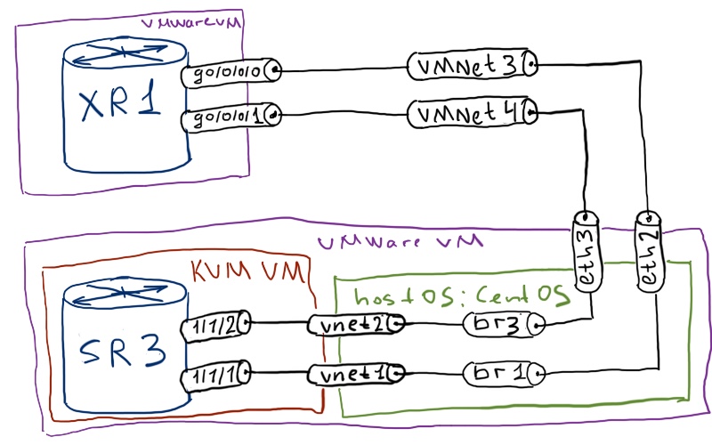
Physical topology remains the same for more than 10 labs already:
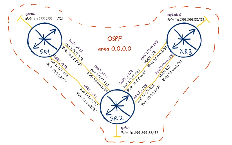
The logical topology is a little bit new. From the real world point of view, it makes no sense as we have single point of failure (SPOF) that is SR2. But we can imagine that there are two paths, which go through different P:
As IGP we use OSPF in our lab. For sure you can use ISIS, it’s up to you. But we have used ISIS previously in L2VPN’s labs, so this time I’m gonna using OSPF. For MPLS forwarding plane we will use MPLS LSPs built by RSVP-TE. There will be two tunnels in each direction for load balancing purposes.
Initial configuration for the lab is in the following files: linux_initialxr3_initialsr2_initialsr1_initial
MPLS forwarding plane
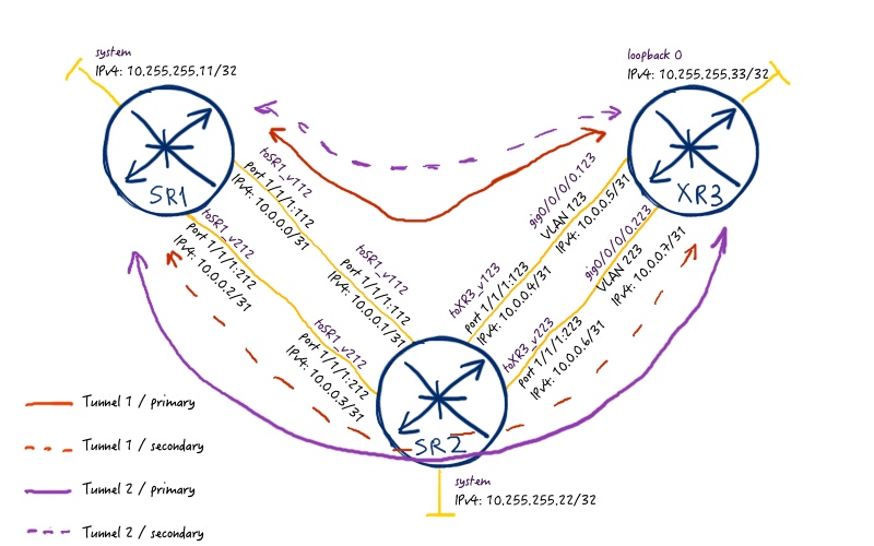
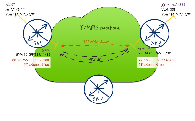
First of all let’s configure MPLS data plane for future BGP/MPLS IP VPN service. Take a look at the following picture:
So we have to two tunnels in each direction between PE routers. They are built in the following ways:
First tunnel between PEs goes only through links with admin-group (affinity) with value of 0x1 (include ZERO).
Its secondary path (standby for Nokia (Alcatel-Lucent) SR OS) avoids these links (exclude ZERO).
Second tunnel between PEs goes only through links with admin-group (affinity) with value of 0x2 (include ONE).
Its secondary path (standby for Nokia (Alcatel-Lucent) SR OS) avoids these links (exclude ZERO).
The configuration is done only at PE routers:
Nokia (Alcatel-Lucent) VSR (SR 7750)
Cisco IOS XR (ASR 9000)
SR1
XR3
A:SR1>edit-cfg# candidate view
—————————
configure
router
mpls
path “ONE_PATH”
no shutdown
exit
path “ANOTHER_PATH”
no shutdown
exit
lsp “SR1_to_XR3_1x”
to 10.255.255.33
cspf
least-fill
primary “ONE_PATH”
include “ZERO”
bandwidth 111
exit
secondary “ANOTHER_PATH”
exclude “ZERO”
bandwidth 111
standby
exit
no shutdown
exit
lsp “SR1_to_XR3_2x”
to 10.255.255.33
cspf
least-fill
primary “ONE_PATH”
include “ONE”
bandwidth 111
exit
secondary “ANOTHER_PATH”
exclude “ONE”
bandwidth 111
standby
exit
no shutdown
exit
exit
exit
exit
—————————
RP/0/0/CPU0:XR3(config)#show conf
interface tunnel-te33111
ipv4 unnumbered Loopback0
signalled-name XR3_to_SR1_1
signalled-bandwidth 333000
autoroute destination 10.255.255.11
destination 10.255.255.11
record-route
path-option 10 dynamic attribute-set ZERO
path-option 20 dynamic attribute-set NO_ZERO
!
interface tunnel-te33112
ipv4 unnumbered Loopback0
signalled-name XR3_to_SR1_2
signalled-bandwidth 333000
autoroute destination 10.255.255.11
destination 10.255.255.11
record-route
path-option 10 dynamic attribute-set ONE
path-option 20 dynamic attribute-set NO_ONE
!
mpls traffic-eng
attribute-set path-option ONE
affinity include ONE
!
attribute-set path-option ZERO
affinity include ZERO
!
attribute-set path-option NO_ONE
affinity exclude ONE
!
attribute-set path-option NO_ZERO
affinity exclude ZERO
!
!
end
Let’s briefly check our MPLS LSPs. In Nokia (Alcatel-Lucent) SR OS you should check first of all so called “tunnel-table”, what is the essence of all MPLS LSPs configured at your device:
We see that metric for both LSPs are the same, so they can load balance the traffic then. At Cisco IOS XR you see both LSPs in RIB:
RP/0/0/CPU0:XR3#show route ipv4 10.255.255.11
Routing entry for 10.255.255.11/32
Known via “application”, distance 2, metric 0 (connected)
Installed Oct 20 08:11:38.154 for 00:03:18
Routing Descriptor Blocks
directly connected, via tunnel-te33111
Route metric is 0
directly connected, via tunnel-te33112
Route metric is 0
No advertising protos.
So we see that our MPLS tunnels are up and running and we can go further to the configuration of BGP/MPLS IP VPN itself.
For more details regarding LSP check refer to the MPLS/RSVP-TE article (link).
BGP/MPLS IPv4 VPN
Now we have approached the core topic of the article that is configuration of the VPN itself. The service map for our article is the following:
The configuration of VPN is necessary only at PE side, so we configure only SR1 and XR3:
Nokia (Alcatel-Lucent) VSR (SR 7750)
Cisco IOS XR (ASR 9000)
SR1
XR3
A:SR1>edit-cfg# candidate view
—————————
configure
router
autonomous-system 65000
bgp
group “IBGP-VPNV4”
peer-as 65000
local-address “10.255.255.11”
family vpn-ipv4
next-hop-self
neighbor “10.255.255.33”
exit
exit
exit
exit
port “1/1/2”
ethernet
mode access
encap-type dot1q
exit
no shutdown
exit
service
customer 2 create
description “CUST_65100”
exit
vprn “65100” customer 2 create
route-distinguisher “10.255.255.11:65100”
auto-bind-tunnel
resolution-filter
rsvp
exit
resolution filter
exit
vrf-target “target:65000:65100”
autonomous-system 65000
interface “toCUST” create
address “192.168.0.0/31”
sap “1/1/2:111” create
exit
no shutdown
exit
bgp
group “CUSTOMER”
family ipv4
exit
exit
no shutdown
exit
exit
exit
—————————
Both in Nokia (Alcatel-Lucent) SR OS and Cisco IOS XR we create first of all BGP peering for the address family VPNV4 (AFI/SAFI 1/128), because it’s basis for our IP VPN service. Then in Nokia (Alcatel-Lucent) SR OS we configure client’s port in access mode in order to be able to create SAP in VRF. Afterwards we create service VPRN 65100 (actually, VRF), where we configure corresponding route-distinguisher (RD) and route-target (RT), as well as interface to customer and customer’s BGP process.
In Cisco IOS XR we configure VRF and RTs in the global configuration context. Then we configure customer’s interface and associate it with VRF. The last step is the configuration of the BGP for this VRF including RD inside global BGP context.
If the logging is enabled, you will see in CLI the following messages, which inform you that BGP peering is built:
SR OS:
2016/11/10 20:21:43.54 UTC MINOR: BGP #2038 Base Peer 1: 10.255.255.33
“VR 1: Group IBGP-VPNV4: Peer 10.255.255.33: moved into established state”
!
!
IOS XR:
RP/0/0/CPU0:Oct 20 09:58:22.455 : bgp[1053]: %ROUTING-BGP-5-ADJCHANGE_DETAIL : neighbor 10.255.255.11 Up (VRF: default; AFI/SAFI: 1/128) (AS: 65000)
As we don’t announce any routes still, we won’t see any prefixes in VRFs/VPRNs. We could announce interconnect prefixes, but usually it isn’t necessary in real deployment, so we don’t do it. What is possible to check at this stage is the peering of BGP in the corresponding address-family. From Nokia (Alcatel-Lucent) SR OS you do it as follows:
It is also worth to check the router-distinguishers and route-targets associated with VPRN/VRF as this ensures you will have correct import/export of routes, when they will be announced. Here is the example from Nokia (Alcatel-Lucent) VSR (SR 7750):
A:SR1# show service service-using
============================================================================
Services
============================================================================
ServiceId Type Adm Opr CustomerId Service Name
—————————————————————————- 65100 VPRN Up Up 2
2147483648 IES Up Down 1 _tmnx_InternalIesService
2147483649 intVpls Up Down 1 _tmnx_InternalVplsService
—————————————————————————-
Matching Services : 3
—————————————————————————-
============================================================================
!
!
A:SR1# show service id 65100 base
============================================================================
Service Basic Information
============================================================================ Service Id : 65100 Vpn Id : 0
Service Type : VPRN
Name : (Not Specified)
Description : (Not Specified)
Customer Id : 2 Creation Origin : manual
Last Status Change: 11/13/2016 11:53:07
Last Mgmt Change : 11/13/2016 11:53:07 Admin State : Up Oper State : Up
— Route Dist. : 10.255.255.11:65100 VPRN Type : regular Oper Route Dist : 10.255.255.11:65100
Oper RD Type : configured AS Number : 65000 Router Id : 10.255.255.11 ECMP : Enabled ECMP Max Routes : 1
Max IPv4 Routes : No Limit
— Auto Bind Tunnel Resolution : filter Filter Protocol : rsvp
—
Max IPv6 Routes : No Limit
Ignore NH Metric : Disabled
Hash Label : Disabled
Entropy Label : Disabled Vrf Target : target:65000:65100
Vrf Import : None
Vrf Export : None
MVPN Vrf Target : None
MVPN Vrf Import : None
MVPN Vrf Export : None
Car. Sup C-VPN : Disabled Label mode : vrf
BGP VPN Backup : Disabled
BGP Export Inactv : Disabled
SAP Count : 1 SDP Bind Count : 0
VSD Domain : <none>
—————————————————————————-
Service Access & Destination Points
—————————————————————————-
Identifier Type AdmMTU OprMTU Adm Opr
—————————————————————————-
sap:1/1/2:111 q-tag 1518 1518 Up Up
============================================================================
At Cisco IOS XRv (ASR 9000) you would use the following commands:
RP/0/0/CPU0:XR3#show vrf CUST_65100 detail VRF CUST_65100; RD 10.255.255.33:65100; VPN ID not set
VRF mode: Regular
Description not set Interfaces: GigabitEthernet0/0/0/0.333 Address family IPV4 Unicast Import VPN route-target communities: RT:65000:65100 Export VPN route-target communities: RT:65000:65100
No import route policy
No export route policy
Address family IPV6 Unicast
No import VPN route-target communities
No export VPN route-target communities
No import route policy
No export route policy
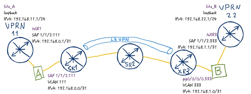
Let’s add the life to our networks in terms of customer. Here is the topology of BGP/MPLS IP VPN service from the customer point of view:
We are going to emulate customers using two VPRN instances at SR2.
Here you can find the final configuration files:
Nokia (Alcatel-Lucent) VSR (SR 7750)
Cisco IOS XR (ASR 9000)
SR1
XR1
A:SR1>edit-cfg# candidate view
————————–
configure
router
policy-option
begin
policy-statement RP_BGP_VPN
default reject
entry 10
from
protocol bgp-vpn
exit
to
protocol bgp
exit
action accept
exit
exit
exit
commit
exit
exit
service
vprn 65100
bgp
group “CUSTOMER”
export RP_BGP_VPN
as-override
peer-as 65100
neighbor 192.168.0.1
exit
exit
exit
exit
exit
exit
—————————
A:SR2>edit-cfg# candidate view
—————————
configure
port 1/1/2
ethernet
mode access
encap-type dot1q
exit
no shutdown
exit
router
policy-option
begin
prefix-list PL_AS65100_11
prefix 192.168.11.0/24
exit
policy-statement RP_AS65100_11
default reject
entry 10
from
protocol direct
prefix PL_AS65100_11
exit
action accept
exit
exit
exit
commit
exit
exit
service
customer 2 create
description CUST_65100
exit
vprn 11 customer 2 create
description Site_A
route-distinguisher 10.255.255.22:11
interface toSR1 create
address 192.168.0.1/31
sap 1/1/2:111 create
exit
no shutdown
exit
interface Site_A create
address 192.168.11.1/24
loopback
no shutdown
exit
autonomous-system 65100
router-id 192.168.11.1
bgp
group eBGP_VPN
export RP_AS65100_11
peer-as 65000
neighbor 192.168.0.0
exit
exit
no shutdown
exit
no shutdown
exit
exit
exit
—————————
A:SR2>edit-cfg# candidate view
—————————
configure
port 1/1/2
ethernet
mode access
encap-type dot1q
exit
no shutdown
exit
router
policy-option
begin
prefix-list PL_AS65100_22
prefix 192.168.22.0/24
exit
policy-statement RP_AS65100_22
default reject
entry 10
from
protocol direct
prefix PL_AS65100_22
exit
action accept
exit
exit
exit
commit
exit
exit
service
customer 2 create
description CUST_65100
exit
vprn 22 customer 2 create
description Site_B
route-distinguisher 10.255.255.22:22
interface toXR3 create
address 192.168.1.1/31
sap 1/1/2:333 create
exit
no shutdown
exit
interface Site_B create
address 192.168.22.1/24
loopback
no shutdown
exit
autonomous-system 65100
router-id 192.168.22.1
bgp
group eBGP_VPN
export RP_AS65100_22
peer-as 65000
neighbor 192.168.1.0
exit
exit
exit
no shutdown
exit
no shutdown
exit
exit
—————————
Linux – bridge A
Linux – bridge B
[root@localhost ~]#
/sbin/vconfig add eth2 333
/sbin/vconfig add vnet6 333
ifconfig eth2.333 up
ifconfig vnet6.333 up
brctl addbr br333
brctl addif br333 eth2.333
brctl addif br333 vnet6.333
ifconfig br333 up
[root@localhost ~]#
/sbin/vconfig add vnet6 111
/sbin/vconfig add vnet2 111
ifconfig vnet6.111 up
ifconfig vnet2.111 up
brctl addbr br111
brctl addif br111 vnet6.111
brctl addif br111 vnet2.111
ifconfig br111 up
At customer routers (VPRN 11 and 22) we just configure local attached interface (emulated by loopback) that is announced via BGP. Remember that we have to configure explicit export policy in Nokia (Alcatel-Lucent) SR OS in BGP in order to announce any route. If you don’t configure them, no single prefix will be advertised. You see that configuration at VPRN 11 and 22 is almost identical.
In order to bring VPRN up you need to define route-distinguisher inside VPRN even in VRF-lite scenario in Nokia (Alcatel-Lucent) SR OS.
At our PE routers we just add specific route policies and BGP peering to the customer. In Nokia (Alcatel-Lucent) SR OS we add policy that allows redistribution of routes learned from MP-BGP to BGP session to customer. In Cisco IOS XR we need policy to allow advertisement routes to eBGP neighbor (by default Cisco IOS XR doesn’t send any routes to eBGP peers). Receiving policy isn’t obligation, but it should be configured as well.
Now we can check routing table at all our devices related to this particular BGP/MPLS IP VPN service. Let’s start with VPRN 11 (SR2) as first CE:
A:SR2# show router 11 route-table
============================================================================
Route Table (Service: 11)
============================================================================
Dest Prefix[Flags] Type Proto Age Pref
Next Hop[Interface Name] Metric
—————————————————————————-
192.168.0.0/31 Local Local 00h57m56s 0
toSR1 0
192.168.11.0/24 Local Local 00h58m07s 0
Site_A 0
192.168.22.0/24 Remote BGP 00h49m48s 170
192.168.0.0 0
—————————————————————————-
No. of Routes: 3
============================================================================
The next device in the flow (regarding to the provided image above) is the first PE that is SR1:
A:SR1# show router 65100 route-table
============================================================================
Route Table (Service: 65100)
============================================================================
Dest Prefix[Flags] Type Proto Age Pref
Next Hop[Interface Name] Metric
—————————————————————————-
192.168.0.0/31 Local Local 02h53m17s 0
toCUST 0
192.168.11.0/24 Remote BGP 00h59m48s 170
192.168.0.1 0
192.168.22.0/24 Remote BGP VPN 00h48m00s 170
10.255.255.33 (tunneled:RSVP:1) 0
—————————————————————————-
No. of Routes: 3
============================================================================
Then comes the second PE XR3:
RP/0/0/CPU0:XR3#show route vrf CUST_65100 ipv4
Codes: C – connected, S – static, R – RIP, B – BGP, (>) – Diversion path
D – EIGRP, EX – EIGRP external, O – OSPF, IA – OSPF inter area
N1 – OSPF NSSA external type 1, N2 – OSPF NSSA external type 2
E1 – OSPF external type 1, E2 – OSPF external type 2, E – EGP
i – ISIS, L1 – IS-IS level-1, L2 – IS-IS level-2
ia – IS-IS inter area, su – IS-IS summary null, * – candidate default
U – per-user static route, o – ODR, L – local, G – DAGR, l – LISP
A – access/subscriber, a – Application route
M – mobile route, r – RPL, (!) – FRR Backup path
Gateway of last resort is not set
B 192.168.0.0/31 [200/0] via 10.255.255.11 (nexthop in vrf default), 00:56:22
C 192.168.1.0/31 is directly connected, 01:40:55, GigabitEthernet0/0/0/0.333
L 192.168.1.0/32 is directly connected, 01:40:55, GigabitEthernet0/0/0/0.333
B 192.168.11.0/24 [200/0] via 10.255.255.11 (nexthop in vrf default), 00:56:22
B 192.168.22.0/24 [20/0] via 192.168.1.1, 00:56:42
And finally we comes to the second CE routers, which we have at VPRN 22 (SR2):
A:SR2# show router 22 route-table
============================================================================
Route Table (Service: 22)
============================================================================
Dest Prefix[Flags] Type Proto Age Pref
Next Hop[Interface Name] Metric
—————————————————————————-
192.168.0.0/31 Remote BGP 00h57m55s 170
192.168.1.0 0
192.168.1.0/31 Local Local 00h58m50s 0
toSR1 0
192.168.11.0/24 Remote BGP 00h57m55s 170
192.168.1.0 0
192.168.22.0/24 Local Local 00h59m01s 0
Site_B 0
—————————————————————————-
No. of Routes: 4
============================================================================
We see that our client’s prefixes from site A and B are installed in all corresponding routing tables along the path. At Nokia (Alcatel-Lucent) VSR SR2 that is one of the PEs you see that prefixes from Site B is available through MPLS LSP build by RSVP-TE. At Cisco IOS XRv XR3 that is another PE you see that prefix from Site A is known via BGP and is available through next hop in default routing table.
The next step is to check which service labels BGP has signaled for this VPN. In Nokia (Alcatel-Lucent) we have to issue two commands to check it:
A:SR1# show router bgp routes vpn-ipv4
============================================================================
BGP Router ID:10.255.255.11 AS:65000 Local AS:65000
============================================================================
Legend –
Status codes : u – used, s – suppressed, h – history, d – decayed, * – valid
l – leaked, x – stale, > – best, b – backup, p – purge
Origin codes : i – IGP, e – EGP, ? – incomplete
===========================================================================
BGP VPN-IPv4 Routes
============================================================================
Flag Network LocalPref MED
Nexthop (Router) Path-Id Label
As-Path
—————————————————————————-
u*>i 10.255.255.33:65100:192.168.22.0/24 100 None
10.255.255.33 None 24004
65100
—————————————————————————-
Routes : 1
============================================================================
!
!
A:SR1# show router bgp neighbor 10.255.255.33 advertised-routes vpn-ipv4
============================================================================
BGP Router ID:10.255.255.11 AS:65000 Local AS:65000
============================================================================
Legend –
Status codes : u – used, s – suppressed, h – history, d – decayed, * – valid
l – leaked, x – stale, > – best, b – backup, p – purge
Origin codes : i – IGP, e – EGP, ? – incomplete
============================================================================
BGP VPN-IPv4 Routes
============================================================================
Flag Network LocalPref MED
Nexthop (Router) Path-Id Label
As-Path
—————————————————————————-
i 10.255.255.11:65100:192.168.0.0/31 100 None
10.255.255.11 None 262143
No As-Path
i 10.255.255.11:65100:192.168.11.0/24 100 None
10.255.255.11 None 262143
65100
—————————————————————————-
Routes : 2
============================================================================
In Cisco IOS XR you just issue one command and that’s it:
RP/0/0/CPU0:XR3#show bgp vpnv4 unicast vrf CUST_65100 labels
Status codes: s suppressed, d damped, h history, * valid, > best
i – internal, r RIB-failure, S stale, N Nexthop-discard
Origin codes: i – IGP, e – EGP, ? – incomplete
Network Next Hop Rcvd Label Local Label
Route Distinguisher: 10.255.255.33:65100 (default for vrf CUST_65100)
*>i192.168.0.0/31 10.255.255.11 262143 nolabel
*>i192.168.11.0/24 10.255.255.11 262143 nolabel
*> 192.168.22.0/24 192.168.1.1 nolabel 24004
Processed 3 prefixes, 3 paths
You might spot that though we haven’t announces explicitly interconnect prefix between SR1 and VPRN 11 at SR2, we see it in BGP RIB at opposite router. This is the default behavior of Nokia (Alcatel-Lucent) SR OS, so you have to care of it.
Now it’s time to make some tests. Let’s perform ping from Customer’s Site A subnet to Site B subnet:
A:SR2# ping router 11 192.168.22.1 source 192.168.11.1 count 1
PING 192.168.22.1 56 data bytes
64 bytes from 192.168.22.1: icmp_seq=1 ttl=61 time=14.6ms.
—- 192.168.22.1 PING Statistics —-
1 packet transmitted, 1 packet received, 0.00% packet loss
round-trip min = 14.6ms, avg = 14.6ms, max = 14.6ms, stddev = 0.000ms
A:SR2#
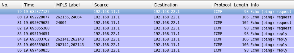
Here what shows us Wireshark at the path:
On the forward path from VPRN 11 to VPRN 22 you see PHP operation that is default for Cisco IOS XR (and other Cisco operation system). This PHP means that SR2 pops the transport label and sends the packet only with service label to XR3. In Nokia (Alcatel-Lucent) SR OS we don’t have such default behavior, so you see transport labels at both hops in MPLS core.
For more information about PHP and it’s configuration in Nokia (Alcatel-Lucent) SR OS and Cisco IOS XR refer to the corresponding article.
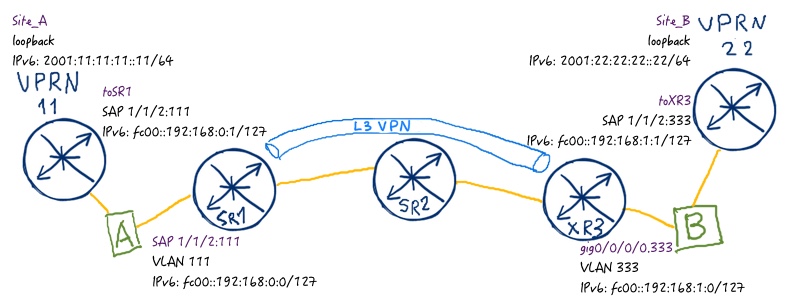
BGP/MPLS IPv6 VPN
So far, so good. We have successfully implemented IP VPN service for IPv4 and we are going to do the same for IPv6. Such implementation is also often called 6VPE. Take a look at the image of the service:
We won’t split configuration part for customer and core part here and will configure everything simultaneously. We use the same links for CE-PE peering, so there is no necessity to make additional configuration at linux:
Nokia (Alcatel-Lucent) VSR (SR 7750)
Cisco IOS XR (ASR 9000)
SR1
XR1
A:SR1>edit-cfg# candidate view
—————————
configure
router
bgp
group “IBGP-VPNV4”
family vpn-ipv4 vpn-ipv6
exit
exit
exit
service
vprn 65100
interface “toCUST”
ipv6
address fc00::192:168:0:0/127
link-local fe80::7750:51:111:1
exit
exit
bgp
group “CUSTOMER”
neighbor fc00::192:168:0:1
family ipv6
exit
exit
exit
exit
exit
exit
—————————
A:SR2>edit-cfg# candidate view
—————————
configure
router
policy-option
begin
prefix-list PL_IPV6_AS65100_11
prefix 2001:11:11:11::/64
exit
policy-statement RP_AS65100_11
entry 20
from
protocol direct
prefix PL_IPV6_AS65100_11
exit
action accept
exit
exit
exit
commit
exit
exit
service
vprn 11
interface toSR1 create
ipv6
address fc00::192:168:0:1/127
link-local fe80::7750:53:111:1
exit
exit
interface Site_A create
ipv6
address 2001:11:11:11::11/64
exit
exit
bgp
group eBGP_VPN
neighbor fc00::192:168:0:0
family ipv6
exit
exit
no shutdown
exit
no shutdown
exit
exit
exit
—————————
A:SR2>edit-cfg# candidate view
—————————
configure
router
policy-option
begin
prefix-list PL_IPV6_AS65100_22
prefix 2001:22:22:22::/64
exit
policy-statement RP_AS65100_22
entry 20
from
protocol direct
prefix PL_IPV6_AS65100_22
exit
action accept
exit
exit
exit
commit
exit
exit
service
vprn 22
interface toXR3 create
ipv6
address fc00::192:168:1:1/127
link-local fe80::7750:53:333:1
exit
exit
interface Site_A create
ipv6
address 2001:22:22:22::22/64
exit
exit
bgp
group eBGP_VPN
neighbor fc00::192:168:1:0
family ipv6
exit
exit
no shutdown
exit
no shutdown
exit
exit
exit
—————————
In SR1 we don’t configure and apply new route-policy as it’s already attached during configuration of IPv4 part.
At PE routers we add vpnv6 unicast address-family at the peering between SR1 and XR3. Pay attention that in Nokia (Alcatel-Lucent) SR OS you have to mention all previous address families if you want to retain them, otherwise they will be deleted. In Cisco IOS XR you just configure new entity inside neighbor context. We also add IPv6 addresses at interfaces and configure BGP peering inside VRF/VPRN to IPv6 CE. In Cisco IOS XR we also add support of IPv6 unicast address family to VRF. In Nokia (Alcatel-Lucent) SR OS it’s done automatically.
At CE routers we just configure IPv6 addresses and add new entry into BGP policy in order to announce IPv6 prefixes.
Let’s check BGP peering and route table in VPRN 11 at SR2 that is Nokia (Alcatel-Lucent) VSR emulating CE:
A:SR2# show router 11 bgp summary
============================================================================
BGP Summary
============================================================================
Legend : D – Dynamic Neighbor
============================================================================
Neighbor
Description
AS PktRcvd InQ Up/Down State|Rcv/Act/Sent (Addr Family)
PktSent OutQ
—————————————————————————-
192.168.0.0
65000 117 0 00h55m05s 1/1/1 (IPv4)
115 0
fc00::192:168:0:0
65000 77 0 00h21m51s 1/1/1 (IPv6)
107 0
—————————————————————————-
!
!
A:SR2# show router 11 route-table ipv6
============================================================================
IPv6 Route Table (Service: 11)
============================================================================
Dest Prefix[Flags] Type Proto Age Pref
Next Hop[Interface Name] Metric
—————————————————————————-
2001:11:11:11::/64 Local Local 00h30m53s 0
Site_A 0
2001:22:22:22::/64 Remote BGP 00h19m05s 170
fc00::192:168:0:0 0
fc00::192:168:0:0/127 Local Local 00h30m53s 0
toSR1 0
—————————————————————————-
No. of Routes: 3
============================================================================
As we have built two separate BGP sessions, we see both of them in “BGP summary”. In the route table you see that next hop for site B prefix is resolved to global unicast address (actually, site scope) prefix.
At first PE that is Nokia (Alcatel-Lucent) VSR SR1 router we’ll check BGP peering for core part in addition to route-table:
A:SR1# show router 65100 route-table ipv6
============================================================================
IPv6 Route Table (Service: 65100)
============================================================================
Dest Prefix[Flags] Type Proto Age Pref
Next Hop[Interface Name] Metric
—————————————————————————-
2001:11:11:11::/64 Remote BGP 00h33m19s 170
fc00::192:168:0:1 0
2001:22:22:22::/64 Remote BGP VPN 00h30m33s 170
10.255.255.33 (tunneled:RSVP:1) 0
fc00::192:168:0:0/127 Local Local 01h00m25s 0
toCUST 0
—————————————————————————-
No. of Routes: 3
Flags: n = Number of times nexthop is repeated
============================================================================
!
!
A:SR1# show router bgp summary
============================================================================
BGP Summary
============================================================================
Legend : D – Dynamic Neighbor
============================================================================
Neighbor
Description
AS PktRcvd InQ Up/Down State|Rcv/Act/Sent (Addr Family)
PktSent OutQ
—————————————————————————-
10.255.255.33
65000 147 0 00h56m26s 1/1/2 (VpnIPv4)
131 0 1/1/2 (VpnIPv6)
—————————————————————————-
Here you see that we have only on BGP session for both address families (vpnv4 and vpnv6 unicast that is 1/128 and 2/128). It means that next hop lookup is the same for both address families and it’s resolved to MPLS LSP build by RSVP-TE. Let’s check BGP RIB as well (remember, we see here only received routes):
A:SR1# show router bgp routes vpn-ipv6
============================================================================
BGP Router ID:10.255.255.11 AS:65000 Local AS:65000
============================================================================
Legend –
Status codes : u – used, s – suppressed, h – history, d – decayed, * – valid
l – leaked, x – stale, > – best, b – backup, p – purge
Origin codes : i – IGP, e – EGP, ? – incomplete
============================================================================
BGP VPN-IPv6 Routes
============================================================================
Flag Network LocalPref MED
Nexthop (Router) Path-Id Label
As-Path
—————————————————————————-
u*>i 10.255.255.33:65100:2001:22:22:22::/64 100 None ::ffff:10.255.255.33 None 24008
65100
—————————————————————————-
Routes : 1
============================================================================
At Cisco IOS XRv PE that is our XR3 we see the same information but displayed in the different way:
We see advertised and received prefixes for both address families. Actually their amount is the same as we configure the same policies. I guess you might be interesting in what we see in the routing table and BGP RIB:
RP/0/0/CPU0:XR3#show bgp vpnv6 uni vrf CUST_65100
Status codes: s suppressed, d damped, h history, * valid, > best
i – internal, r RIB-failure, S stale, N Nexthop-discard
Origin codes: i – IGP, e – EGP, ? – incomplete
Network Next Hop Metric LocPrf Weight Path
Route Distinguisher: 10.255.255.33:65100 (default for vrf CUST_65100)
*>i2001:11:11:11::/64 10.255.255.11 100 0 65100 i
*> 2001:22:22:22::/64 fc00::192:168:1:1
0 65100 i
*>ifc00::192:168:0:0/127
10.255.255.11 100 0 i
Processed 3 prefixes, 3 paths
!
!
RP/0/0/CPU0:XR3#show route vrf CUST_65100 ipv6
Codes: C – connected, S – static, R – RIP, B – BGP, (>) – Diversion path
D – EIGRP, EX – EIGRP external, O – OSPF, IA – OSPF inter area
N1 – OSPF NSSA external type 1, N2 – OSPF NSSA external type 2
E1 – OSPF external type 1, E2 – OSPF external type 2, E – EGP
i – ISIS, L1 – IS-IS level-1, L2 – IS-IS level-2
ia – IS-IS inter area, su – IS-IS summary null, * – candidate default
U – per-user static route, o – ODR, L – local, G – DAGR, l – LISP
A – access/subscriber, a – Application route
M – mobile route, r – RPL, (!) – FRR Backup path
Gateway of last resort is not set
B 2001:11:11:11::/64
[200/0] via ::ffff:10.255.255.11 (nexthop in vrf default), 00:45:19
B 2001:22:22:22::/64
[20/0] via fc00::192:168:1:1, 00:42:51
B fc00::192:168:0:0/127
[200/0] via ::ffff:10.255.255.11 (nexthop in vrf default), 01:03:58
C fc00::192:168:1:0/127 is directly connected,
01:06:47, GigabitEthernet0/0/0/0.333
L fc00::192:168:1:0/128 is directly connected,
01:06:47, GigabitEthernet0/0/0/0.333
The next hop of the routes known from SR1 is “::ffff:10.255.255.11” and learned from default vrf. This is form of IPv4 address that you will always see, when IPv6 route is available over MPLS VPN.
Finally we check the routing table at VPRN 22 (SR2 CE):
A:SR2# show router 22 route-table ipv6
============================================================================
IPv6 Route Table (Service: 22)
============================================================================
Dest Prefix[Flags] Type Proto Age Pref
Next Hop[Interface Name] Metric
—————————————————————————-
2001:11:11:11::/64 Remote BGP 00h47m09s 170
fc00::192:168:1:0 0
2001:22:22:22::/64 Local Local 00h48m59s 0
Site_B 0
fc00::192:168:0:0/127 Remote BGP 00h47m09s 170
fc00::192:168:1:0 0
fc00::192:168:1:0/127 Local Local 00h47m54s 0
toXR3 0
—————————————————————————-
No. of Routes: 4
============================================================================
So far we have made a brief review of our tables and now we’ll perform the same ping test as we’ve done previously but this time for IPv6:
A:SR2# ping router 11 2001:22:22:22::22 source 2001:11:11:11::11 count 1
PING 2001:22:22:22::22 56 data bytes
64 bytes from 2001:22:22:22::22 icmp_seq=1 hlim=61 time=24.3ms.
—- 2001:22:22:22::22 PING Statistics —-
1 packet transmitted, 1 packet received, 0.00% packet loss
round-trip min = 24.3ms, avg = 24.3ms, max = 24.3ms, stddev = 0.000ms
A:SR2# admin save
Writing configuration to cf3:\config.cfg
Saving configuration … OK
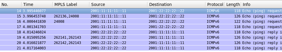
Wireshark shows us almost the same picture as above:
The only difference you might spot is that Cisco IOS XR allocates separate labels for IPv4 and IPv6 prefixes, whereas Nokia (Alcatel-Lucent) SR OS creates just one label for all prefixes associates with particular VPRN by default.
During configuration of this lab I’ve faced very strange behavior of Nokia (Alcatel-Lucent) VSR, when newly configured BGP processes in VPRNs 11 and 22 weren’t sending any BGP packets so BGP peering with PE wasn’t established. I’ve tried to make some reconfiguration but there was no success. Then I’ve restarted that VSR and everything started working as proper. As Germanys say “Reboot tut gut”, what means in English “reboot makes good”.
Conclusion
Comparing to the MPLS L2VPN services, configuration of MPLS L3 VPN (BGP/MPLS IP VPN) is much simpler and shorter. Basically you need only route distinguishers and route targets, which were necessary in all BGP-based L2 VPN services as well. All features, which we have reviewed from the beginning of our journey into joint operation of Nokia (Alcatel-Lucent) SR OS / Cisco IOS XR world, allows us to build middle-size network for service provider. In the next articles we’ll discover some advanced features that help you to build high scalable network. Take care and good bye!