

Hello my friend,
I’m starting the next interesting part of my journey in land of Nokia (Alcatel-Lucent) and Cisco IOS XR. In this and a couple of next series we’ll talk about MPLS L2 VPN services. The easiest one is VPWS (Virtual Pseudo Wire Service) and we’ll review two its types: LDP-based and BGP-based.
Disclaimer
As usually I hope that you know basic of VPWS. If not, refer to some learning materials and/or courses. The good examples are “Nokia Service Architecture SRC course” and book “MPLS in the SDN Era”.
Brief overview
VPWS has a lot of other names. In Nokia (Alcatel-Lucent) SR OS it’s called “x”pipe, where “x” represent type of traffic being transported, like epipe – Ethernet VPWS, cpipe – CESoPSN VPWS and etc. Cisco world has another marvelous name AToM, what stands for Any Transport over MPLS. There are also a lot of other abbreviations like PW (PseudoWire), PWE3 (PseudoWire End-to-End Emulation), E-line (MEF description), VLL (virtual Leased Line) and so on.
Regardless of the term used, in nutshell VPWS is just encapsulation of L2 PDU (protocol data unit, i.E. frame for Ethernet) coming from one device into MPLS labeled frame, transfer this MPLS frame over MPLS cloud and decapsulation from MPLS back to original L2PDU at another side of MPLS cloud. Usually the original structure of L2 PDU including L2 header is preserved, so two hosts on different sides of the VPWS will have L2 adjacency with each other. “Usually” means that in certain cases there might be no L2 adjacency, if we implement interworking, what means connection of two different media types (Ethernet and TDM, for example) on two ends of the same pseudowire.
What are we going to test?
As I’ve mentioned in the very beginning there are two type of signaling for VPWS. The first one is LDP-based and described in RFC4447. This type is called “Martini” VPWS by the name of one of the authors, whose name is Luca Martini. The second type of VPWS is BGP-based and described in RFC6624. The type is called “Kompella” VPWS by the name of the author, whose name Kireeti Kompella. I provide these names, because quite often you can see in the different forums or articles referring to “Martini” or “Kompella” L2 VPN.
Topology
In the recent article (link) I was considering of changing the physical topology. The reason for that was my ongoing test of openvswitch (link), which I have installed instead of ordinary linux bridge. Unfortunately there are some problems with its operation, which lead to sporadic packet drop. This problem isn’t visible, when I test lab infrastructure with ping, but ISIS adjacency flaps each 2-5 minutes. That’s why I decided to use further topology that I’ve used before:
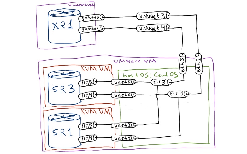

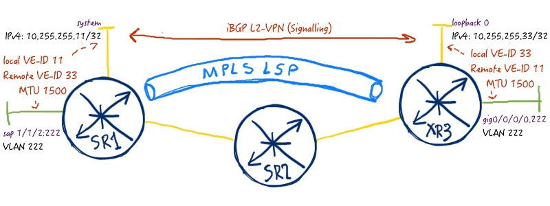
You can point out that devices’ names are a little bit different at the picture above. Besides hostnames I’ve changed IP addressing scheme as well. In my opinion, these changes makes configuration and its tracking easier. The resulting logical topology is the following:
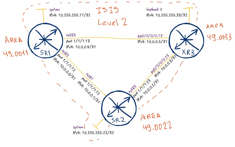
Let’s briefly discussed devices role and what is configured. Routers SR1 and XR3 are PE (provider edge) routers, and SR2 is P (provider core) router. It means that all kind of services (i.e. L2/L3 MPLS VPNs) we’ll configure between SR1 and XR3. As routing protocol (IGP) we’ll use ISIS in this lab. MPLS forwarding plane will be formed by RSVP-TE, so all interfaces between our routers are enabled in MPLS (in Cisco IOS XR MPLS TRAFFIC-ENG) and RSVP contexts. In the same time MPLS LSPs aren’t configured, so it will be part of our configuration. Initial configuration for the lab is in the following files:
Brief overview of MPLS service framework
Configuration of different MPLS-related (and not only) services in Nokia (Alcatel-Lucent) SR OS looks unusual for everyone, who comes from Cisco IOS world. But for those, who have experience with Cisco IOS XR, the difference isn’t so huge, but it still exists.
The common thing for Nokia (Alcatel-Lucent) SR OS and Cisco IOS XR is that configuration is done in specific configuration context. In classical Cisco IOS/ IOS XR the configuration of VPNs is done partially at interface level (sometimes the main part of the config is done at the interface). So Cisco IOS XR is different from Cisco IOS in this question. Nokia (Alcatel-Lucent) SR OS and Cisco IOS XR is very similar in this question.
The main difference between Nokia (Alcatel-Lucent) SR OS and Cisco IOS XR is mapping of the service to transport tunnel (we can also call this process as next-hop lookup).
In Nokia (Alcatel-Lucent) SR OS you have a concept of SDP (Service Distribution Point). SDP is configuration entity that has information about MPLS transport to be used (LDP, SPRING, BGP, RSVP) and signaling (targeted LDP or BGP). After SDP is configured you map different services (VPWSs or VPLSs) to SDP. Another configuration entity is “Customer”. Each service is mapped to a certain (and only one) customer in the time of creation. Each customer can have multiple services mapped to it. So “Customer” is used for administrative and monitoring purposes rather than for technical tasks.
In Cisco IOS XR you have concept of groups (xconnect or bridge), which might be considered as analog of Nokia’s “Customer”. All the configuration regarding service signaling is done into configuration context of each certain service. And mapping of the service to MPLS forwarding plane is done automatically via next-hop lookup process that is common not only for MPLS services but for usual routing as well.
This difference is really crucial to understand. For Cisco IOS XR approach seems to be more logical, as we have common rules for all traffic (or may be it seems to be more logical because I have more experience with Cisco). On the other hand in Nokia (Alcatel-Lucent) SR OS it’s easier to map certain traffic to certain path, what is important for differentiating customers according to SLA (gold, silver, bronze) or just different type of traffic to different paths.
Good explanation of Nokia (Alcatel-Lucent) MPLS service framework is provided in “Nokia Service Architecture SRC course”.
I guess it might be hard to understand words without images above, so let’s go to configuration phase and there you’ll understand it better, I hope.
LDP-based VPWS (Martini)
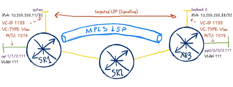
Historically Martini VPWS was developed earlier than Kompella VPWS, so I’ll review it first. Here is the sample service that we want to deploy:

In general we have to pass the following steps (both in Nokia (Alcatel-Lucent) SR OS and Cisco IOS XR) to get LDP-based VPWS running:
- establish MPLS LSP (in case of RSVP-TE we need configure MPLS tunnel);
- configure customer interfaces in appropriate way;
- configure VPWS including creation of signaling session (t-LDP) and align its parameters.
Keep in mind that following parameters must match at both Pes in order VPWS to get up: VC-ID, VC-Type, MTU
Here is configuration to get our service working:
| Nokia (Alcatel-Lucent) VSR (SR 7750) | Cisco IOS XR (ASR 9000) |
| SR1 | XR1 |
|
A:SR1>edit-cfg# candidate view |
RP/0/0/CPU0:XR3(config)#show conf |
I suppose you have question “what we are doing here”, right? Well, the question is fully correct, so let’s discuss, what we are doing here.
In Nokia (Alcatel-Lucent) VSR (SR 7750) we have to configure customer-facing port as “access”. It’s necessary, otherwise you won’t be able to map it to any service. Also point it that we map it to service, we call it SAP “Service Attachment Point”, but technically it’s just the same port. Then we configure MPLS LSP to Cisco IOS XR router XR3 using RSVP-TE.
For more information about configuration of MPLS / RSVP-TE LSP refer to corresponding article.
Pay attention that we enable LDP, but we don’t make any configurations there. T-LDP sessions is established automatically to IPv4 address configured in SDP as “far-end”, when SDP is associated to at least one service and this service is activated. You don’t see any remarks that SDP uses targeted LDP, because it’s default configuration. Further in BGP-based VPWS we’ll change it. Also we map SDP to certain MPLS LSP. Each configuration entity (CUSTOMER, SDP, EPIPE) has a number, which is an arbitrary value. Using SDP number, you map epipe (what is actually VPWS service) to certain MPLS LSP to certain PE. Combination sdp “1:1133” is very important, because it means that you establish T-LDP session to far-end of SDP 1 with VC-ID (or PW-ID) 1133. You can reuse the same SDP for other services with other VC-IDs. Also it’s necessary to configure VC-TYPE as Vlan, otherwise you won’t interoperate with Cisco IOS XR, where Vlan is the only VC-TYPE for VPWS if attached interface is tagged. Though it isn’t necessary, we enable control-word for this VPWS, as it eliminates possibility of out-of-order packets in cases of load balancing (ECMP) in the network.
In Cisco IOS XR there is no specific type of port for different customer services. The only keyword is “l2stranport” upon sub interface creation, what means that switching engine is used. You configure “l2transport” at sub interface in Cisco IOS XR, when you configure VPWS, VPLS, EVPN or just local BVI (bridge virtual interface). Then we configure pseudowire-class (in BGP-based VPWS we’ll configure it in Nokia (Alcatel-Lucent) SR OS as well), where we define usage of control-word. “Xconnect” group is used for configuration of VPWS and certain “p2p” entry is a VPWS itself (epipe in Nokia (Alcatel-Lucent) SR OS). Again, the most important is VC-ID match between SR1 and XR3. Here we map VC-ID directly to neighbor IPv5 address of the neighbor, what creates targeted-LDP session to SR1. We don’t configure VC-TYPE, as it’s already Vlan and is only possible in this case. Pw-class is added to neighbor configuration to be used on VPWS.
Configuration of path-mtu is workaround. It’s configured automatically, but here I change manually just to bring VPWS working. Different MTUs and their interdependency is good explained in “Nokia Service Architecture SRC course”.
Now, after explanation above I assume that you feel yourself more confident with configuration of LDP-based (Martini) VPWS in mixed environment with Nokia (Alcatel-Lucent) SR OS and Cisco IOS XR. Let’s review the output of the most important show commands. The next two are from Nokia (Alcatel-Lucent) VSR (SR7750):
|
A:SR1# show service service-using |
The first command show all configured services and their numbers, whereas the second one displays the basic information about service (including service-MTU) and operational status of the service and its components. Very often you will want to check the detail information about service components, especially if they are operational down to find error description. More often you have problems with LDP-related part of VPWS that is SDP, so here you can see details of SDP in context of this service:
|
A:SR1# show service id 1 sdp 1:1133 detail |
The output above is significantly reduced, and I’ve left only relevant information to our case. As we use targeted LDP (T-LDP) for session signaling, we can check the parameters of this service in LDP:
|
A:SR1# show router ldp bindings services |
You can see that Nokia (Alcatel-Lucent) SR OS and Cisco IOS XR has different set of attributes activated by default. Nevertheless it doesn’t impact operation. The most important is to align VC-ID, VC-TYPE and Service-MTU. Also if you configure control world (as we do in this example), it also must be align, so it must be configured at both sides of VPWS.
What about Cisco IOS XR? It also has a number of useful commands that shows, what is going on with your L2 VPN:
|
RP/0/0/CPU0:XR3#show l2vpn xconnect |
The output above is similar to “show router ldp binding” in Nokia (Alcatel-Lucent) SR OS. There is no SDP in Cisco IOS XR, so as I’ve said the mapping of VPWS to the MPLS LSP is done via next-hop lookup. The next-hop for this service is IPv4 address 10.255.255.11 (SR1), so in the routing table we check that this addess is available through MPLS tunnel built with RSVP-TE:
|
RP/0/0/CPU0:XR3#show route ipv4 10.255.255.11/32 |
The latter command shows the LFIB of XR1, where you can see labels for VPWS service as well.
Cisco IOS XRv doesn’t support forwarding plane for L2VPN, so we can’t make any kind of ping. But positive output of show commands is OK to check service operation.
BGP-based VPWS (Kompella)
The second type of VPWS that you may configure is BGP-based VPWS. Personally I like this type of VPWS more, because you can fully avoid usage of LDP in your network. I don’t say that LDP is bad, LDP is good. But if you can reduce the number of signaling protocols used in the network, it’s worth it. Remember the networking mantra:
The good network design isn’t the one, to which you can’t add something. The good network design is the one, from which you can’t remove anything.
To get BGP-based VPWS working we need to perform the following activities (both in Nokia (Alcatel-Lucent) SR OS and Cisco IOS XR) to get LDP-based VPWS running:
- establish MPLS LSP (in case of RSVP-TE we need configure MPLS tunnel);
- configure customer interfaces in appropriate way;
- configure BGP session for address-family l2vpn vpls-vpws (AFI/SAFI 25/65);
- configure BGP auto discovery parameters at PEs (important: route-targets must match at both ends);
- configure BGP signaling;
So you can see that we have a little bit more steps than in LDP-based VPWS. Also I want you to pay attention to the first step. In the beginning of the article I was talking that in Nokia (Alcatel-Lucent) SR OS we used SDPs for service mapping to MPLS LSP and for signaling. So we need to create new SDP that use BGP as signaling protocol:
In the same time Cisco IOS XR maps traffic to tunnel using next-hop lookup in routing table, so we don’t need to create any new tunnel, if SR1 announces prefixes with BGP NH attribute set to its system interface IPv4 address (10.255.255.11). So to build BGP-based VPWS (Kompella) we implement the following configuration to SR1 and XR3:
| Nokia (Alcatel-Lucent) VSR (SR 7750) | Cisco IOS XR (ASR 9000) |
| SR1 | XR1 |
|
A:SR1>edit-cfg# candidate view |
RP/0/0/CPU0:XR3(config)#show conf |
In Nokia (Alcatel-Lucent) SR OS we configure BGP in corresponding address-family first of all. Then we create new SDP, but pay attentions that MPLS LSP is the same, so we don’t create it again. In order to map BGP-based VPWS to a certain LSP, we create pw-template with “prefer-provisioned-sdp” option, which has configured the same “sdp-group” as SDP itself. Also in pw-template we configure VC-TYPE and other parameters. In the EPIPE context the most important is BGP auto-discovery and BGP-VPWS section. As I’ve said, route-target must be the same at both ends of VPWS, whereas VE-IDs must be mirrored.
In Cisco IOS XR there are two major differences (besides BGP and BGP-related parameters). First of all, the interface is configured in another way. Actually it’s correct way how to configure it and in LDP-based VPWS it also should be configured so, but due to Cisco IOS XRv limitations I’ve configured it in another way. The second difference is that he were configure “mp2mp” service, not “p2p”. VPN-ID is an arbitrary value in this case, because you see, it isn’t configured in Nokia (Alcatel-Lucent) SR OS. It plays crucial role in BGP-based VPLS, but here it isn’t relevant, though it must be configured in Cisco IOS XR.
Also pay attention that here we change service-MTU in Nokia (Aclatel-Lucent) SR OS. Cisco IOS XR treats MTU in LDP-based and BGP-based VPWS in different way.
“Show” must go on! Let’s check the output of the most useful show commands from Nokia (Alcatel-Lucent) SR OS, which are related to our BGP-based VPWS (Kompella):
|
A:SR1# show service id 2 base |
You see that SDP type is “BgpVpws” and VC-ID is automatically generated number, whereas SDP number is “11”, what corresponds to the manually configured one. Now, SDP details:
|
A:SR1# show service id 2 sdp detail |
Also BGP information is very useful for troubleshooting:
|
A:SR1# show service id 2 bgp |
I’m sure, you remember that besides VC-TYPE and VC-ID (in BGP case VE-IDs must match) also Service-MTU mast match. In Martini VPWS we’ve checked LDP to see MTU. Here we have to check announced BGP routes:
|
A:SR1# show router bgp routes l2-vpn detail |
Now it’s Cisco IOS XR turn to show, how BGP-based VPWS works from its point of view:
|
RP/0/0/CPU0:XR3#show l2vpn discovery |
You may see that PW-IDs (or VC-IDs) have different value at SR1 and XR3, though they work well. All BGP information you can check in BGP RIB:
|
RP/0/0/CPU0:XR3#show bgp l2vpn vpws mp2mp CUSTOMER_A:VPWS-BGP |
MTU is announced in the extended community field, so you need to check detail information of interesting routes to figure it out:
|
RP/0/0/CPU0:XR3#show bgp l2vpn vpws mp2mp CUSTOMER_A:VPWS-BGP 11:33/32 | inc Ext |
As I’ve already said in the end of LDP-based VPWS part, Cisco IOS XR has limitations regarding L2VPN data plane. That’s why we can only check control plane (if signaling works correct), but we can’t make any pings, traceroute and so on.
The final configs are here:
Lessons learned
If you have carefully compared the outputs of MTU in different commands, you can spot inconsistency of MTU value. Take a look first of all at Nokia (Alcatel-Lucent) SR OS side:
|
A:SR1# show service id 1 base | match MTU |
Service-MTU in VSR (SR 7750) stands for actual maximum size of L2 packet (including L2 header). You remember, we have configured service-mtu at SR1 in the BGP-based VPWS, and left the default value in LDP-based one. Now it’s time of Cisco IOS XR:
|
RP/0/0/CPU0:XR3#show l2vpn xconnect detail | inc “Group|MPLS|MTU” |
You see that values are the same. Probably this is bug of Cisco IOS XR (or XRv deployment)/ But in the LDP-based VPWS only IP MTU is calculated (1500 bytes = 1514 bytes (Ethernet frame) – 14 bytes (Ethernet header), whereas in BGP-based VPWS 1500 bytes is L2 MTU including Ethernet header.
In order to solve this problem, you should always check what is announced in LDP and BGP messages and check errors, if they exist.
Conclusion
MPLS is very popular technology and number one choice for communication service provider (CSP) networks mainly due to its service’s framework. For sure Traffic Engineering and protection (secondary path or fast reroute) is also important, but the ability to transfer any kind of data (Ethernet, TDM, ATM, IP and so on) over the same network makes MPLS incredible tool. In the example above I’ve used RSVP-TE based LSP, but you can take any other option to build MPLS forwarding plane (LDP, BGP-LU, SPRING). From the service prospective you also have two options, what to use to signal the service (BGP or LDP). Such number of choices gives you high level of flexibility to build VPWS that matches your design and expertise. Take care and good bye!
Support us
BR,
Anton Karneliuk