TI-LFA (with Segment Routing) at Nokia (Alcatel-Lucent) SR OS and Cisco IOS XR
Anton Karneliuk
Hello my friend,
The last article I’ve covered two possible options how you can increase the robustness of your network. It was done via introducing FRR/LFA (Fast Reroute / Loopfree alternative) for pure IPv4/IPv6 addresses and for LDP. Now let’s see the most scalable option – topology independent LFA (TI-LFA) based on SPRING (segment routing).
1 2 3 4 5
No part of this blogpost could be reproduced, stored in a
retrieval system, or transmitted in any form or by any
means, electronic, mechanical or photocopying, recording,
or otherwise, for commercial purposes without the
prior permission of the author.
Disclaimer
I’m starting now to write this article without understanding how to show you operation of TI-LFA at Nokia (Alcatel-Lucent) SR OS router, just because my tests were still not successful. Nevertheless, I hope to find solution till the end of the article. In any case I’m already able to show you Cisco IOS XR part, what is in general sufficient for me to begin.
Brief overview
The discussion that was started in the previous article shew some problems with traditional IP FRR / LFA (IP fast reroute / loopfree alternative) and even remote LFA approach. “Ordinary” LFA has problems of working with loop topologies, therefore its applicability is quite low. Remote LFA provides the mean to overcome it, but it isn’t standardized, what leads to very complex configuration in interoperable scenario. You remember, I had to manually configure RSVP-TE tunnels with explicit hops in order to make remote LFA protection in Nokia (Alcatel-Lucent) SR OS routers. Not very scalable solution at all.
Topology independent loopfree alternative (TI-LFA) is wonderful tool from SPRING (Segment Routing) toolbox that provides us capability to deploy really quick, solid and interoperable mechanism for local restoration. It’s really topology independent, so it suits mesh, ring and fabric topologies.
Though it isn’t obvious in Nokia (Alcatel-Lucent) SR OS at a glance.
All the calculation of primary and protection nodes is done via SPF algorithm, what is essential both for OSPF and ISIS protocols, and the protection is done via label stacking.
What are we going to test?
It’s easier to understand TI-LFA at the example. I’m gonna to show you its operation both in partial-mesh and ring topology for IPv4 addresses for both vendors, which I’m writing about, Nokia (Alcatel-Lucent) and Cisco.
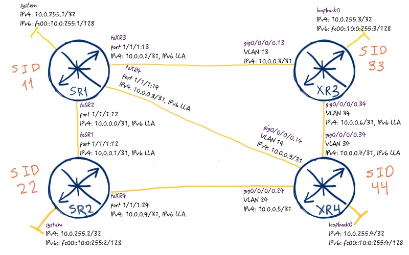
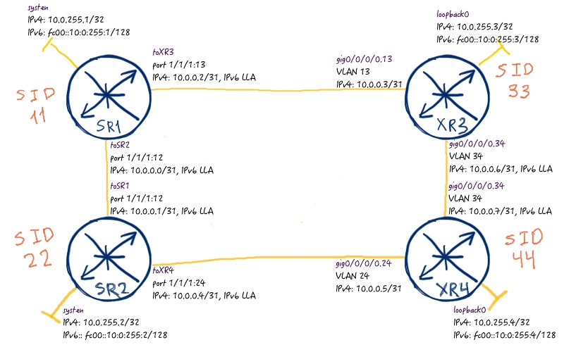
Topology
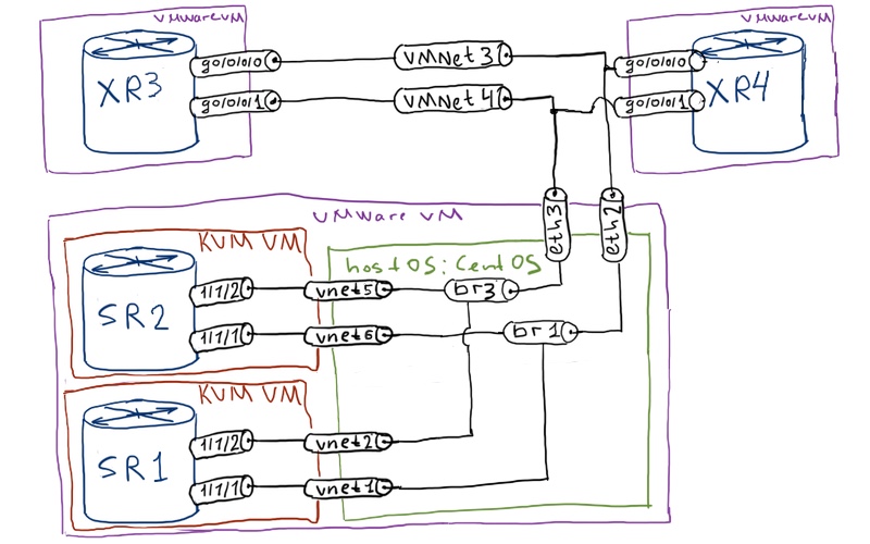
The physical setup of my lab consists of four routers (2x Nokia (Alcatel-Lucent) VSR (virtual SR 7750) and 2x Cisco IOS XRv (virtual ASR 9000)).
This is the default setup for the recent labs, though previously I’ve used only 3 routers due to limitation of my laptop.
Both logical topologies in this article will be just the same as they were in the previous one. The initial topology has a partial mesh architecture:
The routing protocol is ISIS, though you can deploy OSPF if you want. Initial configuration are the same as in the previous article, but for your convenience you can find it here as well: initial_xr4initial_xr3initial_sr2initial_linuxinitial_sr1
Configuration of SPRING (Segment Routing) in Nokia (Alcatel-Lucent) SR OS and Cisco IOS XR
We can check the operation of Segment routing just by looking into LFIB. Let’s take LFIB from SR1, which is Nokia (Alcatel-Lucent) SR OS router, for example:
The interesting point here is that configuration in Nokia (Alcatel-Lucent) SR OS and Cisco IOS XR is done completely at different levels. In Nokia VSR (SR 7750) you just activate remote LFA globally for ISIS, whereas in Cisco IOS XRv (ASR 9000) you configure it only at interface level.
Nokia (Alcatel-Lucent) SR OS has per-interface LFA commands, as well as Cisco IOS XR has global LFA commands, but they are necessary only for fine tuning.
TI-LFA in mesh topology
If you have read my previous article about FRR/LFA for IPv4/IPv6, you already know the commands that are necessary to be used to check state of the backup. If not, it’s not a problem, take a look at the commands below. Nokia (Alcatel-Lucent) SR OS router SR1 can be checked as followed:
We have 100% LFA coverage for all prefixes, meaning that all the prefixes, which can have backup, have it. You remember, we have a partial mesh topology now, so backup next-hop for both protected links are XR4.
Now let’s check Cisco IOS XR router XR4:
RP/0/0/CPU0:XR4#show isis fast-reroute
IS-IS CORE IPv4 Unicast FRR backups
—
Codes: L1 – level 1, L2 – level 2, ia – interarea (leaked into level 1)
. df – level 1 default (closest attached router), su – summary null
. C – connected, S – static, R – RIP, B – BGP, O – OSPF
. E – EIGRP, A – access/subscriber, M – mobile, a – application
. i – IS-IS (redistributed from another instance)
. D – Downstream, LC – Line card disjoint, NP – Node protecting
. P – Primary path, SRLG – SRLG disjoint, TM – Total metric via backup
—
Maximum parallel path count: 8
—
L2 10.0.255.1/32 [10/115]
. via 10.0.0.8, GigabitEthernet0/0/0/0.14, SR1, SRGB Base: 500000, Weight: 0
. FRR backup via 10.0.0.4, GigabitEthernet0/0/0/0.24, SR2, SRGB Base: 500000, Weight: 0, Metric: 20
L2 10.0.255.2/32 [10/115]
. via 10.0.0.4, GigabitEthernet0/0/0/0.24, SR2, SRGB Base: 500000, Weight: 0
. FRR backup via 10.0.0.8, GigabitEthernet0/0/0/0.14, SR1, SRGB Base: 500000, Weight: 0, Metric: 20
L2 10.0.255.3/32 [10/115]
. via 10.0.0.6, GigabitEthernet0/0/0/0.34, XR3, SRGB Base: 16000, Weight: 0
. FRR backup via 10.0.0.8, GigabitEthernet0/0/0/0.14, SR1, SRGB Base: 500000, Weight: 0, Metric: 20
!
!
RP/0/0/CPU0:XR4#show cef ipv4
Prefix Next Hop Interface
——————- ——————- ——————
0.0.0.0/0 drop default handler
0.0.0.0/32 broadcast
10.0.0.4/31 attached GigabitEthernet0/0/0/0.24
10.0.0.5/32 receive GigabitEthernet0/0/0/0.24
10.0.0.6/31 attached GigabitEthernet0/0/0/0.34
10.0.0.7/32 receive GigabitEthernet0/0/0/0.34
10.0.0.8/31 attached GigabitEthernet0/0/0/0.14
10.0.0.9/32 receive GigabitEthernet0/0/0/0.14
10.0.255.1/32 10.0.0.8/32 GigabitEthernet0/0/0/0.14
. 10.0.0.4/32 GigabitEthernet0/0/0/0.24 (!)
10.0.255.2/32 10.0.0.8/32 GigabitEthernet0/0/0/0.14 (!)
. 10.0.0.4/32 GigabitEthernet0/0/0/0.24
10.0.255.3/32 10.0.0.8/32 GigabitEthernet0/0/0/0.14 (!)
. 10.0.0.6/32 GigabitEthernet0/0/0/0.34
10.0.255.4/32 receive Loopback0
224.0.0.0/4 0.0.0.0/32
224.0.0.0/24 receive
255.255.255.255/32 broadcast
It looks good, isn’t it? With IP FRR/LFA for IPv4/IPv6 addresses previously we had the same result. What if we have ring topology? The things is going to be more interesting.
TI-LFA in ring topology
Let’s bring down link SR1-XR4 in order to get ring topology:
RP/0/0/CPU0:XR3(config)#show conf
interface GigabitEthernet0/0/0/0.14
shutdown
!
end
In the previous article Cisco IOS XR shew better (or easier) operation in terms of LFA, so I will start providing output from XR4 as well:
RP/0/0/CPU0:XR4#show isis fast-reroute
IS-IS CORE IPv4 Unicast FRR backups
—
Codes: L1 – level 1, L2 – level 2, ia – interarea (leaked into level 1)
. df – level 1 default (closest attached router), su – summary null
. C – connected, S – static, R – RIP, B – BGP, O – OSPF
. E – EIGRP, A – access/subscriber, M – mobile, a – application
. i – IS-IS (redistributed from another instance)
. D – Downstream, LC – Line card disjoint, NP – Node protecting
. P – Primary path, SRLG – SRLG disjoint, TM – Total metric via backup
—
Maximum parallel path count: 8
—
L2 10.0.255.1/32 [20/115]
. via 10.0.0.6, GigabitEthernet0/0/0/0.34, XR3, SRGB Base: 16000, Weight: 0
. FRR backup via 10.0.0.4, GigabitEthernet0/0/0/0.24, SR2, SRGB Base: 500000, Weight: 0, Metric: 20
. via 10.0.0.4, GigabitEthernet0/0/0/0.24, SR2, SRGB Base: 500000, Weight: 0
. FRR backup via 10.0.0.6, GigabitEthernet0/0/0/0.34, XR3, SRGB Base: 16000, Weight: 0, Metric: 20
L2 10.0.255.2/32 [10/115]
. via 10.0.0.4, GigabitEthernet0/0/0/0.24, SR2, SRGB Base: 500000, Weight: 0
. Backup path: TI-LFA (link), via 10.0.0.6, GigabitEthernet0/0/0/0.34 XR3, SRGB Base: 16000, Weight: 0
. P node: SR1.00 [10.0.255.1], Label: 16011
. Prefix label: 500022
L2 10.0.255.3/32 [10/115]
. via 10.0.0.6, GigabitEthernet0/0/0/0.34, XR3, SRGB Base: 16000, Weight: 0
. Backup path: TI-LFA (link), via 10.0.0.4, GigabitEthernet0/0/0/0.24 SR2, SRGB Base: 500000, Weight: 0
. P node: SR1.00 [10.0.255.1], Label: 500011
. Prefix label: 500033
You see that the backup paths (as well as their type) have changed, but in general you have full LFA coverage further. To be more precise, let’s analyse which labels are pushed at the path from XR4 to SR2 at primary and backup path:
RP/0/0/CPU0:XR4#show cef ipv4 10.0.255.2/32
10.0.255.2/32, version 1033, internal 0x1000001 0x81 (ptr 0xa1455d74) [1], 0x0 (0xa143b584), 0xa28 (0xa1751208)
.Updated Jan 28 00:57:26.265
.Prefix Len 32, traffic index 0, precedence n/a, priority 1
. via 10.0.0.4/32, GigabitEthernet0/0/0/0.24, 7 dependencies, weight 0, class 0, protected [flags 0x400]
. path-idx 0 bkup-idx 1 NHID 0x0 [0xa0e71880 0x0], parent-ifh 0x40
. next hop 10.0.0.4/32
. local label 16022 labels imposed {500022} . via 10.0.0.6/32, GigabitEthernet0/0/0/0.34, 7 dependencies, weight 0, class 0, backup (remote) [flags 0x8300] . path-idx 1 NHID 0x0 [0xa10fb2a4 0x0] . next hop 10.0.0.6/32, PQ-node 10.0.255.1 . local adjacency . local label 16022 labels imposed {16011 500022}
You see that you have one MPLS label at primary path (500022) at the interface pointing directly to SR2. At backup path you have two labels: first is 16011 and the second is 500022. At the backup path the next-hop points to XR3, that’s shy topmost label is 16011 (11 is SID of SR1 and 16000 is label block for segment routing at XR3). The LFA works as follows:
XR4 pushes two labels (16011, 500022) and sends packet to XR3.
XR3 swaps 16011 with 500011 and sends packet to SR1. Label 500022 is untouched.
SR1 pops the topmost label as it refers to this router. Then it looks at another label, which is 500022 and sends packet further to SR2
This is the TI-LFA in the nutshell. I guess, you understand now it’s logic. The only question, why SR1 is chosen as backup node (its label is the first in the transport stack). Answer to this question can be found here. In short words, it’s calculated automatically.
Let’s check now, what’s is going on at SR in terms of backup paths. If you take a look into lfa-coverage information, you might be disappointed:
You see that there is no coverage for backup prefixes. I was very mad about this issue. Why does it work perfectly in Cisco IOS XR, but no way for Nokia (Alcatel-Lucent) SR OS? Well, the main problem is lack of documentation for Nokia (Alcatel-Lucent) SR OS, or poor quality of such documentation. Fortunately, I’ve found some information at the presentation that was shown at SReXperts event in the last year. There is one magic command that shows real label stack for the outgoing traffic including backups:
You see here that all the prefixes for loopback 0 / system interfaces have primary and backup paths and labels stacks. It follows just the same logic as Cisco IOS XR, and the only difference is the consequence how the prefixes are written.
In command “show router fp-tunnel-table 1”, the last number is number of the slot, just the same as “show router fib 1”
The answer to the question, why there is no protection in routing table (and FIB) as well for IP prefixes you can find in tunnel-table:
A:SR1# show router tunnel-table 10.0.255.2/32 detail
===============================================================================
Tunnel Table (Router: Base)
===============================================================================
Destination : 10.0.255.2/32
NextHop : 10.0.0.1
Tunnel Flags : has-lfa exclude-for-igpshortcuts
Age : 00h09m12s
CBF Classes : (Not Specified)
Owner : isis (0) Encap : MPLS
Tunnel ID : 524295 Preference : 8
Tunnel Label : 500022 Tunnel Metric : 10
Tunnel MTU : 1492 Max Label Stack : 2
——————————————————————————-
Number of tunnel-table entries : 1
Number of tunnel-table entries with LFA : 1
===============================================================================
You see that these tunnels aren’t used for “IGP shortcut” meaning for forwarding traffic that is not assigned to any service instance (it doesn’t matter whether this service is Layer 2 (VPWS, VPLS, E-VPN) or Layer 3 (VPRN/VRF)).
So you may be calm, your MPLS services are protected with topology independent loopfree alternative (TI-LFA) both in Nokia (Alcatel-Lucent) SR OS and Cisco IOS XR world.
Final configuration files are provided for your reference as usual:
Lessons learned
The key take away is that official documentation (and information from courses) doesn’t allow you to get full understanding what is going on in your Nokia (Alcatel-Lucent) VSR (SR 7750) and why. Probably this is caused by perception to sell professional services as much as possible, because if the information is known to the client then they will do everything themselves. That’s my personal opinion, I don’t know the real reason for that. I hope that reading my block helps you find answer to your questions.
Conclusion
We have covered all the possible ways of MPLS infrastructure protection. When we discussing MPLS based in RSVP-TE, we briefly reviewed TE fast reroute (TE-FRR). In the previous article we talked about IP FRR for IPv4/IPv6 addresses and for MPLS (MPLS FRR). Discussin touched both LFA and Remote-LFA, which extends possibility for protection. The most scalable and robust LFA option can be achieved with SPRING (Segment Routing) and is called TI-LFA. And that was the topic for today. I’m moving to the next exciting topics. Take care and good bye!