Routed VPLS in Nokia (Alcatel-Lucent) SR OS and Cisco IOS XR
Anton Karneliuk
Hello my friend,
VPLS is good technology to provide multipoint L2 connectivity between different sites, but it can more. Just as I’ve shown already for VPWS (link), you can bundle together L2 and L3 to terminate clients’ circuits at BNG. VPLS also has possibility to terminate L3 inside it.
1 2 3 4 5
No part of this blogpost could be reproduced, stored in a
retrieval system, or transmitted in any form or by any
means, electronic, mechanical or photocopying, recording,
or otherwise, for commercial purposes without the
prior permission of the author.
Brief overview
One of the widely deployed use cases of coupling VPLS with L3 interface (or routed VPLS) is connectivity of VMs in and between data centers to provide possibility for smooth VM mobility and migration between different locations.
Though EVPN (link) solves this task better, it’s still developing technology and VPLS is here already for decades.
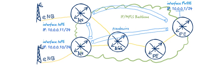
Another widely deployed case is mobile backhaul network in the service providers, where low-end routers, which doesn’t have BGP functionality, establish pseudowires using targeted LDP sessions to PE routers, what terminate these pseudowires into corresponding VRFs/VPRNs.
The following image shows basic idea of the routed VPLS:
What are we going to test?
I’ll configure routed VPLS for the second case (mobile backhaul). So we’ll have two PE routers, what terminates VPLS connectivity in Active/Standby fashion.
The image of the service will be provided later in the configuration section
Topology
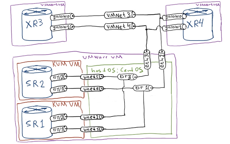
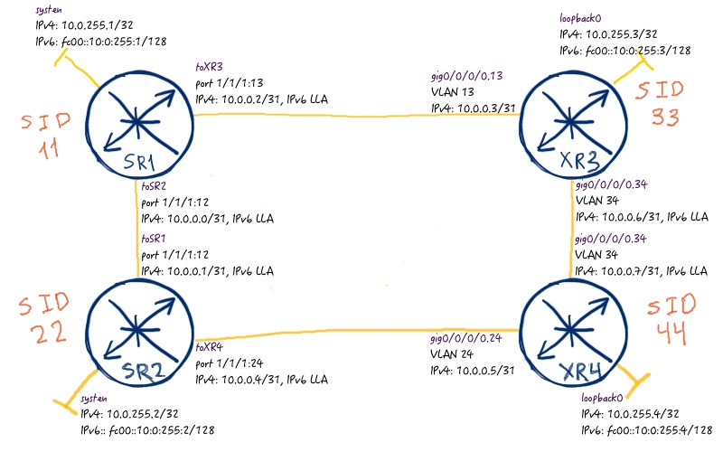
I use the classical physical topology with two Nokia (Alcatel-Lucent) VSRs and Cisco IOS XRv 9000:
Single area OSPF with process-id 1 is used as IGP, and this protocol is used as well to build IP/MPLS transport using Segment Routing (SPRING) extension. There is no BGP configured or used in this topology.
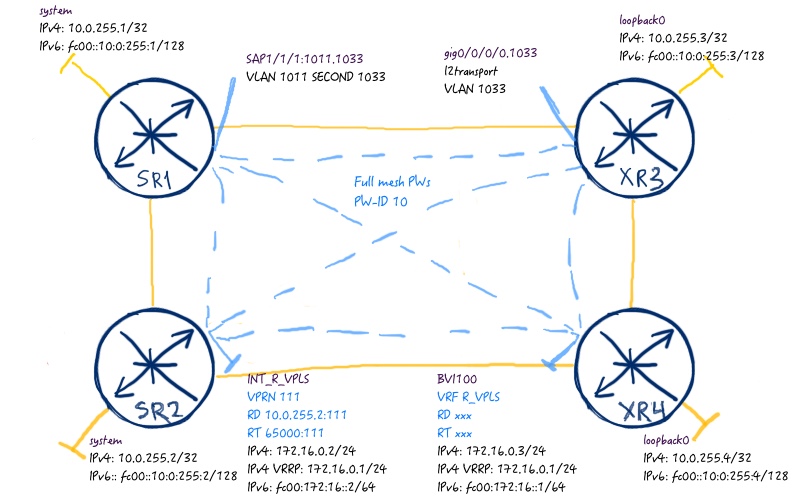
What we do here is we configure full mesh of pseudowires between all devices and terminate this pseudowires into VRF/VPRN at PE routers.It’s worth to make some comments about the configured service.
In order to provide resiliency for connection of base stations of mobile network (BTS for 2G, NB for 3G and eNB for 4G) we configure VRRP for this L3 service in VPRN/VRF over VPLS. So if one of the PE routers goes down, another one can take over its function, as VRRP IPv4/IPv6 address is used as default gateway for base stations.
Another key point is the pseudowire between SR1 and XR3. It’s not needed for 2G/3G networks as the connectivity between BTS/NB is necessary only to controller BSC/RNC that usually resides behind PE routers. In case of 4G this link in general is necessary to provide direct eNB to eNB connectivity (X2 interface). I say ”in general”, because there are some caveats caused by encryption stated by LTE standard, but it’s not the focus for the current article. So we say we just need this connectivity. There is no problem if you don’t fully understand described above, as you can understand it truly only if you works with them. There is useful picture (link), what helps to understand interfaces in mobile network.
Cisco IOS XRv 9000 doesn’t support dataplane for L2 MPLS services currently, so not all the outputs will be correct now, as there is no traffic sent/received over VPLS.
Now let’s see some outputs. The first point is to see if VPLS is established correctly at Nokia (Alcatel-Lucent) SR OS side:
A:SR2# show service id 10 base
===============================================================================
Service Basic Information
===============================================================================
Service Id : 10 Vpn Id : 0
Service Type : VPLS
Name : R_VPLS
Description : (Not Specified)
Customer Id : 2 Creation Origin : manual
Last Status Change: 04/28/2017 06:46:05
Last Mgmt Change : 04/28/2017 06:53:40
Etree Mode : Disabled
Admin State : Up Oper State : Up
MTU : 1492 Def. Mesh VC Id : 10
SAP Count : 1 SDP Bind Count : 3
Snd Flush on Fail : Disabled Host Conn Verify : Disabled
SHCV pol IPv4 : None
Propagate MacFlush: Disabled Per Svc Hashing : Disabled
Allow IP Intf Bind: Enabled
Fwd-IPv4-Mcast-To*: Disabled Fwd-IPv6-Mcast-To*: Disabled
Def. Gateway IP : None
Def. Gateway MAC : None
Temp Flood Time : Disabled Temp Flood : Inactive
Temp Flood Chg Cnt: 0
SPI load-balance : Disabled
SEID load-balance : Disabled
Src Tep IP : N/A
VSD Domain : <none>
——————————————————————————-
Service Access & Destination Points
——————————————————————————-
Identifier Type AdmMTU OprMTU Adm Opr
——————————————————————————-
sap:1/1/2:1022.1033 qinq 1522 1522 Up Up
sdp:11:10 M(10.0.255.1) Mesh 0 1492 Up Up
sdp:33:10 M(10.0.255.3) Mesh 0 1492 Up Up
sdp:44:10 M(10.0.255.4) Mesh 0 1492 Up Up
===============================================================================
And at Cisco IOS XR side:
RP/0/0/CPU0:XR4#show l2vpn bridge-domain bd-name R_VPLS
Legend: pp = Partially Programmed.
Bridge group: VPLS, bridge-domain: R_VPLS, id: 0, state: up, ShgId: 0, MSTi: 0
Aging: 300 s, MAC limit: 4000, Action: none, Notification: syslog
Filter MAC addresses: 0
ACs: 1 (1 up), VFIs: 1, PWs: 3 (3 up), PBBs: 0 (0 up), VNIs: 0 (0 up)
List of ACs:
BV100, state: up, BVI MAC addresses: 3
List of Access PWs:
List of VFIs:
VFI CORE (up)
Neighbor 10.0.255.1 pw-id 10, state: up, Static MAC addresses: 0
Neighbor 10.0.255.2 pw-id 10, state: up, Static MAC addresses: 0
Neighbor 10.0.255.3 pw-id 10, state: up, Static MAC addresses: 0
We see that pseudowires are established and works well. From VPLS side it is more or less enough.
What we else need to do is to check the routing table at our routers and the status of VRRP. As usually we start with Nokia (Alcatel-Lucent) VSR:
A:SR2# show router 111 route-table ipv4
===============================================================================
Route Table (Service: 111)
===============================================================================
Dest Prefix[Flags] Type Proto Age Pref
Next Hop[Interface Name] Metric
——————————————————————————-
172.16.0.0/24 Local Local 01h11m09s 0
INT_R_VPLS 0
——————————————————————————-
No. of Routes: 1
Flags: n = Number of times nexthop is repeated
B = BGP backup route available
L = LFA nexthop available
S = Sticky ECMP requested
===============================================================================
!
!
A:SR2# show router 111 route-table ipv6
==============================================================================
IPv6 Route Table (Service: 111)
===============================================================================
Dest Prefix[Flags] Type Proto Age Pref
Next Hop[Interface Name] Metric
——————————————————————————-
fc00:172:16::/64 Local Local 01h12m00s 0
INT_R_VPLS 0
——————————————————————————-
No. of Routes: 1
Flags: n = Number of times nexthop is repeated
B = BGP backup route available
L = LFA nexthop available
S = Sticky ECMP requested
===============================================================================
!
!
A:SR2# show router 111 vrrp instance
===============================================================================
VRRP Instances
===============================================================================
Interface Name VR Id Own Adm State Base Pri Msg Int
IP Opr Pol Id InUse Pri Inh Int
——————————————————————————-
INT_R_VPLS 1 No Up Master 110 1
IPv4 Up n/a 110 No
Backup Addr: 172.16.0.1
INT_R_VPLS 2 No Up Init 110 1
IPv6 Dn n/a 110 Yes
Backup Addr: fe80::a1:111:1
——————————————————————————-
Instances : 2
===============================================================================
As I’ve already said Cisco XRv 9000 doesn’t have currently data plane for L2 MPLS data plane, so the output of VRRP will be not correct at XR4, but I will provide it in any case:
RP/0/0/CPU0:XR4#show route vrf R_VPLS ipv4
Codes: C – connected, S – static, R – RIP, B – BGP, (>) – Diversion path
D – EIGRP, EX – EIGRP external, O – OSPF, IA – OSPF inter area
N1 – OSPF NSSA external type 1, N2 – OSPF NSSA external type 2
E1 – OSPF external type 1, E2 – OSPF external type 2, E – EGP
i – ISIS, L1 – IS-IS level-1, L2 – IS-IS level-2
ia – IS-IS inter area, su – IS-IS summary null, * – candidate default
U – per-user static route, o – ODR, L – local, G – DAGR, l – LISP
A – access/subscriber, a – Application route
M – mobile route, r – RPL, (!) – FRR Backup path
Gateway of last resort is not set
C 172.16.0.0/24 is directly connected, 00:16:43, BVI100
L 172.16.0.1/32 [0/0] via 172.16.0.1, 00:16:35, BVI100
L 172.16.0.3/32 is directly connected, 00:16:43, BVI100
!
!
RP/0/0/CPU0:XR4#show route vrf R_VPLS ipv6
C fc00:172:16::/64 is directly connected,
00:17:07, BVI100
L fc00:172:16::3/128 is directly connected,
00:17:07, BVI100!
!
RP/0/0/CPU0:XR4#show vrrp
IPv4 Virtual Routers:
A indicates IP address owner
| P indicates configured to preempt
| |
Interface vrID Prio A P State Master addr VRouter addr
BV100 1 100 P Master local 172.16.0.1
IPv6 Virtual Routers:
A indicates IP address owner
| P indicates configured to preempt
| |
Interface vrID Prio A P State Master addr VRouter addr
BV100 2 100 P Master local fe80::a1:111:1
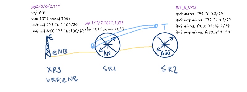
As Nokia (Alcatel-Lucent) VSR (SR 7750) supports data plane for MPLS L2 VPN services, we can test it’s part. So I create a VRF eNB at XR3 and connect it as client on SAP at SR1 so that it terminates then in corresponding VPRN in SR2. Here is the test topology:
Here is the test ping for IPv4 address from XR3 to SR2:
RP/0/0/CPU0:XR3# ping vrf eNB 172.16.0.1
Wed Mar 29 23:11:02.814 UTC
Type escape sequence to abort.
Sending 5, 100-byte ICMP Echos to 172.16.0.1, timeout is 2 seconds:
!!!!!
Success rate is 100 percent (5/5), round-trip min/avg/max = 1/5/9 ms
!
!
RP/0/0/CPU0:XR3#show arp vrf eNB
——————————————————————————-
0/0/CPU0
——————————————————————————-
Address Age Hardware Addr State Type Interface
172.16.0.1 00:02:43 0000.5e00.0101 Dynamic ARPA GigabitEthernet0/0/0/0.111
172.16.0.100 – 0050.5631.b773 Interface ARPA GigabitEthernet0/0/0/0.111
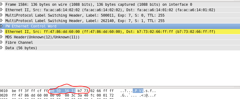
Wireshark helps us to see what is going on the wire:
Now we can check als FDB (mac address table for VPLS):
A:SR1# show service fdb-mac
===============================================================================
Service Forwarding Database
===============================================================================
ServId MAC Source-Identifier Type Last Change
Age
——————————————————————————-
10 00:00:5e:00:01:01 sdp:22:10 L/0 04/28/17 06:53:42
10 00:50:56:31:b7:73 sap:1/1/2:1011.1033 L/0 04/28/17 08:11:24
10 02:66:ff:ff:ff:47 sdp:22:10 L/59 04/28/17 08:14:54
——————————————————————————-
No. of Entries: 3
——————————————————————————-
Legend: L=Learned O=Oam P=Protected-MAC C=Conditional S=Static
===============================================================================
!
!
A:SR2# show service fdb-mac
===============================================================================
Service Forwarding Database
===============================================================================
ServId MAC Source-Identifier Type Last Change
Age
——————————————————————————-
10 00:00:5e:00:01:01 cpm Intf 04/28/17 06:53:44
10 00:50:56:31:b7:73 sdp:11:10 L/30 04/28/17 08:11:30
10 02:66:ff:ff:ff:47 cpm Intf 04/28/17 06:38:33
——————————————————————————-
No. of Entries: 3
——————————————————————————-
Legend: L=Learned O=Oam P=Protected-MAC C=Conditional S=Static
===============================================================================
The same exercise for IPv6 just to show that it works as well:
ping vrf eNB fc00:172:16::1
And Wireshark output:
Seems strange? We have dicussed once that Wireshark doesn’t always understand MPLS L2 VPN packets correctly. Look, it says that we have control word field, though we don’t have it:
If we take a look on control-world bits and also on the next couple, we see that it’s just MAC address of eNB:
A:SR2# show router 111 neighbor
===============================================================================
Neighbor Table (Service: 111)
===============================================================================
IPv6 Address Interface
MAC Address State Expiry Type RTR
——————————————————————————-
fc00:172:16::100 INT_R_VPLS
00:50:56:31:b7:73 STALE 03h59m52s Dynamic No
fe80::250:56ff:fe31:b773 INT_R_VPLS
00:50:56:31:b7:73 STALE 03h43m36s Dynamic No
——————————————————————————-
No. of Neighbor Entries: 2
===============================================================================
There is one more possibility, how you can build VPLS in Nokia (Alcatel-Lucent) SR OS and in Cisco IOS XR. In Nokia you can used spoke-sdp instead as well as in Cisco your put neighbours outside of VFI context. By default, such configuration will bring down your network, because in both cases traffic coming from pseudowire will be replicated to other, meaning that single packet will cause broadcast storm and continuous loop. Such problem doesn’t exist in VFI/mesh-sdp configuration, because you have split-horizon activated by default activated there and VFI or all mesh-sdps are treated as single interface. If you implement (what is highly not recommended from me) or operate the network with such installation, you need to take care of manual split-horizon-groups (SHG) configuration across spoke-sdps/neighbours so that no loops occur.
Conclusion
Routed VPLS is quite useful and widely used technology in service provider networks as well as in data centre. Though EVPN tends to overtake leadership here due to better design and functionality, VPLS will still be in place for a long time. And it’s OK, because with the proper planning and implementation it makes good job. Take care and good bye!