Multicast for IPv4/IPv6 in Nokia SR OS and Cisco IOS XR
Anton Karneliuk
Hello my friend,
A couple of last articles were dedicated to the SDN topic, and though there are still a lot of things to clear, I’ll right about something different now. In this and a couple of next articles we’ll talk about multicast.
1 2 3 4 5
No part of this blogpost could be reproduced, stored in a
retrieval system, or transmitted in any form or by any
means, electronic, mechanical or photocopying, recording,
or otherwise, for commercial purposes without the
prior permission of the author.
Disclaimer
The reason why I step away from SDN now is that further deep dive requires the controller. I’ve started some tests already but it takes much more time to familiarize myself to the controller than I’ve planned.
Brief overview
In modern network it’s difficult to overestimate the use of multicast traffic. Video streaming (including IP TV) and multipoint video-conferences are just two the easiest examples.
Nowadays there are different flavors of multicast. The first one is called ASM (Any Source Multicast) and means that any host in the network can send multicast traffic and corresponding distribution tree will be build. Though it was developed historically earlier than other multicast flavors, it’s quite complex from signaling prospective. The next one is SSM (Source Specific Multicast), where the client (receiver) itself defines from which source it wants to receive the traffic. From the signaling it’s quite straightforward as multicast distribution tree is built from the client directly to the source. These two types for IPv4/IPv6 traffic are subject for this article.
Other types as MVPN (multicast VPN) and LSM (label switched multicast) will be covered in separate article later.
What are we going to test?
We’ll configure and test the following scenarios for multicast data plane:
ASM for IPv4
SSM for IPv4
ASM for IPv6
SSM for IPv6
In ASM case we’ll use BSR for distribution information about RP (rendezvous point).
Software version
For tests in this lab I use the following versions of software for routers:
Nokia (Alcatel-Lucent) SR OS 14.0.R4
Cisco IOS XRv 6.1.2
I had to switch Nokia (Alcatel-Lucent) SR OS version from 15.0.R4 back to 14.0.R4, due to some problems with multicast configuration there. As soon as I clear them I’ll update you
Topology
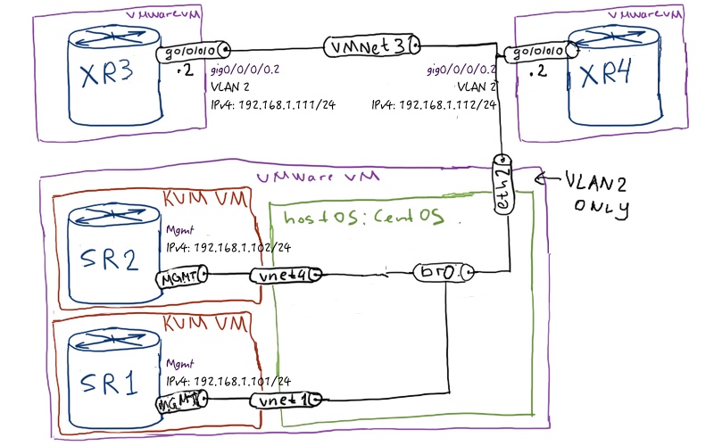
Physical topology is rather small for such lab, but is maximal for my laptop:
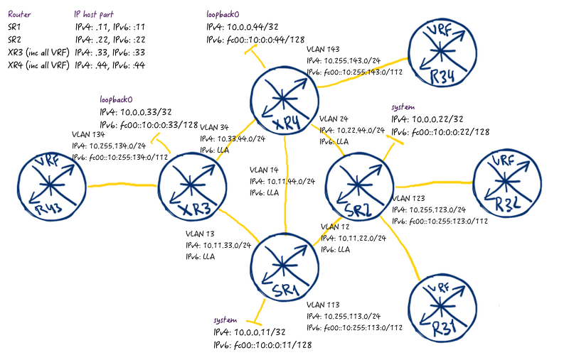
So I need to invent way to extend the number of routers in order to be able to test multicasting properly. Here we go:
As you see, all the hosts are VRFs configured in Cisco IOS XR (R31, R32, R34 at XR3 and R43 at XR4) routers. You might remember, I have used this approach during configuration of BGP (link). These hosts have only default static route both for IPv4 and IPv6 pointing to the core router. As core routers we have 2 Nokia (Alcatel-Lucent) VSR (SR7750) and 2 Cisco IOS XRv (ASR 9000) routers. They use ISIS in multi-topology fashion both for IPv4/IPv6 and announce only passive interfaces, which are loopbacks 0 /system interfaces and interfaces towards multicast clients.
Some default values for Nokia (Alcatel-Lucent) SR OS and Cisco IOS XR
There are different versions of PIM, MLD and IGMP. Luckily in Cisco IOS XR and Nokia (Alcatel-Lucent) SR OS they are the same:
Protocol
Nokia (Alcatel-Lucent) SR OS
Cisco IOS XR
PIM
version 2
version 2
IGMP
version 3
version 3
MLD
version 2
version 2
What does it mean for us? It means that we don’t need to change protocol version somewhere and therefore it’s easier to configure interoperable solution.
Configuration of ASM (Any Source Multicast) for IPv4
In nutshell configuration of ASM flavor of multicast is quite easy. You just need to enable PIM and IGMP on appropriate interfaces and configure information about RP somehow. In this lab we’ll use BSR mechanism to distribute this information. To make things more interesting, we’ll do the following configuration:
Nokia (Alcatel-Lucent) SR OS router SR1 will be RP for group 238.0.0.0/8
Cisco IOS XR router XR4 will be RP for group 239.0.0.0/8
Both these routers also act as BSR having SR1 as active and XR4 as backup BSR
All routers are using PIM/IGMP
Multicast clients R31, R32, R34 join groups 238.0.0.124 and 239.0.0.124
And here how we translate these requirements in actual code lines:
Nokia (Alcatel-Lucent) SR OS
Cisco IOS XR
SR1
XR3
A:SR1>edit-cfg# candidate view
=========================
configure
router
igmp
interface “toCLIENT”
no shutdown
exit
interface “toSR2”
no shutdown
exit
interface “toXR3”
no shutdown
exit
interface “toXR4”
no shutdown
exit
no shutdown
exit
pim
interface “toCLIENT”
exit
interface “toSR2”
exit
interface “toXR3”
exit
interface “toXR4”
exit
apply-to all
rp
static
exit
bsr-candidate
priority 50
address 10.0.0.11
no shutdown
exit
rp-candidate
address 10.0.0.11
group-range 224.0.0.0/4
group-range 238.0.0.0/8
no shutdown
exit
exit
no shutdown
exit
exit
exit
=========================
You see, we just enable PIM and IGMP and mainly that’s it. For RP and BSR we do corresponding configuration at SR1 and XR3. I configured on the customer-facing interfaces at core routers dr-priority so that clients can’t take this role.
At emulation of multicast clients, we have to configure both PIM/IGMP as well
Let’s check if routers in the network already learned information about RP:
A:SR2# show router pim rp ipv4
===============================================================================
PIM RP Set ipv4
===============================================================================
Group Address Hold Expiry
RP Address Type Prio Time Time
——————————————————————————-
224.0.0.0/4
10.0.0.11 Dynamic 192 150 0d 00:02:02
10.0.0.44 Dynamic 192 75 0d 00:02:02
238.0.0.0/8
10.0.0.11 Dynamic 192 150 0d 00:02:02
239.0.0.0/8
10.0.0.44 Dynamic 192 75 0d 00:02:02
——————————————————————————-
Group Prefixes : 3
===============================================================================
!
!
RP/0/0/CPU0:XR3#show pim ipv4 rp mapping
PIM Group-to-RP Mappings
Group(s) 238.0.0.0/8
RP 10.0.0.11 (?), v2
Info source: 10.33.44.44 (?), elected via bsr, priority 192, holdtime 150
Uptime: 00:11:45, expires: 00:02:12
Group(s) 239.0.0.0/8
RP 10.0.0.44 (?), v2
Info source: 10.33.44.44 (?), elected via bsr, priority 192, holdtime 75
Uptime: 00:20:02, expires: 00:00:57
Group(s) 224.0.0.0/4
RP 10.0.0.44 (?), v2
Info source: 10.33.44.44 (?), elected via bsr, priority 192, holdtime 75
Uptime: 00:20:02, expires: 00:00:57
Group(s) 224.0.0.0/4
RP 10.0.0.11 (?), v2
Info source: 10.33.44.44 (?), elected via bsr, priority 192, holdtime 150
Uptime: 00:11:45, expires: 00:02:12
You have seen, we have configured a 3 multicast clients (R31, R32 and R34) to join groups 238.0.0.124 and 239.0.0.124
Probably it’s not the best group choice due to the fact that both of these IPv4 addresses will be mapped to the same Ethernet multicast address 01:00:5E:10:00:7C. If you have questions to translations, read my big multicast article
Now we check PIM tables both at Nokia (Alcatel-Lucent) SR OS router SR1 and Cisco IOS XR router XR3 to see how the (*, G) groups looks like:
A:SR1# show router pim group ipv4
===============================================================================
Legend: A = Active S = Standby
===============================================================================
PIM Groups ipv4
===============================================================================
Group Address Type Spt Bit Inc Intf No.Oifs
Source Address RP State Inc Intf(S)
——————————————————————————-
224.0.1.40 (*,G) toXR4 0
* 10.0.0.44
238.0.0.124 (*,G) 3
* 10.0.0.11
239.0.0.124 (*,G) toXR4 1
* 10.0.0.44
——————————————————————————-
Groups : 3
===============================================================================
!
!
RP/0/0/CPU0:XR4#show pim ipv4 topology
IP PIM Multicast Topology Table
Entry state: (*/S,G)[RPT/SPT] Protocol Uptime Info
Entry flags: KAT – Keep Alive Timer, AA – Assume Alive, PA – Probe Alive
RA – Really Alive, IA – Inherit Alive, LH – Last Hop
DSS – Don’t Signal Sources, RR – Register Received
SR – Sending Registers, SNR – Sending Null Registers
E – MSDP External, EX – Extranet
MFA – Mofrr Active, MFP – Mofrr Primary, MFB – Mofrr Backup
DCC – Don’t Check Connected, ME – MDT Encap, MD – MDT Decap
MT – Crossed Data MDT threshold, MA – Data MDT Assigned
SAJ – BGP Source Active Joined, SAR – BGP Source Active Received,
SAS – BGP Source Active Sent, IM – Inband mLDP, X – VxLAN
Interface state: Name, Uptime, Fwd, Info
Interface flags: LI – Local Interest, LD – Local Dissinterest,
II – Internal Interest, ID – Internal Dissinterest,
LH – Last Hop, AS – Assert, AB – Admin Boundary, EX – Extranet,
BGP – BGP C-Multicast Join, BP – BGP Source Active Prune,
MVS – MVPN Safi Learned, MV6S – MVPN IPv6 Safi Learned
.
(*,224.0.1.40) DM Up: 00:18:03 RP: 0.0.0.0
JP: Null(never) RPF: Null,0.0.0.0 Flags: LH DSS
Loopback0 00:18:03 off LI II LH
GigabitEthernet0/0/0/0.143 00:18:02 off LI LH
.
(*,238.0.0.124) SM Up: 00:18:02 RP: 10.0.0.11
JP: Join(00:00:06) RPF: GigabitEthernet0/0/0/0.14,10.11.44.11 Flags: LH
GigabitEthernet0/0/0/0.143 00:18:02 fwd LI LH
.
(*,239.0.0.124) SM Up: 00:18:02 RP: 10.0.0.44*
JP: Join(never) RPF: Decapstunnel1,10.0.0.44 Flags: LH
GigabitEthernet0/0/0/0.14 00:09:17 fwd Join(00:03:12)
GigabitEthernet0/0/0/0.24 00:11:55 fwd Join(00:02:34)
GigabitEthernet0/0/0/0.143 00:18:02 fwd LI LH
This topology command in Cisco IOS XR is something new, what was not available in the ordinary Cisco IOS / IOS XE.
There are 2 more useful commands in Cisco IOS XR: “show mrib ipv4 route” and “show mfib ipv4 route”. I don’t know analogues in Nokia (Alcatel-Lucent) SR OS for them.
We don’t make extensive checks to see PIM groups’ states at each router, but so far everything looks nice. There is only one opportunity to verify whether our multicast transmission works, that is to ping multicast address. Client VRF R43 will be multicast sender:
RP/0/0/CPU0:XR4#ping vrf R43 238.0.0.124 count 5
Sending 5, 100-byte ICMP Echos to 238.0.0.124, timeout is 2 seconds:
Reply to request 0 from 10.255.113.33, 9 ms
Reply to request 1 from 10.255.113.33, 9 ms
Reply to request 2 from 10.255.113.33, 1 ms
Reply to request 3 from 10.255.113.33, 9 ms
Reply to request 4 from 10.255.113.33, 1 ms
!
!
RP/0/0/CPU0:XR4#ping vrf R43 239.0.0.124 count 5
Sending 5, 100-byte ICMP Echos to 239.0.0.124, timeout is 2 seconds:
.
Reply to request 1 from 10.255.143.33, 1 ms
Reply to request 1 from 10.255.113.33, 19 ms
Reply to request 1 from 10.255.123.33, 49 ms
Reply to request 2 from 10.255.143.33, 1 ms
Reply to request 2 from 10.255.113.33, 19 ms
Reply to request 2 from 10.255.113.33, 19 ms
Reply to request 2 from 10.255.123.33, 29 ms
Reply to request 3 from 10.255.143.33, 1 ms
Reply to request 3 from 10.255.113.33, 19 ms
Reply to request 3 from 10.255.123.33, 49 ms
Reply to request 4 from 10.255.143.33, 1 ms
Reply to request 4 from 10.255.113.33, 9 ms
Reply to request 4 from 10.255.123.33, 19 ms
Oops, something is going wrong. We have just figure out that for the group 239.0.0.124, where Cisco XR4 is RP, everything is working fine. But for another group 238.0.0.134, where SR1 is RP, only one client responds, which is directly connected to SR1. Let’s make some troubleshooting.
RP/0/0/CPU0:XR3#show mrib ipv4 route 238.0.0.124
IP Multicast Routing Information Base
Entry flags: L – Domain-Local Source, E – External Source to the Domain,
C – Directly-Connected Check, S – Signal, IA – Inherit Accept,
IF – Inherit From, D – Drop, ME – MDT Encap, EID – Encap ID,
MD – MDT Decap, MT – MDT Threshold Crossed, MH – MDT interface handle
CD – Conditional Decap, MPLS – MPLS Decap, EX – Extranet
MoFE – MoFRR Enabled, MoFS – MoFRR State, MoFP – MoFRR Primary
MoFB – MoFRR Backup, RPFID – RPF ID Set, X – VXLAN
Interface flags: F – Forward, A – Accept, IC – Internal Copy,
NS – Negate Signal, DP – Don’t Preserve, SP – Signal Present,
II – Internal Interest, ID – Internal Disinterest, LI – Local Interest,
LD – Local Disinterest, DI – Decapsulation Interface
EI – Encapsulation Interface, MI – MDT Interface, LVIF – MPLS Encap,
EX – Extranet, A2 – Secondary Accept, MT – MDT Threshold Crossed,
MA – Data MDT Assigned, LMI – mLDP MDT Interface, TMI – P2MP-TE MDT Interface
IRMI – IR MDT Interface
.
(10.255.134.44,238.0.0.124) RPF nbr: 10.255.134.44 Flags: RPF
Up: 00:01:26
Incoming Interface List
GigabitEthernet0/0/0/0.134 Flags: A, Up: 00:01:24
Outgoing Interface List
GigabitEthernet0/0/0/0.13 Flags: F NS, Up: 00:01:26
When we check XR3, we see that only link to SR is added to OIL (output interface list). If we compare it to group 239.0.0.124, we see two interfaces in OIL:
RP/0/0/CPU0:XR3#show mrib ipv4 route 239.0.0.124
.
(10.255.134.44,239.0.0.124) RPF nbr: 10.255.134.44 Flags: RPF
Up: 00:00:06
Incoming Interface List
GigabitEthernet0/0/0/0.134 Flags: A, Up: 00:00:06
Outgoing Interface List
GigabitEthernet0/0/0/0.13 Flags: F NS, Up: 00:00:04
GigabitEthernet0/0/0/0.34 Flags: F NS, Up: 00:00:06
So somehow XR4 doesn’t join SPT to XR3. Let’s check XR4 multicast topology:
RP/0/0/CPU0:XR4#show mrib ipv4 route 239.0.0.124
(*,239.0.0.124) RPF nbr: 10.0.0.44 Flags: C RPF
Up: 00:42:50
Incoming Interface List
Decapstunnel0 Flags: A NS, Up: 00:42:08
Outgoing Interface List
GigabitEthernet0/0/0/0.14 Flags: F NS, Up: 00:42:08
GigabitEthernet0/0/0/0.24 Flags: F NS, Up: 00:42:08
GigabitEthernet0/0/0/0.143 Flags: F NS LI, Up: 00:42:50
.
(10.255.134.44,239.0.0.124) RPF nbr: 10.33.44.33 Flags: L RPF
Up: 00:01:59
Incoming Interface List
GigabitEthernet0/0/0/0.34 Flags: A, Up: 00:01:59
Outgoing Interface List
GigabitEthernet0/0/0/0.24 Flags: F NS, Up: 00:01:59
GigabitEthernet0/0/0/0.143 Flags: F NS, Up: 00:01:59
!
!
RP/0/0/CPU0:XR4#show mrib ipv4 route 238.0.0.124
(*,238.0.0.124) RPF nbr: 10.11.44.11 Flags: C RPF
Up: 00:42:56
Incoming Interface List
GigabitEthernet0/0/0/0.14 Flags: A NS, Up: 00:42:42
Outgoing Interface List
GigabitEthernet0/0/0/0.143 Flags: F NS LI, Up: 00:42:56
What is clear that XR4 even doesn’t know about multicast stream from R43. It means that SR1 doesn’t send the appropriate multicast traffic alongside RPT. Or it might send this traffic, but XR4 doesn’t receive it…
After some experiments (actually packet capture on different interfaces) I came to conclusion, that the second was correct. We must understand that out virtual routers aren’t connected directly to each other, but rather through bridges. And these bridges by default perform IGMP snooping function. Here we come to the point that Cisco IOS XR and Nokia (Alcatel-Lucent) SR OS behave differently regarding multicast. Cisco seems to see IGMP reports or PIM join/prune messages so that IGMP snooping functionality on underlying bridges understands how to send multicast traffic and Nokia (Alcatel-Lucent) SR OS doesn’t do it or does in another way.
Long story short, this article explains the details about IGMP/MLD snooping in Linux bridges and how to disable it. For our lab setup we need to update bridges with the following configuration:
Let’s perform the similar multicast test to check if everything works proper now:
RP/0/0/CPU0:XR4#ping vrf R43 238.0.0.124 count 5
Sending 5, 100-byte ICMP Echos to 238.0.0.124, timeout is 2 seconds:
.
Reply to request 1 from 10.255.143.33, 9 ms
Reply to request 1 from 10.255.113.33, 29 ms
Reply to request 1 from 10.255.123.33, 29 ms
Reply to request 2 from 10.255.113.33, 9 ms
Reply to request 2 from 10.255.113.33, 9 ms
Reply to request 2 from 10.255.143.33, 9 ms
Reply to request 2 from 10.255.143.33, 9 ms
Reply to request 2 from 10.255.143.33, 9 ms
Reply to request 2 from 10.255.123.33, 29 ms
Reply to request 2 from 10.255.123.33, 29 ms
Reply to request 3 from 10.255.143.33, 1 ms
Reply to request 3 from 10.255.113.33, 9 ms
Reply to request 3 from 10.255.123.33, 9 ms
Reply to request 4 from 10.255.143.33, 9 ms
Reply to request 4 from 10.255.113.33, 19 ms
Reply to request 4 from 10.255.123.33, 19 ms
!
!
RP/0/0/CPU0:XR4#ping vrf R43 239.0.0.124 count 5
Sending 5, 100-byte ICMP Echos to 239.0.0.124, timeout is 2 seconds:
.
Reply to request 1 from 10.255.143.33, 1 ms
Reply to request 1 from 10.255.113.33, 49 ms
Reply to request 1 from 10.255.123.33, 49 ms
Reply to request 2 from 10.255.143.33, 1 ms
Reply to request 2 from 10.255.123.33, 19 ms
Reply to request 2 from 10.255.113.33, 29 ms
Reply to request 2 from 10.255.113.33, 29 ms
Reply to request 2 from 10.255.123.33, 39 ms
Reply to request 2 from 10.255.123.33, 39 ms
Reply to request 3 from 10.255.143.33, 9 ms
Reply to request 3 from 10.255.113.33, 29 ms
Reply to request 3 from 10.255.123.33, 29 ms
Reply to request 4 from 10.255.143.33, 1 ms
Reply to request 4 from 10.255.113.33, 1 ms
Reply to request 4 from 10.255.123.33, 1 ms
Looks good. Let’s go further to SSM IPv4.
Configuration of SSM (Source Specific Multicast) for IPv4
For this technology we’ll configure the following scenario:
IPv4 range 232.0.0.0/8 is used for multicasting
Client R32 joins group 232.2.2.2 with the source 10.255.134.44
Client R43 joins group 232.4.4.4 with the source 10.255.123.33
And here how we translate these requirements in actual code lines:
RP/0/0/CPU0:XR4(config)#show conf
!
router igmp
vrf R43
interface GigabitEthernet0/0/0/0.134
join-group 232.4.4.4 include 10.255.123.33
!
!
!
end
You see that we configure only multicast clients without configuring the range. If we check the status into details, we see that SSM range is already predefined both in Nokia (Alcatel-Lucent) SR OS and Cisco IOS XR:
A:SR1# show router pim status | match Def
SSM-Default-Range : Enabled
!
!
RP/0/0/CPU0:XR4#show pim ipv4 group-map | inc “^Group|SSM”
Group Range Proto Client Groups RP address Info
232.0.0.0/8* SSM config 1 0.0.0.0
IPv4 address range “232.0.0.0/8” is defined in RFC4607 as SSM range, that’s why we don’t need to configure it explicitly. Let’s briefly check PIM topology at SR2 and XR3:
:SR2# show router pim group
===============================================================================
Legend: A = Active S = Standby
===============================================================================
PIM Groups ipv4
===============================================================================
Group Address Type Spt Bit Inc Intf No.Oifs
Source Address RP State Inc Intf(S)
——————————————————————————-
224.0.1.40 (*,G) toXR4 1
* 10.0.0.44 232.2.2.2 (S,G) spt toSR1 1 10.255.134.44 10.0.0.44 232.4.4.4 (S,G) spt toCLIENT 1 10.255.123.33 10.0.0.11
238.0.0.124 (*,G) toSR1 1
* 10.0.0.11
239.0.0.124 (*,G) toXR4 1
* 10.0.0.44
——————————————————————————-
Groups : 5
===============================================================================
!
!
RP/0/0/CPU0:XR3#show pim ipv4 topology
(*,224.0.1.40) DM Up: 03:02:25 RP: 0.0.0.0
JP: Null(never) RPF: Null,0.0.0.0 Flags: LH DSS
Loopback0 03:02:25 off LI II LH
GigabitEthernet0/0/0/0.134 03:01:43 off LI
. (10.255.134.44,232.2.2.2)SPT SSM Up: 00:25:02 JP: Join(00:01:06) RPF: GigabitEthernet0/0/0/0.134,10.255.134.44* Flags: GigabitEthernet0/0/0/0.13 00:25:02 fwd Join(00:03:24) . (10.255.123.33,232.4.4.4)SPT SSM Up: 00:24:20 JP: Join(00:00:31) RPF: GigabitEthernet0/0/0/0.34,10.33.44.44 Flags: GigabitEthernet0/0/0/0.134 00:24:20 fwd Join(00:03:10) LI
You see that the groups are already has form (S,G) and therefore no groups are signalled to RP. Let’s perform a brief ping test:
RP/0/0/CPU0:XR3#ping vrf R32 232.4.4.4 count 5
Sending 5, 100-byte ICMP Echos to 232.4.4.4, timeout is 2 seconds:
Reply to request 0 from 10.255.134.44, 1 ms
Reply to request 1 from 10.255.134.44, 9 ms
Reply to request 2 from 10.255.134.44, 19 ms
Reply to request 3 from 10.255.134.44, 19 ms
Reply to request 4 from 10.255.134.44, 1 ms
!
!
RP/0/0/CPU0:XR4#ping vrf R43 232.2.2.2 rep 5
Sending 5, 100-byte ICMP Echos to 232.2.2.2, timeout is 2 seconds:
Reply to request 0 from 10.255.123.33, 19 ms
Reply to request 1 from 10.255.123.33, 9 ms
Reply to request 2 from 10.255.123.33, 1 ms
Reply to request 3 from 10.255.123.33, 9 ms
Reply to request 4 from 10.255.123.33, 19 ms
After we have solved the problem with IGMP snooping in underlying Linux bridges, multicast configuration is quite easy and its operation is straightforward. Now we can move further to IPv6 multicasting.
Configuration of ASM (Any Source Multicast) for IPv6
We have gathered some experience regarding multicast in Nokia (Alcatel-Lucent) SR OS and Cisco IOS XR upon configuring IPv4. Now it’s time to reuse it for IPv6. We’ll configure the following scenario:
Nokia (Alcatel-Lucent) SR OS router SR1 will be RP for group ff05::238:0:0:124/80
Cisco IOS XR router XR4 will be RP for group ff05::239:0:0:124/80
Both these routers also act as BSR having SR1 as active and XR4 as backup BSR
All routers are using PIM/MLD
Multicast clients R31, R34, R43 join groups ff05::238:0:0:124 and ff05::239:0:0:124
To accomplish this scenario we do the following actions:
Nokia (Alcatel-Lucent) SR OS
Cisco IOS XR
SR1
XR3
A:SR1>edit-cfg# candidate view
=========================
configure
router
mld
interface “toCLIENT”
no shutdown
exit
interface “toSR2”
no shutdown
exit
interface “toXR3”
no shutdown
exit
interface “toXR4”
no shutdown
exit
no shutdown
exit
pim
no ipv6-multicast-disable
rp
ipv6
bsr-candidate
priority 50
address fc00::10:0:0:11
no shutdown
exit
rp-candidate
address fc00::10:0:0:11
group-range ff05::/16
group-range ff05::238:0:0:0/80
no shutdown
exit
exit
exit
exit
exit
exit
=========================
As you may see, the configuration at Cisco IOS XR for IPv6 multicasting is fully identical to IPv4 multicast besides keyword “ipv6” vs “ipv4”. In Nokia (Alcatel-Lucent) SR OS it’s even easier, because we just configure it to use PIM for ipv6 in addition to ipv4 and enable MLD on corresponding interfaces (you can just copy-paste configuration of igmp).
We start checks of IPv6 multicast infrastructure with RP information, just in the same way we did for IPv4 multicast:
A:SR2# show router pim rp ipv6
===============================================================================
PIM RP Set ipv6
===============================================================================
Group Address Hold Expiry
RP Address Type Prio Time Time
——————————————————————————-
ff05::/16
fc00::10:0:0:11 Dynamic 192 150 0d 00:02:06
fc00::10:0:0:44 Dynamic 192 75 0d 00:02:06
ff05::238:0:0:0/80
fc00::10:0:0:11 Dynamic 192 150 0d 00:02:06
ff05::239:0:0:0/80
fc00::10:0:0:44 Dynamic 192 75 0d 00:02:06
——————————————————————————-
Group Prefixes : 3
===============================================================================
!
!
RP/0/0/CPU0:XR3#show pim ipv6 group-map info-source
IP PIM Group Mapping Table
(* indicates group mappings being used)
(+ indicates BSR group mappings active in MRIB)
.
Group Range Proto Client Groups
.
ff05::238:0:0:0/80* SM bsr+ 1
RP: fc00::10:0:0:11
From: fe80::44(00:02:09)
.
ff05::239:0:0:0/80* SM bsr+ 1
RP: fc00::10:0:0:44
From: fe80::44(00:00:54)
.
ff05::/16* SM bsr 0
RP: fc00::10:0:0:44
From: fe80::44(00:00:54)
.
ff05::/16* SM bsr+ 0
RP: fc00::10:0:0:11
From: fe80::44(00:02:09)
I’ve significantly reduced output from Cisco IOS XR, because by default it includes all SSM groups for IPv6, which is quite long list. What is really important in this case, all information about configured RP and associated ranges are here. Now let’s check the PIM topology information in order to find evidence of IPv6 multicast clients’ registrations to multicast distribution tree:
A:SR1# show router pim group ipv6
===============================================================================
Legend: A = Active S = Standby
===============================================================================
PIM Groups ipv6
===============================================================================
Group Address Type Spt Bit Inc Intf No.Oifs
Source Address RP State Inc Intf(S)
——————————————————————————-
ff05::238:0:0:124 (*,G) 3
* fc00::10:0:0:11
ff05::239:0:0:124 (*,G) toXR4 1
* fc00::10:0:0:44
——————————————————————————-
Groups : 2
===============================================================================
!
!
RP/0/0/CPU0:XR4#show pim ipv6 topology
IP PIM Multicast Topology Table
Entry state: (*/S,G)[RPT/SPT] Protocol Uptime Info
Entry flags: KAT – Keep Alive Timer, AA – Assume Alive, PA – Probe Alive
RA – Really Alive, IA – Inherit Alive, LH – Last Hop
DSS – Don’t Signal Sources, RR – Register Received
SR – Sending Registers, SNR – Sending Null Registers
E – MSDP External, EX – Extranet
MFA – Mofrr Active, MFP – Mofrr Primary, MFB – Mofrr Backup
DCC – Don’t Check Connected, ME – MDT Encap, MD – MDT Decap
MT – Crossed Data MDT threshold, MA – Data MDT Assigned
SAJ – BGP Source Active Joined, SAR – BGP Source Active Received,
SAS – BGP Source Active Sent, IM – Inband mLDP, X – VxLAN
Interface state: Name, Uptime, Fwd, Info
Interface flags: LI – Local Interest, LD – Local Dissinterest,
II – Internal Interest, ID – Internal Dissinterest,
LH – Last Hop, AS – Assert, AB – Admin Boundary, EX – Extranet,
BGP – BGP C-Multicast Join, BP – BGP Source Active Prune,
MVS – MVPN Safi Learned, MV6S – MVPN IPv6 Safi Learned
.
(*,ff05::238:0:0:124)
SM Up: 00:32:44 JP: Join(00:01:05) Flags:
RP: fc00::10:0:0:11
RPF: GigabitEthernet0/0/0/0.14,fe80::11
GigabitEthernet0/0/0/0.143 00:32:44 fwd Join(00:03:07) LI
.
(*,ff05::239:0:0:124)
SM Up: 00:32:44 JP: Join(never) Flags:
RP: fc00::10:0:0:44*
RPF: Decaps6tunnel0,fc00::10:0:0:44
GigabitEthernet0/0/0/0.14 00:13:22 fwd Join(00:03:07)
GigabitEthernet0/0/0/0.34 00:16:45 fwd Join(00:03:15)
GigabitEthernet0/0/0/0.143 00:32:44 fwd Join(00:02:39) LI
So far PIM topology looks quite promising and we’ll make our verifications by issuing ipv6 ping from multicast client, which this time will be R32:
RP/0/0/CPU0:XR3#ping vrf R32 ff05::238:0:0:124 rep 5 source fc00::10:255:123:33
Sending 5, 100-byte ICMP Echos to ff05::238:0:0:124, timeout is 2 seconds:
.
Reply to request 1 from fc00::10:255:113:33, 49 ms
Reply to request 1 from fc00::10:255:143:33, 59 ms
Reply to request 1 from fc00::10:255:134:44, 59 ms
Reply to request 2 from fc00::10:255:143:33, 39 ms
Reply to request 2 from fc00::10:255:134:44, 49 ms
Reply to request 2 from fc00::10:255:113:33, 59 ms
Reply to request 3 from fc00::10:255:143:33, 19 ms
Reply to request 3 from fc00::10:255:113:33, 29 ms
Reply to request 3 from fc00::10:255:134:44, 29 ms
Reply to request 4 from fc00::10:255:143:33, 9 ms
Reply to request 4 from fc00::10:255:134:44, 19 ms
Reply to request 4 from fc00::10:255:113:33, 19 ms
!
!
RP/0/0/CPU0:XR3#ping vrf R32 ff05::239:0:0:124 rep 5 source fc00::10:255:123:33
Sending 5, 100-byte ICMP Echos to ff05::239:0:0:124, timeout is 2 seconds:
.
Reply to request 1 from fc00::10:255:143:33, 39 ms
Reply to request 1 from fc00::10:255:134:44, 49 ms
Reply to request 1 from fc00::10:255:113:33, 59 ms
Reply to request 2 from fc00::10:255:143:33, 19 ms
Reply to request 2 from fc00::10:255:113:33, 29 ms
Reply to request 2 from fc00::10:255:134:44, 39 ms
Reply to request 2 from fc00::10:255:113:33, 79 ms
Reply to request 3 from fc00::10:255:143:33, 29 ms
Reply to request 3 from fc00::10:255:134:44, 39 ms
Reply to request 3 from fc00::10:255:113:33, 59 ms
Reply to request 4 from fc00::10:255:143:33, 49 ms
Reply to request 4 from fc00::10:255:134:44, 59 ms
Reply to request 4 from fc00::10:255:113:33, 69 ms
As we don’t have any problems with underlying Linux bridges this time, we don’t have any problems with the multicasting itself. The first icmp is always dropped due to building of multicast distribution trees, but all the rest packets are being delivered without problems.
Configuration of SSM (Source Specific Multicast) for IPv6
It’s the final test scenario for the current lab reading Nokia (Alcatel-Lucent) SR OS and Cisco IOS XR interoperability. So far we have tested, how IPv4 multicast (both ASM and SSM) is working and how IPv6 multicast in SSM flavor is working. For this case we the same scenario as used previously for SSM with just modifying the address groups to IPv6 addresses:
IPv4 range 232.0.0.0/8 is used for multicasting
Client R32 joins group ff35::232:2:2:2 with the source fc00::10:255:134:44
Client R43 joins group ff35::232:4:4:4 with the source fc00::10:255:123:33
And here how we translate these requirements in actual code lines:
In the same way as in IPv4 multicast we have range “232.0.0.0/8” that is used for SSM, in IPv6 multicast we use range “ff30::/12” that is used for the same task.
Let’s check just PIM topology for these newly created groups:
A:SR2# show router pim group ipv6
===============================================================================
Legend: A = Active S = Standby
===============================================================================
PIM Groups ipv6
===============================================================================
Group Address Type Spt Bit Inc Intf No.Oifs
Source Address RP State Inc Intf(S)
——————————————————————————-
ff05::238:0:0:124 (S,G) spt toCLIENT 2
fc00::10:255:123:33 fc00::10:0:0:11
ff05::239:0:0:124 (S,G) spt toCLIENT 2
fc00::10:255:123:33 fc00::10:0:0:44
ff35::232:2:2:2 (S,G) toSR1 1
fc00::10:255:134:44
ff35::232:4:4:4 (S,G) toCLIENT 1
fc00::10:255:123:33
——————————————————————————-
Groups : 4
===============================================================================
!
!
RP/0/0/CPU0:XR3#show pim ipv6 topology
IP PIM Multicast Topology Table. (fc00::10:255:134:44,ff35::232:2:2:2) SPT SSM Up: 00:07:06 JP: Join(00:00:05) Flags: RPF: GigabitEthernet0/0/0/0.134,fe80::255:44* GigabitEthernet0/0/0/0.13 00:07:06 fwd Join(00:03:24) . (fc00::10:255:123:33,ff35::232:4:4:4) SPT SSM Up: 00:06:25 JP: Join(00:01:19) Flags: RPF: GigabitEthernet0/0/0/0.34,fe80::44 GigabitEthernet0/0/0/0.134 00:06:25 fwd Join(00:03:03) LI
.
(*,ff05::238:0:0:124)
SM Up: 00:57:57 JP: Join(00:00:44) Flags:
RP: fc00::10:0:0:11
RPF: GigabitEthernet0/0/0/0.13,fe80::11
GigabitEthernet0/0/0/0.134 00:57:57 fwd Join(00:02:17) LI
.
(fc00::10:255:123:33,ff05::238:0:0:124) SPT
SM Up: 00:01:40 JP: Join(00:00:03) Flags: KAT(00:01:53) RA
RPF: GigabitEthernet0/0/0/0.34,fe80::44
GigabitEthernet0/0/0/0.134 00:01:40 fwd Join(00:02:47)
.
(*,ff05::239:0:0:124)
SM Up: 00:57:57 JP: Join(00:00:27) Flags:
RP: fc00::10:0:0:44
RPF: GigabitEthernet0/0/0/0.34,fe80::44
GigabitEthernet0/0/0/0.134 00:57:57 fwd Join(00:02:53) LI
.
(fc00::10:255:123:33,ff05::239:0:0:124) SPT
SM Up: 00:01:24 JP: Join(00:00:51) Flags:
RPF: GigabitEthernet0/0/0/0.34,fe80::44
GigabitEthernet0/0/0/0.134 00:01:24 fwd Join(00:03:05)
We see the presence for these IPv6 SSM multicast groups both on ingress and egress routers in our network. If we issue ping, everything should be working. We check that:
RP/0/0/CPU0:XR3#ping vrf R32 ff35::232:4:4:4 source fc00::10:255:123:33 rep 2
Sending 2, 100-byte ICMP Echos to ff35::232:4:4:4, timeout is 2 seconds:
Reply to request 0 from fc00::10:255:134:44, 9 ms
Reply to request 1 from fc00::10:255:134:44, 59 ms
!
!
RP/0/0/CPU0:XR4#ping vrf R43 ff35::232:2:2:2 source fc00::10:255:134:44 rep 2
Sat Oct 7 00:19:00.764 UTC
Type escape sequence to abort.
Sending 2, 100-byte ICMP Echos to ff35::232:2:2:2, timeout is 2 seconds:
Reply to request 0 from fc00::10:255:123:33, 39 ms
Reply to request 1 from fc00::10:255:123:33, 29 ms
That’s good that our assumption is correct and everything is up and running.
I was talking yesterday to one colleague of mine, Helen Armstrong, and she said the phrase that perfectly explains the situation with underlying Linux bridges: “Planning networks for VNFs and PNFs is much different, though seems similar”. I fully agree on that as you also must take care of underlying infrastructure and all potential caveats that it has.
Conclusion
I’m very happy to start writing about multicasting as this topic is crucial for modern networks. Quite often it’s ignored or treated somehow separately from other network topics, though today its applicability is really high. The most important point we need to know about multicast that it relies on properly working unicast routing. So if you have problems with multicasting, check unicast beforehand. Take care and good bye!