

Hello my friend,
In the previous blogpost we have started discussion about the Open Source Load Balancing solution, which leverages HAProxy and FRR, which is connected to the data centre fabric running EVPN/VXLAN on Arista EOS switches and serving content from NGINX-based origin servers. In that blogpost we covered the architectural guidelines and design principles. Today we will cover the configuration and the validation of the solution.
2
3
4
5
retrieval system, or transmitted in any form or by any
means, electronic, mechanical or photocopying, recording,
or otherwise, for commercial purposes without the
prior permission of the author.
What Is More Important: Network Technologies or Network Automation?
The truth is that both disciplines are equally important. Knowledge and skills in network technologies will allow you to build great connectivity solutions to empower businesses across the globe and spread its capabilities as nowadays, perhaps, 99% of all business operations leverage IT and network technologies either entirely or at least partially. In its turn, network automation allows to make operational activities (e.g., configuration, troubleshooting, analysis, etc) much more precise and predictable, decreasing the probability of outages or any other malfunctions as much as possible and in the same time reducing time-to-market for new services and configuration allowing the self-service capabilities for basic or complicated networking requests.
So, it is not network technologies or network automation. It is network technologies AND network automation. And that’s where we can help you with.
We offer the following training programs for you:
- Zero-to-Hero Network Automation Training
- High-scale automation with Nornir
- Ansible Automation Orchestration with Ansble Tower / AWX
- Expert-level training: Closed-loop Automation and Next-generation Monitoring
During these trainings you will learn the following topics:
- Success and failure strategies to build the automation tools.
- Principles of software developments and the most useful and convenient tools.
- Data encoding (free-text, XML, JSON, YAML, Protobuf).
- Model-driven network automation with YANG, NETCONF, RESTCONF, GNMI.
- Full configuration templating with Jinja2 based on the source of truth (NetBox).
- Best programming languages (Python, Bash) for developing automation
- The most rock-solid and functional tools for configuration management (Ansible) and Python-based automation frameworks (Nornir).
- Network automation infrastructure (Linux, Linux networking, KVM, Docker).
- Orchestration of automation workflows with AWX and its integration with NetBox, GitHub, as well as custom execution environments for better scalability.
- Collection network data via SNMP and streaming telemetry with Prometheus
- Building API gateways with Python leveraging Fast API
- Integration of alerting with Slack and your own APIs
- … and many more
Moreover, we put all mentions technologies in the context of real use cases, which our team has solved and are solving in various projects in the service providers, enterprise and data centre networks and systems across the Europe and USA. That gives you opportunity to ask questions to understand the solutions in-depth and have discussions about your own projects. And on top of that, each technology is provided with online demos and labs to master your skills thoroughly. Such a mixture creates a unique learning environment, which all students value so much. Join us and unleash your potential.
Solution Implementation
The solution deployment consists of a several steps, which you would need to perform:
- Build of the data center fabric with EVPN/VXLAN with Arista EOS.
- Setup of origin servers with NGINX.
- Implementation of load balancing with HAProxy and FRR.
Step #1. Data Center Fabric
The end-to-end design was covered in the previous blogpost; therefore, in this one we will come with its implementation.
Step #1.1. eBGP Underlay on Arista EOS
First thing first, you would need to create the underlay network, which will be used as a basis for future EVPN/VXLAN overlay services. We decided to go with eBGP-based design following the RFC 7938, which covers the design principles for large-scale data centres. For the purpose of this lab we have created very simple topology, which is may be 1/100 out of the real topology we deployed using the same design:

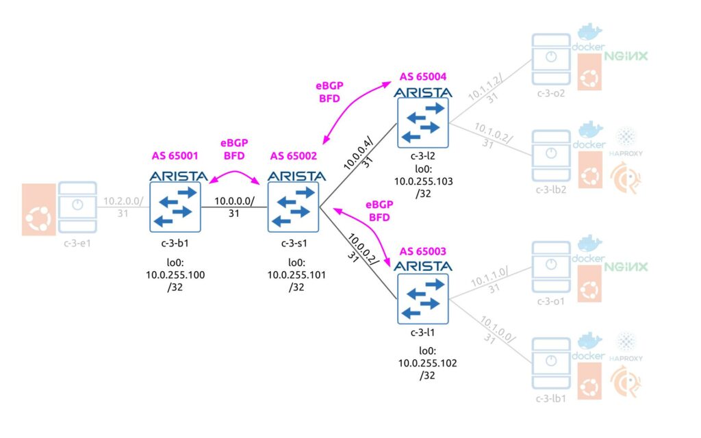
Following the aforementioned RFCs we have:
- All border leafs share the same BGP AS number
- All spines per pod (4 spines) share the same BGP AS number
- Each leaf has its own AS number as each of them hosts individual servers, each having /31 interconnect prefixes.
The eBGP peering is built using the interfaces’ IPv4 addresses with BFD being used to improve the convergence. From the advertisement perspective, only the Loopback 0 IP address with /32 prefix is announced from the each data center fabric switch. Here is the configuration snippet from c-3-b1 (the configuration on c-3-l1 and c-3-l2 are pretty much the same):
2
3
4
5
6
7
8
9
10
11
12
13
14
15
16
17
18
19
20
21
22
23
24
25
26
27
28
29
30
31
interface Loopback0
ip address 10.0.255.100/32
!
c-3-b1#show run interfaces ethernet 2
interface Ethernet2
no switchport
ip address 10.0.0.1/31
!
c-3-b1#show run section router bgp
router bgp 65001
router-id 10.0.255.100
neighbor PG_SPINE peer group
neighbor PG_SPINE bfd
neighbor PG_SPINE password ***
neighbor PG_SPINE send-community extended
neighbor 10.0.0.0 peer group PG_SPINE
neighbor 10.0.0.0 remote-as 65002
!
address-family evpn
neighbor PG_SPINE activate
!
address-family ipv4
neighbor PG_SPINE activate
network 10.0.255.100/32
!
!
The full configuration is provided in the end of the blogpost.
We don’t specify the parameters of BFD session as they are platform specific (this snippet is taken from Arista vEOS switches, which has certain limitations in terms of how low the timers can be).
Also you may see that we enable EVPN from the beginning, as we will use it later. However, for EVPN to work correctly, you need to send a number of extended communities. Therefore, we enable the exchange of the extended communities for the fabric BGP sessions.
On the spine, the configuration is very similar to leafs/borders with the small amendment: you need to disable the next-hop change for the EVPN address family to maintain the original VTEP IP as an endpoint for EVPN routes:
2
3
4
5
6
7
8
9
10
11
12
13
14
15
16
17
18
19
20
21
router bgp 65002
router-id 10.0.255.101
neighbor PG_LEAF peer group
neighbor PG_LEAF bfd
neighbor PG_LEAF password ***
neighbor PG_LEAF send-community extended
neighbor 10.0.0.1 peer group PG_LEAF
neighbor 10.0.0.1 remote-as 65001
neighbor 10.0.0.3 peer group PG_LEAF
neighbor 10.0.0.3 remote-as 65003
neighbor 10.0.0.5 peer group PG_LEAF
neighbor 10.0.0.5 remote-as 65004
!
address-family evpn
neighbor PG_LEAF activate
neighbor PG_LEAF next-hop-unchanged
!
address-family ipv4
neighbor PG_LEAF activate
network 10.0.255.101/32
Overlay configuration is completed. You can check the content of the BGP neighbors and content of the routing table to ensure it works correctly:
2
3
4
5
6
7
8
9
10
11
12
13
14
15
16
17
18
19
20
21
22
23
24
25
26
27
28
29
BGP summary information for VRF default
Router identifier 10.0.255.100, local AS number 65001
Neighbor Status Codes: m - Under maintenance
Neighbor V AS MsgRcvd MsgSent InQ OutQ Up/Down State PfxRcd PfxAcc
10.0.0.0 4 65002 428 423 0 0 05:53:10 Estab 3 3
c-3-b1#show ip route
VRF: default
Codes: C - connected, S - static, K - kernel,
O - OSPF, IA - OSPF inter area, E1 - OSPF external type 1,
E2 - OSPF external type 2, N1 - OSPF NSSA external type 1,
N2 - OSPF NSSA external type2, B - BGP, B I - iBGP, B E - eBGP,
R - RIP, I L1 - IS-IS level 1, I L2 - IS-IS level 2,
O3 - OSPFv3, A B - BGP Aggregate, A O - OSPF Summary,
NG - Nexthop Group Static Route, V - VXLAN Control Service,
DH - DHCP client installed default route, M - Martian,
DP - Dynamic Policy Route, L - VRF Leaked,
RC - Route Cache Route
Gateway of last resort is not set
C 10.0.0.0/31 is directly connected, Ethernet2
C 10.0.255.100/32 is directly connected, Loopback0
B E 10.0.255.101/32 [200/0] via 10.0.0.0, Ethernet2
B E 10.0.255.102/32 [200/0] via 10.0.0.0, Ethernet2
B E 10.0.255.103/32 [200/0] via 10.0.0.0, Ethernet2
Step #1.2. EVPN/VXLAN Overlay on Arista EOS
The next step is to get overlay up and running. Four our use case we have designed a dedicated VRF, which hosts the application. This VRF is to be configured on leafs and exits with the same Route Distinguisher (RD) and Route Targets (RT). It is also possible to use different RDs (one per leaf/border), but this is not needed in our scenario.
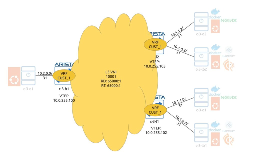
In our scenario we redistribute interconnect /31 interfaces in BGP so that data center fabric device can know in every point in time where the destination server is connected. The redistribution is controlled by the route-map, which relies on IP prefix-lists for prefix selection. There is a L3 VNI associated with this VRF, which is then mapped to a VTEP.
The following snippet is configured on the c-3-b1 and covers all the mentioned configuration elements (c-3-l1/2 have the very same configuration):
2
3
4
5
6
7
8
9
10
11
12
13
14
15
16
17
18
19
20
21
22
23
24
25
26
27
28
29
30
31
32
33
34
interface Ethernet1
no switchport
vrf CUST_1
ip address 10.2.0.0/31
!
c-3-b1#show run interfaces vxlan 1
interface Vxlan1
vxlan source-interface Loopback0
vxlan udp-port 4789
vxlan vrf CUST_1 vni 10001
!
c-3-b1#show run section ip prefix-list
ip prefix-list PL_IPV4_CUSTOMER_PREFIXES seq 10 deny 10.0.0.0/16 le 32
ip prefix-list PL_IPV4_CUSTOMER_PREFIXES seq 20 permit 10.0.0.0/8 le 32
!
c-3-b1#show run section route-map
route-map RP_IPV4_CUSTOMER_PREFIXES permit 10
match ip address prefix-list PL_IPV4_CUSTOMER_PREFIXES
route-map RP_IPV4_CUSTOMER_PREFIXES deny 9999
!
c-3-b1#show run section router bgp
router bgp 65001
vrf CUST_1
rd 65000:1
route-target import evpn 65000:1
route-target export 65000:1
route-target export evpn 65000:1
redistribute connected route-map RP_IPV4_CUSTOMER_PREFIXES
!
Spine c-3-s1 doesn’t have VTEP as it doesn’t terminate neither originate the customer’s traffic. Hence, there is no extra BGP configuration needed either.
If everything was configured correctly, you shall see interconnecting subnets being correctly distributes across leafs and border and installed in the routing table inside the VRF:
2
3
4
5
6
7
8
9
10
11
12
13
14
15
16
17
18
19
20
21
VRF: CUST_1
Codes: C - connected, S - static, K - kernel,
O - OSPF, IA - OSPF inter area, E1 - OSPF external type 1,
E2 - OSPF external type 2, N1 - OSPF NSSA external type 1,
N2 - OSPF NSSA external type2, B - BGP, B I - iBGP, B E - eBGP,
R - RIP, I L1 - IS-IS level 1, I L2 - IS-IS level 2,
O3 - OSPFv3, A B - BGP Aggregate, A O - OSPF Summary,
NG - Nexthop Group Static Route, V - VXLAN Control Service,
DH - DHCP client installed default route, M - Martian,
DP - Dynamic Policy Route, L - VRF Leaked,
RC - Route Cache Route
Gateway of last resort is not set
B E 10.1.0.0/31 [200/0] via VTEP 10.0.255.102 VNI 10001 router-mac 4a:be:91:df:4f:91
B E 10.1.0.2/31 [200/0] via VTEP 10.0.255.103 VNI 10001 router-mac 12:c5:a5:ed:70:ab
B E 10.1.1.0/31 [200/0] via VTEP 10.0.255.102 VNI 10001 router-mac 4a:be:91:df:4f:91
B E 10.1.1.2/31 [200/0] via VTEP 10.0.255.103 VNI 10001 router-mac 12:c5:a5:ed:70:ab
C 10.2.0.0/31 is directly connected, Ethernet1
The only piece which is not yet covered in this configuration is the configuration of BGP peering between the load balancer and leafs. It will be covered in the load balancer part later in this blogpost. Besides that, the multi-tenant EVPN/VXLAN data center fabric based on Arista EOS is ready to serve the traffic.
Step #2. Origin Web Servers
The next step is to bring up the origin web servers, which actually will serve the clients’ requests.
Step #2.1. Containerization Engine with Docker
The webserver, as well as the load balancer, is in our opinion great services to be containerized. There is a number of operational benefits to do so, including the following among others:
- Removing dependencies between the application’s runtime and infrastructure host.
- Simplifying application packaging and versioning.
- Improving user experience in the application management.
For the containerization engine we choose Docker, as this is one of the most stable and mature products for such a purpose on the market.
If you are not familiar with Docker but thrive to learn more, enroll to our zero-to-hero network automation training, where you will learn Docker details and even will create your own containerized applications.
All our servers, which we use both for load balancers and for origin web servers run Ubuntu Linux 22.04. As such, we follow the official guide how to install Docker Engine in Ubuntu Linux:
2
3
4
5
6
7
8
9
10
11
12
13
14
15
16
17
18
19
$ sudo apt-get install \
ca-certificates \
curl \
gnupg \
lsb-release -y
$ sudo mkdir -p /etc/apt/keyrings
$ curl -fsSL https://download.docker.com/linux/ubuntu/gpg | sudo gpg --dearmor -o /etc/apt/keyrings/docker.gpg
$ echo \
"deb [arch=$(dpkg --print-architecture) signed-by=/etc/apt/keyrings/docker.gpg] https://download.docker.com/linux/ubuntu \
$(lsb_release -cs) stable" | sudo tee /etc/apt/sources.list.d/docker.list > /dev/null
$ sudo apt-get update -y
$ sudo apt-get install docker-ce docker-ce-cli containerd.io docker-compose-plugin -y
If all is done accurately, you shall be able to see the Docker service up and running:
2
3
4
5
6
7
8
9
10
11
12
13
14
15
16
17
18
19
20
21
22
23
24
25
26
27
28
29
30
31
32
33
34
35
36
37
38
39
40
41
42
43
44
45
46
47
48
49
50
51
52
53
54
55
56
57
Client:
Context: default
Debug Mode: false
Plugins:
app: Docker App (Docker Inc., v0.9.1-beta3)
buildx: Docker Buildx (Docker Inc., v0.8.2-docker)
compose: Docker Compose (Docker Inc., v2.6.0)
scan: Docker Scan (Docker Inc., v0.17.0)
Server:
Containers: 0
Running: 0
Paused: 0
Stopped: 0
Images: 0
Server Version: 20.10.17
Storage Driver: overlay2
Backing Filesystem: extfs
Supports d_type: true
Native Overlay Diff: true
userxattr: false
Logging Driver: json-file
Cgroup Driver: systemd
Cgroup Version: 2
Plugins:
Volume: local
Network: bridge host ipvlan macvlan null overlay
Log: awslogs fluentd gcplogs gelf journald json-file local logentries splunk syslog
Swarm: inactive
Runtimes: io.containerd.runc.v2 io.containerd.runtime.v1.linux runc
Default Runtime: runc
Init Binary: docker-init
containerd version: 10c12954828e7c7c9b6e0ea9b0c02b01407d3ae1
runc version: v1.1.2-0-ga916309
init version: de40ad0
Security Options:
apparmor
seccomp
Profile: default
cgroupns
Kernel Version: 5.15.0-46-generic
Operating System: Ubuntu 22.04.1 LTS
OSType: linux
Architecture: x86_64
CPUs: 2
Total Memory: 3.832GiB
Name: c-3-o1
ID: FTU2:ZPIC:ZATK:I5VE:CYIU:HZUW:X4VV:EDPU:3A7N:OF2T:SR65:3JLA
Docker Root Dir: /var/lib/docker
Debug Mode: false
Registry: https://index.docker.io/v1/
Labels:
Experimental: false
Insecure Registries:
127.0.0.0/8
Live Restore Enabled: false
In the latest docker version we use, docker compose is installed automatically as a plugin to docker CLI and is executed as “sudo docker compose” instead of old syntax “sudo docker-compose“.
Step #2.2. Origin Web Server with NGINX
For the application, which acts as an origin web server, we are using NGINX per the details shared in the previous blogpost. To get it up and running, need just three files:
- HTML static file, which will be used a user content.
- Configuration file for the NGINX itself.
- Docker-compose file to describe the containerized service.
The directory’s structure looks as follows and it contains the aforementioned three files distributed across 2 sub-directories:
2
3
4
5
6
+--config
| +--karneliuk_service.conf
+--content
| +--index.html
+--docker-compose.yaml
The service description file is really simply one:
2
3
4
5
6
7
8
9
10
11
server {
listen 80;
listen [::]:80;
server_name localhost;
location / {
root /tmp/content;
index index.html index.htm;
}
}
As you see, we instruct the NGINX service to listen to the port 80 and to serve the file index.html or index.htm (first attempt the former and then the latter) from the directory /tmp/content. Don’t worry that we serve here unencrypted content, our load balancer is terminating the SSL session from customers. This is a common deployment design for online applications, as it allows to spare compute the resources on origin web servers as the encryption/decryption is done outside of them.
You may think, “How does NGINX know that it shall pickup config from karneliuk_service.conf file as its name looks very specific?” We’ll get back to this question shortly. Let’s take a look at two other files we have used at our origin server:
2
3
4
5
6
7
8
9
10
11
12
13
14
15
16
17
<html>
<head>
<title>Best Automation Trainings at Karneliuk.com</title>
</head>
<body>
<h1>Test worker</h1>
<p>Enroll to <a href="http://training.karneliuk.com/">Network Automation Trainings</a>.</p>
<p>For online documentation and support please refer to
<a href="http://nginx.org/">nginx.org</a>.<br/>
Commercial support is available at
<a href="http://nginx.com/">nginx.com</a>.</p>
<p><em>Thank you for using nginx.</em></p>
</body>
</html>
As you can see this is static HTML file, which is not altered during being served to a customer.
Finally, the docker-compose.yaml:
2
3
4
5
6
7
8
9
10
11
12
13
---
version: "3.9"
services:
web:
image: nginx
restart: always
ports:
- 8080:80
volumes:
- ./config:/etc/nginx/conf.d
- ./content:/tmp/content
...
If you are familiar with Docker, you can see that the container is supposed be like this:
- It runs the official nginx image
- It maps the external port 8080 to internal 80. It means that traffic shall arrive to the origin server to the destination port 8080/tcp and it will translated to port 80/tcp on the origin server
- the container shall be up all the time unless we manually bring it down.
- There are two folders from the local server mapped to the corresponding directories inside the container.
Join our Zero-to-Hero Network Automation Training to learn more about Docker and master skills of building your own containerized applications.
Coming back to the question we put above, “How does NGINX know about the config file?” As you could digest from the docker-compose.yaml, we map the directory with our configuration file from the Ubuntu host to the directory /etc/nginx/conf.d inside the container. By default NGINX is looking for the config files there and as long as they follow the correct syntax, it will try use it. That’s the answer.
Once the aforementioned files are created and put in the corresponding folders’ structure, we can launch the container with the origin server:
2
(nginx)$ sudo docker-compose.yaml
Wait until the download of the image is completed and the container is started. Once that is done, you shall see it up and running:
2
3
CONTAINER ID IMAGE COMMAND CREATED STATUS PORTS NAMES
39dde6252478 nginx "/docker-entrypoint.…" 13 days ago Up 5 days 0.0.0.0:8080->80/tcp, :::8080->80/tcp nginx-web-1
The final validation step is to check if we can actually query the website. For this purpose we use curl, which is a tool built in on almost all Linux distributions by default (or you can install it). We run this request directly from the server, which has NGINX up and running:
2
3
4
5
6
7
8
9
10
11
12
13
14
15
16
<html>
<head>
<title>Best Automation Trainings at Karneliuk.com</title>
</head>
<body>
<h1>Test worker</h1>
<p>Enroll to <a href="http://training.karneliuk.com/">Network Automation Trainings</a>.</p>
<p>For online documentation and support please refer to
<a href="http://nginx.org/">nginx.org</a>.<br/>
Commercial support is available at
<a href="http://nginx.com/">nginx.com</a>.</p>
<p><em>Thank you for using nginx.</em></p>
</body>
The origin web service is up and running correctly, so we can move the load balancer part.
Step #3. Open Source Load Balancer
The load balancer is key component in this solution and in general in application delivery to customers in a reliable fashion. It consists of two main parts:
- Routing, which in this case is performed with FRR
- Load balancing, which in this case is performed by HA Proxy
Step #3.1. Containerization Engine with Docker
Repeat the step 2.1 on the Linux servers, which will host HAProxy and FRR , to have Docker up and running.
Step #3.2. Routing Engine with FRR
There are two ways how you can implement FRR on the server, depending on how you want it to act:
- Install it on the underlying Linux host as daemon. In this case FRR will be able to alter the routing table of the Linux host. In multiple cases it can be a desired outcome, especially when your Linux host is connected to multiple networks and perform routing indeed.
- Install it as a container. In this case the FRR is not able to alter the routing table of the Linux host; however, it still is able to announce prefixes via routing protocols (e.g. BGP) so that they are available to the rest parts of the network.
If you analyze our topology carefully, you will see that the load balancer is in fact one-armed: it is connected to the network with just one interface, over single interconnect subnet, which is used to reach default gateway. In such a case, we don’t really need to modify the routing table of the underlying Linux host and, therefore, we decided to run FRR containerized.
To do that, we need to create the corresponding directory and place the docker-compose.yaml file there:
2
+--docker-compose.yaml
The docker-compose.yaml looks as follows:
2
3
4
5
6
7
8
9
10
11
12
13
14
15
16
---
version: "3.9"
services:
frr:
image: frrouting/frr
network_mode: host
restart: always
volumes:
- frr_config:/etc/frr
privileged: true
volumes:
frr_config:
driver: local
...
In order to store the configuration persistently, we create a local drive, which will store the configuration file of the FRR application and routing daemons.
Start the container:
2
$ sudo docker compose up -d
Check that is successfully up and running:
2
3
4
[sudo] password for aaa:
CONTAINER ID IMAGE COMMAND CREATED STATUS PORTS NAMES
913377c8d65e frrouting/frr "/sbin/tini -- /usr/…" 13 days ago Up 5 days frr-frr-1
The configuration of FRR is split in to major parts:
- daemons, which needs to be enabled for some functionality to work.
- configuration applied to the corresponding daemons.
In our case we need to have 2 daemons: BGP and BFD. BGP is needed to announce the VIP address to the network, and BFD is needed to quickly turn down the BGP session and, as a result, to remove the VIP from the data center fabric.
We enable the daemons by modifying the configuration files inside the persistent docker storage:
2
$ sudo sed -i 's/bfdd=no/bfdd=yes/' /var/lib/docker/volumes/frr_frr_config/_data/daemons
The one could say that this is an anti-pattern for the containerized applications: however, it does the job perfectly in our case.
Once the daemons are enabled, you would need to restart the Docker application:
Finally, you can configure the FRR application:
2
3
4
5
6
7
8
9
10
11
12
13
14
15
16
17
18
19
20
21
22
23
24
25
26
27
28
29
30
31
32
33
34
!
! Config is done inside FRR application inside the container
!
configure terminal
ip prefix-list PL_IPV4_VIP seq 10 permit 10.1.0.254/32
!
route-map RP_IPV4_ADVERTISE_VIP permit 10
match ip address prefix-list PL_IPV4_VIP
!
route-map RP_IPV4_ADVERTISE_VIP deny 9999
!
ip prefix-list PL_IPV4_DEF_ROUTE seq 10 permit 0.0.0.0/0
!
route-map RP_IPV4_RECIEVE_DEF permit 10
match ip address prefix-list PL_IPV4_DEF_ROUTE
!
route-map RP_IPV4_RECIEVE_DEF deny 9999
!
router bgp 65100
bgp router-id 10.1.0.1
bgp log-neighbor-changes
!
neighbor 10.1.0.0 remote-as 65003
neighbor 10.1.0.0 bfd
!
address-family ipv4 unicast
network 10.1.0.254/32
!
neighbor 10.1.0.0 activate
neighbor 10.1.0.0 route-map RP_IPV4_ADVERTISE_VIP out
neighbor 10.1.0.0 route-map RP_IPV4_RECIEVE_DEF in
!
!
Once the configuration is done, don’t forget to save the config:
As you can see, the configuration of FRR is very similar to the one you’ve done via CLI, something that is called these days as a “industry CLI“.
On the second load balancer, we would add AS_PATH prepending to the route map, which is controlling announcement to the fabric, to control ourselves on which load balancer the traffic be sent. Such an approach permits us to have per VIP granularity, so that we can use one LB as a primary for one VIP and another for another VIP:
2
3
4
5
6
7
8
!
route-map RP_IPV4_ADVERTISE_VIP permit 10
match ip address prefix-list PL_IPV4_VIP
set as-path prepend 65100 65100 65100 65100 65100
!
!
! CONFIGURATION IS TRUNCATED FOR BREVITY
The rest configuration is identical.
Once you have created configuration for routing from the load balancer side, you should create one on the data center leafs as well. Here is the example for c-3-l1 (for c-3-l2 it will be the same, just IP address will be different):
2
3
4
5
6
7
8
9
10
11
12
13
14
!
configure terminal
router bgp 65003
vrf CUST_1
neighbor 10.1.0.1 remote-as 65100
!
address-family ipv4
neighbor 10.1.0.1 activate
neighbor 10.1.0.1 default-originate always
!
!
!
!
You may need to disable checksum offload “sudo ethtool -K ens19 tx off rx off” on load balancers, where ens19 is a name of the interface towards DC fabric.
If everything has been done correctly you should be able to see the BGP session up:
2
3
4
5
6
BGP summary information for VRF CUST_1
Router identifier 10.1.1.0, local AS number 65003
Neighbor Status Codes: m - Under maintenance
Neighbor V AS MsgRcvd MsgSent InQ OutQ Up/Down State PfxRcd PfxAcc
10.1.0.1 4 65100 174257 204606 0 0 5d23h Estab 1 1
Step #3.3. Load Balancing with HAProxy
Final piece is to make the configuration of the HAProxy. As the FRR, we will run it containerized. To do that, we create the following hierarchy of directories:
2
3
4
5
6
7
8
+--config
| +--haproxy.cfg
+--ssl
| +--key.pem
| +--cert.pem
| +--joined.pem
+--docker-compose.yaml
First of all, let’s generate the self-signed certificate, which we will use to terminate the customer connectivity:
2
3
$ openssl req -x509 -newkey rsa:4096 -keyout haproxy/ssl/key.pem -out haproxy/ssl/cert.pem -sha256 -days 365 -nodes -subj '/CN=test-website.lab.karneliuk.com'
cat ssl/cert.pem ssl/key.pem > ssl/joined.pem
HAProxy requires the key and the certificate to be in the same file; as such, we simply merger them:
The last file you will attach to the frontend configuration of the load balancer.
The next part is the configuration of load balancer:
2
3
4
5
6
7
8
9
10
11
12
13
14
15
16
17
18
19
20
21
22
23
24
25
26
27
28
29
30
31
32
33
global
maxconn 4096
log /dev/log local0
defaults
timeout connect 5s
timeout client 30s
timeout server 30s
retries 3
log global
mode http
option httplog
maxconn 3000
frontend webservers_vip
bind 10.1.0.254:8080
bind 10.1.0.254:8443 ssl crt /etc/ssl/joined.pem
http-request redirect location https://10.1.0.254:8443 unless { ssl_fc }
default_backend webservers_origin
peers sticktables
bind :10000
server c-3-lb1
server c-3-lb2 10.1.0.3:10000
table sticky-sessions type ip size 1m
backend webservers_origin
balance roundrobin
stick match src table sticktables/sticky-sessions
stick store-request src table sticktables/sticky-sessions
server c-3-o1 10.1.1.1:8080 check
server c-3-o2 10.1.1.3:8080 check
The configuration of the load balancer consits of several parts, but at a high level the following three are of particular interest:
- frontend contains the VIP part, listened ports, mapping it to SSL certificate and redirection rules from HTTP to HTTPS. You also specify here what backend is used to send the traffic to.
- backend contains the defitions of the servers, which attracts the traffic as well as well as the load balancing mechanism and, in our case, stickiness configuration.
- peers specify how to reach other load balancers in the multi-active cluster to syncronise the state of the sessions. That is needed for the failover scenario to ensure that the standby load balancer will send customer’s session to exactly the same backend node (web origin server) as a primary one.
Finally, the docker-compose file:
2
3
4
5
6
7
8
9
10
11
12
---
version: "3.9"
services:
haproxy:
image: haproxy
restart: always
network_mode: host
volumes:
- ./config/haproxy.cfg:/usr/local/etc/haproxy/haproxy.cfg:ro
- ./ssl:/etc/ssl
...
Join our Zero-to-Hero Network Automation Training to master Docker skills
Launch the docker container:
And check that it is up and running:
2
3
4
[sudo] password for aaa:
CONTAINER ID IMAGE COMMAND CREATED STATUS PORTS NAMES
141815a9029a haproxy "docker-entrypoint.s…" 3 hours ago Up 2 hours haproxy-haproxy-1
Congratulations. You have made it till the end of the configuration and can check now how the whole solution is working.
Validation
The ultimate success criteria for the whols solution is to check, wether you can reach from the host c-3-e1 the origin server via load balancer. In other words, we are checking that:
- the load balancer is reachable over the network
- the origin web server is reachable via the network
- the load balancer terminates SSL sessions
- the load balancer sends the customer request to the origin web server
Step #1. Normal operation
The validation can be very simple: just hit curl towards the VIP and port (use -k key to skip the validation of the SSL certificates, which would fail for the self-signed certificates anyway):
2
3
4
5
6
7
8
9
10
11
12
13
14
15
16
17
<html>
<head>
<title>Best Automation Trainings at Karneliuk.com</title>
</head>
<body>
<h1>Test worker</h1>
<p>Enroll to <a href="http://training.karneliuk.com/">Network Automation Trainings</a>.</p>
<p>For online documentation and support please refer to
<a href="http://nginx.org/">nginx.org</a>.<br/>
Commercial support is available at
<a href="http://nginx.com/">nginx.com</a>.</p>
<p><em>Thank you for using nginx.</em></p>
</body>
</html>
You can also check if the redirect is working:
2
3
4
5
6
7
8
9
10
11
12
13
14
15
16
17
<html>
<head>
<title>Best Automation Trainings at Karneliuk.com</title>
</head>
<body>
<h1>Test worker</h1>
<p>Enroll to <a href="http://training.karneliuk.com/">Network Automation Trainings</a>.</p>
<p>For online documentation and support please refer to
<a href="http://nginx.org/">nginx.org</a>.<br/>
Commercial support is available at
<a href="http://nginx.com/">nginx.com</a>.</p>
<p><em>Thank you for using nginx.</em></p>
</body>
</html>
As you see, you need to add also the “-L” key as by default the curl doesn’t follow the redirect.
To see that the load balancer is actually working in a sticky mode, we will do the following amendment: in the static html file we have created before we will add a some info about the origin webserver, so that in the respones we can see where it comes from:
2
3
4
5
6
7
8
9
10
11
<head>
<title>Best Automation Trainings at Karneliuk.com</title>
</head>
<body>
<h1>Test worker</h1>
<p>Enroll to <a href="http://training.karneliuk.com/">Network Automation Trainings</a>.</p>
<p><strong>origin server 1</strong></p>
<p><em>Thank you for using nginx.</em></p>
</body>
</html>
Same amendment we’ll do on the second server. We don’t need to restart the Docker container with NGINX, the files are stored on the Linux server, not inside the container.
So if we do multiple reuquests now, you see that all of them are landed to the same server:
2
3
4
5
6
7
8
9
10
11
12
13
14
15
16
17
18
19
20
21
22
23
24
25
26
27
28
29
30
31
32
33
34
35
36
37
38
<html>
<head>
<title>Best Automation Trainings at Karneliuk.com</title>
</head>
<body>
<h1>Test worker</h1>
<p>Enroll to <a href="http://training.karneliuk.com/">Network Automation Trainings</a>.</p>
<p>origin server 2</p>
<p><em>Thank you for using nginx.</em></p>
</body>
</html>
c-3-e1$ curl -X GET https://10.1.0.254:8443 -k -L
<html>
<head>
<title>Best Automation Trainings at Karneliuk.com</title>
</head>
<body>
<h1>Test worker</h1>
<p>Enroll to <a href="http://training.karneliuk.com/">Network Automation Trainings</a>.</p>
<p>origin server 2</p>
<p><em>Thank you for using nginx.</em></p>
</body>
</html>
This is the confirmation that the stickiness is working. Otherwise, as the load balancing mechanism is round-robin, all the requests will be placed to the same server.
Step #2. Failover
Before tesing failolver, let’s check the status of the routing table inside the VRF at our border leaf:
2
3
4
5
6
7
8
9
10
11
12
13
14
15
16
17
18
19
20
21
22
VRF: CUST_1
Codes: C - connected, S - static, K - kernel,
O - OSPF, IA - OSPF inter area, E1 - OSPF external type 1,
E2 - OSPF external type 2, N1 - OSPF NSSA external type 1,
N2 - OSPF NSSA external type2, B - BGP, B I - iBGP, B E - eBGP,
R - RIP, I L1 - IS-IS level 1, I L2 - IS-IS level 2,
O3 - OSPFv3, A B - BGP Aggregate, A O - OSPF Summary,
NG - Nexthop Group Static Route, V - VXLAN Control Service,
DH - DHCP client installed default route, M - Martian,
DP - Dynamic Policy Route, L - VRF Leaked,
RC - Route Cache Route
Gateway of last resort is not set
B E 10.1.0.0/31 [200/0] via VTEP 10.0.255.102 VNI 10001 router-mac 4a:be:91:df:4f:91
B E 10.1.0.2/31 [200/0] via VTEP 10.0.255.103 VNI 10001 router-mac 12:c5:a5:ed:70:ab
B E 10.1.0.254/32 [200/0] via VTEP 10.0.255.102 VNI 10001 router-mac 4a:be:91:df:4f:91
B E 10.1.1.0/31 [200/0] via VTEP 10.0.255.102 VNI 10001 router-mac 4a:be:91:df:4f:91
B E 10.1.1.2/31 [200/0] via VTEP 10.0.255.103 VNI 10001 router-mac 12:c5:a5:ed:70:ab
C 10.2.0.0/31 is directly connected, Ethernet1
You can see that VIP is reachable via next-hop 10.0.255.102, which is a loopback IP used for VTEP at c-3-l1. Now, let’s disable the port from c-3-l1 towards the load balancer, which will terminate the BGP session and shall cause re-routing. Thanks to BFD, it will be quick:
2
3
4
c-3-l1(config)#int eth2
c-3-l1(config-if-Et2)#shut
c-3-l1(config-if-Et2)#Sep 4 12:07:07 c-3-l1 Bgp: %BGP-3-NOTIFICATION: sent to neighbor 10.1.0.1 (VRF CUST_1 AS 65100) 6/6 (Cease/other configuration change) 0 bytes
As soon as this happens, you shall be able to see the backup route availble to VIP:
2
3
4
5
6
7
8
9
10
11
12
13
14
15
16
17
18
19
20
21
VRF: CUST_1
Codes: C - connected, S - static, K - kernel,
O - OSPF, IA - OSPF inter area, E1 - OSPF external type 1,
E2 - OSPF external type 2, N1 - OSPF NSSA external type 1,
N2 - OSPF NSSA external type2, B - BGP, B I - iBGP, B E - eBGP,
R - RIP, I L1 - IS-IS level 1, I L2 - IS-IS level 2,
O3 - OSPFv3, A B - BGP Aggregate, A O - OSPF Summary,
NG - Nexthop Group Static Route, V - VXLAN Control Service,
DH - DHCP client installed default route, M - Martian,
DP - Dynamic Policy Route, L - VRF Leaked,
RC - Route Cache Route
Gateway of last resort is not set
B E 10.1.0.2/31 [200/0] via VTEP 10.0.255.103 VNI 10001 router-mac 12:c5:a5:ed:70:ab
B E 10.1.0.254/32 [200/0] via VTEP 10.0.255.103 VNI 10001 router-mac 12:c5:a5:ed:70:ab
B E 10.1.1.0/31 [200/0] via VTEP 10.0.255.102 VNI 10001 router-mac 4a:be:91:df:4f:91
B E 10.1.1.2/31 [200/0] via VTEP 10.0.255.103 VNI 10001 router-mac 12:c5:a5:ed:70:ab
C 10.2.0.0/31 is directly connected, Ethernet1
Which is pointing towards the VTEP at c-3-l2.
Now repeat request from the c-3-e1:
2
3
4
5
6
7
8
9
10
11
12
<html>
<head>
<title>Best Automation Trainings at Karneliuk.com</title>
</head>
<body>
<h1>Test worker</h1>
<p>Enroll to <a href="http://training.karneliuk.com/">Network Automation Trainings</a>.</p>
<p>origin server 2</p>
<p><em>Thank you for using nginx.</em></p>
</body>
</html>
You see that request is landing on the same server.
GitHub repository
You can find all the configuration files in our GitHub repo.
Lessons Learned
The biggest learning curve for us was about the HAProxy itself. Being very popular and powerfull tool, its documentation in many cases is relatively complicated. As such, we had to go through many different sources in order to hash out together all the descriptions to be able to build a working solution. However, as usual, the harder you study, the easier is in production.
Summary
The blogpots appered to be somewhat lengthy and contained a lot of configurations from different areas. At the same time, it shows the real complexity of the application delivery networks, not even touching TCP optimisation or caching. The important point here is that you can achieve really good, stable, and feature reach network solution leveraging solely Open Source components. We truly believe that HAProxy + FRR bundly is very strong one, as it allows to achieve load balancing without the need to stretch nasty L2 segments even within the data centre. Reach us out if you have any questions about the solution. Take care and good bye.
Need Help? Contract Us
If you need a trusted and experienced partner to automate your network and IT infrastructure, get in touch with us.
P.S.
If you have further questions or you need help with your networks, we are happy to assist you, just send us a message. Also don’t forget to share the article on your social media, if you like it.
BR,
Anton Karneliuk