Site icon Karneliuk

Configuring OSPF between Nokia (Alcatel-Lucent) SR OS and Cisco IOS XR

Hello my friend,
This article will be quite long so make a cup of tea for you sit more comfortable. Though the configuration of any routing protocol (IGP) can be relatively quick and short, usually you have to tune many additional parameters to get desired level of speed and reliability. I won’t cover all the features of OSPF, as it’s just impossible, but I will provide more or less complete config, which is used in service provider network.

Topology

In previous articles we have used only one physical interface between our Nokia (Alcatel-Lucent) VSR (SR 7750) and Cisco IOS XRv. In the article about trunking I’ve shown how to configure trunk and sub interfaces between (Alcatel-Lucent) VSR (SR 7750) and Cisco IOS XRv, therefore it’s possible to create multiple logical interfaces which is useful for description of IGP’s work. Nevertheless in this article we’ll add one more physical link (if it’s possible to say so about fully virtual environment) between our SR1 and XR1, so our “physical” topology for the current lab is:

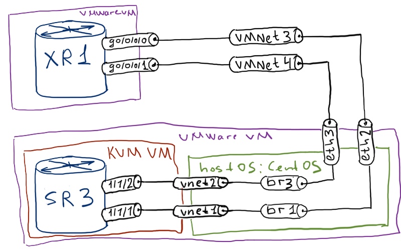
If you have forgotten how to do it or this article is the first one you read from my series, take a look to the first one for guidelines how to create additional link.
The next step is to create the logical topology for our lab. It isn’t very complex, though it provides us possibility to configure a lot of features:

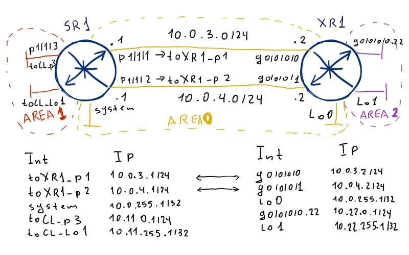
Later I’ll add one interface to each router in order to configure redistribution. They aren’t shown at the image below in order not to mix them with area structure. Initial configuration of Nokia (Alcatel-Lucent) VSR (SR 7750) and Cisco IOS XR (ASR 9000) routers you can find here: SR1 and XR1.

Basic intra-area connectivity with not basic parameters

As usual I assume that you have understanding of OSPF’s operation.

First of let’s establish connectivity between SR1 and XR1. As you know, there are two main types of network (or interface, how it’s called in Nokia (Alcatel-Lucent) SR OS), which define whether the Designated Router (DR) is used or not. Let’s briefly compare available options:

Nokia (Alcatel-Lucent) SR OS Cisco IOS XR (IOS XE, NX-OS)
Broadcast – all routers send multicast packets to discover each other/maintain adjacency. DR/BDR is chosen
Point-to-point – only two neighbors are possible at interface. Multicast packets are sent to discover each other/maintain adjacency. There is no DR/BDR
Broadcast – all routers send multicast packets to discover each other/maintain adjacency. DR/BDR is chosen
Point-to-point – only two neighbors are possible at interface. Multicast packets are sent to discover each other/maintain adjacency. There is no DR/BDR
Nonbroadcast – static OSPF neighbors must be configured, unicast packets are sent then to establish/keep adjacency and exchange LSAs. DR/BDR is chosen
Point-to-multipoint – Multiple neighbors in subnet though they establish adjacency only with central router (hub). Multicast packets are sent to discover each other/maintain adjacency. There is no DR/BDR
Point-to-multipoint nonboradcast – Multiple neighbors in subnet though they establish adjacency only with central router (hub). Static OSPF neighbors must be configured, unicast packets are sent then to establish/keep adjacency and exchange LSAs. There is no DR/BDR
Loopback – special type for loopback interfaces. No packets are sent, and prefix is always advertised as /32 despite of actually configured at interface

For non broadcast interfaces Cisco IOS / IOS XR demands the configuration of static OSPF neighbor at least of one side of link. In Nokia (Alcatel-Lucent) SR OS I haven’t found such possibility.

In modern network only point-to-point and broadcast network types are used. The first type is usually used to interconnect routers with each other; whereas the latter one is used for connecting customer devices (i.E Radio Network Controller (RNC) in service provider network). In our lab we’ll configure both these types of networks in the following way:

Interface type SR1 – Nokia VSR XR1 – Cisco IOS XRv
broadcast toXR1_p1 g0/0/0/0
point-to-point toXR1_p2 g0/0/0/1


To see OSPF work in real time additional logging is configured at Nokia (Alcatel-Lucent) SR OS.

Let’s start the configuration our Nokia (Alcatel-Lucent) VSR (SR 7750) and Cisco IOS XRv (ASR 9000):

SR1 – Nokia (Alcatel-Lucent) VSR (SR 7750) XR1 – Cisco IOS XRv (ASR 9000)

A:SR1>config>router# ospf 1
A:SR1>config>router>ospf# info
————————————-
no shutdown
router-id 10.0.255.1
area 0.0.0.0
interface “system”
no shutdown
exit
interface “toXR1_p1”
interface-type broadcast
hello-interval 2
dead-interval 8
authentication-type message-digest
message-digest-key 1 md5 N0K1@
no shutdown
exit
interface “toXR1_p2”
interface-type point-to-point
hello-interval 2
dead-interval 8
authentication-type message-digest
message-digest-key 1 md5 C1$Co
no shutdown
exit
exit
————————————-

RP/0/0/CPU0:XR1(config)#show conf
router ospf CORE
router-id 10.0.255.2
area 0.0.0.0
interface Loopback0
!
interface GigabitEthernet0/0/0/0
authentication message-digest
message-digest-key 1 md5 N0K1@
network broadcast
hello-interval 2
!
interface GigabitEthernet0/0/0/1
authentication message-digest
message-digest-key 1 md5 C1$C0
network point-to-point
hello-interval 2
!
!
!
end

I guess that you have some questions to the provided configuration, so let’s discuss it a little bit. Both routers have the possibility to automatically assign router ID (RID) to OSPF configuration:

The next point is authentication. Though both routers supports plain text authentication, it isn’t secure at all and we use MD5 authentication at both interfaces.

In configuration file the password is saved and shown in encrypted form. The password is provided in clear text above is just for your reference.

The last point here is the configuration of hello/dead intervals. By default they are 10/40 seconds respectively. Here is some difference in their configuration at Nokia (Alcatel-Lucent) SR OS and Cisco IOS XR:

So far we have discussed the configuration, let’s check whether OSPF adjacency has been established:

RP/0/0/CPU0:XR1#show ospf CORE neighbor
* Indicates MADJ interface
# Indicates Neighbor awaiting BFD session up
Neighbors for OSPF CORE
Neighbor    ID Pri  State         Dead Time   Address    Interface
10.0.255.1  1  1    EXSTART/BDR   00:00:07    10.0.3.1   GigabitEthernet0/0/0/0
10.0.255.1  1  1    DOWN/ –       –           10.0.4.1   GigabitEthernet0/0/0/

Well, we see that adjacency hasn’t come up. One of interface is down, whereas the second one is stuck in EXSTART phase. Usually such stuck means that we have problem with MTU mismatch between peering routers:

SR1 – Nokia (Alcatel-Lucent) VSR (SR 7750) XR1 – Cisco IOS XRv (ASR 9000)

A:SR1# show router interface detail | match expression “Name|MTU”
If Name       : system
IP Oper MTU   : 1500
If Name       : toCL_Lo1
IP Oper MTU   : 1500
If Name       : toCL_p3
IP Oper MTU   : 8922
If Name       : toXR1_p1
IP Oper MTU   : 8922
If Name       : toXR1_p2
IP Oper MTU   : 8922

RP/0/0/CPU0:XR1#sh ipv4 interface | utility egrep “Up|MTU”
Loopback0 is Up, ipv4 protocol is Up
MTU is 1500 (1500 is available to IP)
Loopback1 is Up, ipv4 protocol is Up
MTU is 1500 (1500 is available to IP)
GigabitEthernet0/0/0/0 is Up, ipv4 protocol is Up
MTU is 1514 (1500 is available to IP)
GigabitEthernet0/0/0/0.22 is Up, ipv4 protocol is Up
MTU is 1518 (1500 is available to IP)
GigabitEthernet0/0/0/1 is Up, ipv4 protocol is Up
MTU is 1514 (1500 is available to IP)

And that is one of the cornerstones. The default MTU at Cisco IOS XR is 1514 (IP MTU 1500), whereas Nokia (Alcatel-Lucent) VSR has MTU 8936 (IP MTU is 8922):

A:SR1# show port detail
=============================================================================
Ports on Slot 1
=============================================================================
Port  Admin  Link   Port   Cfg  Oper  LAG/  Port  Port  Port  C/QS/S/XFP/
Id    State         State  MTU  MTU   Bndl  Mode  Encp  Type  MDIMDX
—————————————————————————–
1/1/1 Up     Yes    Up     8936 8936  –     netw  null  xcme  GIGE-LX 10KM
1/1/2 Up     Yes    Up     8936 8936  –     netw  null  xcme  GIGE-LX 10KM
1/1/3 Up     Yes    Up     8936 8936  –     netw  null  xcme  GIGE-LX 10KM
1/1/4 Up     No     Down   8936 8936  –     netw  null  xcme  GIGE-LX 10KM
1/1/5 Down   No     Down   8936 8936  –     netw  null  xcme  GIGE-LX 10KM
=============================================================================

We have to make them equal, so I’ll increase the MTU size at Cisco IOS XR:

RP/0/0/CPU0:XR1(config)#show conf
interface GigabitEthernet0/0/0/0
mtu 8936
!
interface GigabitEthernet0/0/0/1
mtu 8936
!
end

Just after applying the necessary changes to MTU at Cisco IOS XR, we see desired logs at both devices:

RP/0/0/CPU0:Jul 17 19:41:46.879 : ospf[1018]: %ROUTING-OSPF-5-ADJCHG : Process CORE, Nbr 10.0.255.1 on GigabitEthernet0/0/0/0 in area 0.0.0.0 from LOADING to FULL, Loading Done, vrf default vrfid 0x60000000
RP/0/0/CPU0:Jul 17 19:41:46.879 : ospf[1018]: %ROUTING-OSPF-5-ADJCHG : Process CORE, Nbr 10.0.255.1 on GigabitEthernet0/0/0/1 in area 0.0.0.0 from LOADING to FULL, Loading Done, vrf default vrfid 0x60000000
!
!
A:SR1#
46 2016/07/31 14:05:10.01 UTC WARNING: OSPF #2042 Base VR: 1 OSPFv2 (1)
“LCL_RTR_ID 10.0.255.1: Neighbor 10.0.255.2 on toXR1_p2 router state changed to full (event LOAD_DONE)”
47 2016/07/31 14:05:10.01 UTC WARNING: OSPF #2042 Base VR: 1 OSPFv2 (1)
“LCL_RTR_ID 10.0.255.1: Neighbor 10.0.255.2 on toXR1_p1 router state changed to full (event LOAD_DONE)”

It’s what we need and now we can check the routing tables (RIB) at both routers. Cisco IOS XR shows:

RP/0/0/CPU0:XR1#show route ipv4 ospf
O 10.0.255.1/32 [110/1] via 10.0.4.1, 00:02:45, GigabitEthernet0/0/0/1
[110/1] via 10.0.3.1, 00:02:45, GigabitEthernet0/0/0/0

And Nokia (Alcatel-Lucent) VSR (SR 7750) has the following RIB:

A:SR1# show router route-table protocol ospf
=============================================================================
Route Table (Router: Base)
=============================================================================
Dest Prefix[Flags]                        Type    Proto    Age       Pref
Next Hop[Interface Name]                                 Metric
—————————————————————————–
10.0.255.2/32                             Remote  OSPF(1)  00h02m35s 10
10.0.3.2                                                 101
—————————————————————————–
No. of Routes: 1

Though in both RIBs we see the necessary routes, Nokia (Alcatel-Lucent) SR OS by default has only one path to the destination, whereas Cisco IOS XR has two. The reason for that is deactivated ECMP (equal cost multipath) feature in Nokia (Alcatel-Lucent) VSR (SR 7750). So we need to activate it:

A:SR1>config>router# ecmp 2
A:SR1# show router route-table protocol ospf
=============================================================================
Route Table (Router: Base)
=============================================================================
Dest Prefix[Flags]                        Type    Proto    Age       Pref
Next Hop[Interface Name]                                 Metric
—————————————————————————–
10.0.255.2/32                             Remote  OSPF(1) 00h00m06s  10
10.0.3.2                                                 101
10.0.255.2/32                             Remote  OSPF(1) 00h00m06s  10
10.0.4.2                                                 101
—————————————————————————–
No. of Routes: 2

Now let’s align, let’s say, the vocabulary, which is used in RIB by our wonderful vendors. “Pref” (Preference) in Nokia (Alcatel-Lucent) SR OS has the same meaning as “AD” (Administrative Distance) in Cisco. It’s a local parameter, which allows choosing the same prefix across different protocols. Numerically they are different, but in general we don’t need to take care of it. We just need to check whether the same prefixes use the same protocol by Nokia (Alcatel-Lucent) SR OS and Cisco IOS XR. We’ll back to this parameter later in our article one more time.

The next important parameter is metric. At SR1 we have it with value “101” for 10.0.255.1/32 prefix, whereas at XR1 we have metric of “1” only. So huge difference is based on different reference bandwidth, which is used to calculate OSPF’s metric according to RFC 2328. According to this RFC 2328, which actually describes OSPFv2 being implemented both by Nokia (Alcatel-Lucent) and Cisco, cost of link is calculated as “10^8 / link_bw”, where “link_bw” is measured in bits per second. It means that for all interfaces with the bandwidth more than 100 Mbps, the link cost will be always 1, what is obviously not desired. Nokia (Alcatel-Lucent) doesn’t follow this RFC and uses (at least in current SR OS release) another reference metric:

A:SR1# show router ospf 1 status | match Reference
Reference Bandwidth : 100,000,000 Kbps

So instead of “10^8” the value of “10^11” is used. This parameter must be the same across all the routers in the routing domain, so we’ll change it at Cisco IOS XR:

RP/0/0/CPU0:XR1(config)#show conf
router ospf CORE
auto-cost reference-bandwidth 100000
!
end

Upon applying the configuration we see that the result is almost the same, though isn’t equal:

RP/0/0/CPU0:XR1#show route ipv4 ospf
O 10.0.255.1/32 [110/100] via 10.0.4.1, 00:00:12, GigabitEthernet0/0/0/1
[110/100] via 10.0.3.1, 00:00:12, GigabitEthernet0/0/0/0

The key to this difference can be found in LSDB (Link state database), which is the most important component of OSPF. Let’s check it at Nokia (Alcatel-Lucent) VSR (SR 7750):

A:SR1# show router ospf 1 database type router detail
=============================================================================
OSPFv2 (1) Link State Database (Type : Router) (Detailed)
=============================================================================
—————————————————————————–
Router LSA for Area 0.0.0.0
—————————————————————————–
Area Id            : 0.0.0.0              Adv Router Id  : 10.0.255.1
Link State Id      : 10.0.255.1 (167837441)
LSA Type           : Router
Sequence No        : 0x80000021           Checksum        : 0x6110
Age                : 277                  Length          : 72
Options            : E
Flags              : None                 Link Count      : 4
Link Type (1)      : Transit Network
DR Rtr Id (1)      : 10.0.3.2             I/F Address (1) : 10.0.3.1
No of TOS (1)      : 0                    Metric-0 (1)    : 100
Link Type (2)      : Point To Point
Nbr Rtr Id (2)     : 10.0.255.2           I/F Address (2) : 10.0.4.1
No of TOS (2)      : 0                    Metric-0 (2)    : 100
Link Type (3)      : Stub Network
Network (3)        : 10.0.4.0             Mask (3)        : 255.255.255.0
No of TOS (3)      : 0                    Metric-0 (3)    : 100
Link Type (4)      : Stub Network
Network (4)        : 10.0.255.1           Mask (4)        : 255.255.255.255
No of TOS (4)      : 0                    Metric-0 (4)    : 0
—————————————————————————–
Router LSA for Area 0.0.0.0
—————————————————————————–
Area Id            : 0.0.0.0              Adv Router Id   : 10.0.255.2
Link State Id      : 10.0.255.2 (167837442)
LSA Type           : Router
Sequence No        : 0x80000009           Checksum        : 0x91d2
Age                : 91                   Length          : 72
Options            : E DC
Flags              : None                 Link Count      : 4
Link Type (1)      : Stub Network
Network (1)        : 10.0.255.2           Mask (1)        : 255.255.255.255
No of TOS (1)      : 0                    Metric-0 (1)    : 1
Link Type (2)      : Transit Network
DR Rtr Id (2)      : 10.0.3.2             I/F Address (2) : 10.0.3.2
No of TOS (2)      : 0                    Metric-0 (2)    : 100
Link Type (3)      : Point To Point
Nbr Rtr Id (3)     : 10.0.255.1           I/F Address (3) : 10.0.4.2
No of TOS (3)      : 0                    Metric-0 (3)    : 100
Link Type (4)      : Stub Network
Network (4)        : 10.0.4.0             Mask (4)        : 255.255.255.0
No of TOS (4)      : 0                    Metric-0 (4)    : 100
=============================================================================

With bold the interesting parts of LSAs (Link State Advertisement) are mentioned, which leads us to the following rule:

By default Cisco IOS XR announces loopback with metric 1 and Nokia (Alcatel-Lucent) announces loopback (including system interface) with metric 0 despite of the reference bandwidth.

But it’s default rule, which can be changed. We can manually assign metric (or cost) to each interface as we want:

SR1 – Nokia (Alcatel-Lucent) VSR (SR 7750) XR1 – Cisco IOS XRv (ASR 9000)

A:SR1# configure router ospf 1 area 0.0.0.0 interface “system”
A:SR1>config>router>ospf>area>if# metric 3

RP/0/0/CPU0:XR1(config)#show conf
router ospf CORE
area 0.0.0.0
interface Loopback0
cost 3
!
!
!
end

Let’s compare LSAs again:

RP/0/0/CPU0:XR1#show ospf CORE database router
OSPF Router with ID (10.0.255.2) (Process ID CORE)
Router Link States (Area 0.0.0.0)
Routing Bit Set on this LSA
LS age: 146
Options: (No TOS-capability, No DC)
LS Type: Router Links
Link State ID: 10.0.255.1
Advertising Router: 10.0.255.1
LS Seq Number: 80000023
Checksum: 0xff6c
Length: 72
Number of Links: 4
Link connected to: a Stub Network
(Link ID) Network/subnet number: 10.0.255.1
(Link Data) Network Mask: 255.255.255.255
Number of TOS metrics: 0
TOS 0 Metrics: 3
LS age: 71
Options: (No TOS-capability, DC)
LS Type: Router Links
Link State ID: 10.0.255.2
Advertising Router: 10.0.255.2
LS Seq Number: 8000000a
Checksum: 0xb3ad
Length: 72
Number of Links: 4
Link connected to: a Stub Network
(Link ID) Network/subnet number: 10.0.255.2
(Link Data) Network Mask: 255.255.255.255
Number of TOS metrics: 0
TOS 0 Metrics: 3

The latest output is significantly cut in order to save the space.

So far there were lots of commands and comparison, but I haven’t tested, whether connectivity works. Let’s do it now!

A:SR1# ping 10.0.255.2 source 10.0.255.1
PING 10.0.255.2 56 data bytes
64 bytes from 10.0.255.2: icmp_seq=1 ttl=255 time=4.59ms.
64 bytes from 10.0.255.2: icmp_seq=2 ttl=255 time=1.32ms.
64 bytes from 10.0.255.2: icmp_seq=3 ttl=255 time=4.85ms.
64 bytes from 10.0.255.2: icmp_seq=4 ttl=255 time=14.1ms.
64 bytes from 10.0.255.2: icmp_seq=5 ttl=255 time=1.78ms.
—- 10.0.255.2 PING Statistics —-
5 packets transmitted, 5 packets received, 0.00% packet loss
round-trip min = 1.32ms, avg = 5.33ms, max = 14.1ms, stddev = 4.63ms

It works. Now we can go to the second major block, which is inter-area connectivity.

Inter-area configuration

The router, which interconnects different areas and connects them to backbone (area 0), is called ABR (Area Border Router). Such functionality we’ll configure in this part. It makes sense to remind the topology in order not to scroll page back to the top:

The configuration of ABR is relatively easy. We just need to configure new area with the appropriate interfaces and that’s it:

SR1 – Nokia (Alcatel-Lucent) VSR (SR 7750) XR1 – Cisco IOS XRv (ASR 9000)

A:SR1>config>router>ospf# info
——————————
!
area 0.0.0.1
interface “toCL_Lo1”
no shutdown
exit
interface “toCL_p3”
passive
no shutdown
exit
exit
!

RP/0/0/CPU0:XR1(config)#show conf
router ospf CORE
area 0.0.0.2
interface Loopback1
!
interface GigabitEthernet0/0/0/0.22
passive enable
!
!
!
end

Before we goes further, take a look at the “passive” command, which means that interface is announced though no OSPF adjacency can be built there. Now Nokia (Alcatel-Lucent) VSR (SR 7750) clearly states that it is ABR:

A:SR1# show router ospf 1 status | match Border
Area Border Router : True
AS Border Router : False

And Cisco IOS XR confirms that:

RP/0/0/CPU0:XR1#show ospf CORE border-routers
OSPF CORE Internal Routing Table
Codes: i – Intra-area route, I – Inter-area route
i 10.0.255.1 [100] via 10.0.4.1, GigabitEthernet0/0/0/1, ABR , Area 0.0.0.0, SPF 25
i 10.0.255.1 [100] via 10.0.3.1, GigabitEthernet0/0/0/0, ABR , Area 0.0.0.0, SPF 25

Cisco doesn’t claim it somewhere that he is ABR, but it isn’t necessary. He is ABR, because he connects area 2 to area 0. Let’s review the RIB at Cisco IOS XR:

RP/0/0/CPU0:XR1#show route ipv4 ospf
O 10.0.255.1/32 [110/103] via 10.0.4.1, 00:19:37, GigabitEthernet0/0/0/1
.               [110/103] via 10.0.3.1, 00:19:37, GigabitEthernet0/0/0/0
O IA 10.11.0.0/24 [110/200] via 10.0.4.1, 00:16:39, GigabitEthernet0/0/0/1
.                 [110/200] via 10.0.3.1, 00:16:39, GigabitEthernet0/0/0/0
O IA 10.11.255.1/32 [110/100] via 10.0.4.1, 00:16:51, GigabitEthernet0/0/0/1
.                   [110/100] via 10.0.3.1, 00:16:51, GigabitEthernet0/0/0/0

You see two additional routes, which are advertised by SR1. Flag “IA” means that this is inter-area route. Now it’s turn of our Nokia (Alcatel-Lucent) VSR (SR 7750) to show its RIB:

A:SR1# show router route-table ipv4 protocol ospf
=============================================================================
Route Table (Router: Base)
=============================================================================
Dest Prefix[Flags]                        Type    Proto    Age       Pref
Next Hop[Interface Name]                                 Metric
—————————————————————————–
10.0.255.2/32                             Remote  OSPF(1)  00h21m33s 10
10.0.3.2                                                 103
10.0.255.2/32                             Remote  OSPF(1)  00h21m33s 10
10.0.4.2                                                 103
10.22.0.0/24                              Remote  OSPF(1)  00h19m26s 10
10.0.3.2                                                 200
10.22.0.0/24                              Remote  OSPF(1)  00h19m26s 10
10.0.4.2                                                 200
10.22.255.1/32                            Remote  OSPF(1)  00h19m26s 10
10.0.3.2                                                 101
10.22.255.1/32                            Remote  OSPF(1)  00h19m26s 10
10.0.4.2                                                 101
—————————————————————————–
No. of Routes: 6

All the necessary routes present in SR1’s RIB, but there is no difference between intra-area and inter-area routes. Probably it isn’t necessary, as the best route is installed in RIB already, though the Cisco’s output more informative. Nevertheless we have possibility to check, where the route comes from:

A:SR1# show router ospf 1 routes
=============================================================================
OSPFv2 (1) Routing Table
=============================================================================
Destination           Type(Dest)        Stat
NHIP                  NHIF              Cost[E2]
—————————————————————————–
10.0.3.0/24           IA (NET)          D (F)
DIRECT                4                 100
10.0.4.0/24           IA (STUB)         D (F)
DIRECT                5                 100
10.0.255.1/32         IA (HOST)         D (F)
DIRECT                1                 3
10.0.255.2/32         IA (HOST)         N (R)
10.0.3.2              4                 103
10.0.4.2              5                 103
10.11.0.0/24          IA (STUB)         D (F)
DIRECT                3                 100
10.11.255.1/32        IA (HOST)         D (F)
DIRECT                2                 0
10.22.0.0/24          IE (NET)          N (R)
10.0.3.2              4                 200
10.0.4.2              5                 200
10.22.255.1/32        IE (HOST)         N (R)
10.0.3.2              4                 101
10.0.4.2              5                 101
10.0.255.2/0          IA (ABR)          N (N)
10.0.3.2              4                 100
10.0.4.2              5                 100
—————————————————————————–
No. of routes found: 9 (13 paths)
Stat: D = direct N = not direct
(RTM stat):(R) = added (F) = add failed
(N) = not added (D) = policy discarded
=============================================================================

Cisco has the same table, which is accessible via “show ospf CORE routes”

For inter-area routes there is separate LSA type (if you want to see the same detailed view as we have seen previously, just add “detail”):

A:SR1# show router ospf 1 database type summary
=====================================================================
OSPFv2 (1) Link State Database (Type : Summary)
=====================================================================
Type     Area Id   Link State Id   Adv Rtr Id Age  Sequence   Cksum
———————————————————————
Summary  0.0.0.0   10.11.0.0       10.0.255.1 1887 0x80000001 0xefe8
Summary  0.0.0.0   10.11.255.1     10.0.255.1 1899 0x80000001 0xf942
Summary  0.0.0.0   10.22.0.0       10.0.255.2 1939 0x80000001 0x8329
Summary  0.0.0.0   10.22.255.1     10.0.255.2 1939 0x80000001 0x9777
Summary  0.0.0.1   10.0.3.0        10.0.255.1 1895 0x80000002 0x518e
Summary  0.0.0.1   10.0.4.0        10.0.255.1 1895 0x80000002 0x4698
Summary  0.0.0.1   10.0.255.1      10.0.255.1 1895 0x80000002 0x9aa8
Summary  0.0.0.1   10.0.255.2      10.0.255.1 1895 0x80000002 0x7c61
Summary  0.0.0.1   10.22.0.0       10.0.255.1 1895 0x80000002 0x5513
Summary  0.0.0.1   10.22.255.1     10.0.255.1 1895 0x80000002 0x6961
———————————————————————
No. of LSAs: 10
=====================================================================

Pay attention that there are different summary LSA per area. At Cisco IOS XR you can see either briefly overview all LSA all see the detailed view by categories. The following output is cut to provide only necessary info:

RP/0/0/CPU0:XR1#show ospf CORE database
OSPF Router with ID (10.0.255.2) (Process ID CORE)
Summary Net Link States (Area 0.0.0.0)
Link ID       ADV Router     Age   Seq#         Checksum
10.11.0.0     10.0.255.1     173   0x80000002   0x00ede9
10.11.255.1   10.0.255.1     185   0x80000002   0x00f743
10.22.0.0     10.0.255.2     444   0x80000002   0x00812a
10.22.255.1   10.0.255.2     444   0x80000002   0x009578
Summary Net Link States (Area 0.0.0.2)
Link ID       ADV Router     Age   Seq#         Checksum
10.0.3.0     10.0.255.2      444   0x80000002   0x006955
10.0.4.0     10.0.255.2      444   0x80000002   0x005e5f
10.0.255.1   10.0.255.2      444   0x80000002   0x009e1f
10.0.255.2   10.0.255.2      444   0x80000002   0x00a878
10.11.0.0    10.0.255.2      444   0x80000002   0x00f160
10.11.255.1  10.0.255.2      444   0x80000002   0x00fbb9

Now let’s test the connectivity between our inter-area routes:

RP/0/0/CPU0:XR1#ping 10.11.0.1 so 10.22.0.1
Tue Jul 17 22:02:17.812 UTC
Type escape sequence to abort.
Sending 5, 100-byte ICMP Echos to 10.11.0.1, timeout is 2 seconds:
!!!!!
Success rate is 100 percent (5/5), round-trip min/avg/max = 1/9/19 ms
RP/0/0/CPU0:XR1#ping 10.11.255.1 so 10.22.255.1
Tue Jul 17 22:02:25.451 UTC
Type escape sequence to abort.
Sending 5, 100-byte ICMP Echos to 10.11.255.1, timeout is 2 seconds:
!!!!!
Success rate is 100 percent (5/5), round-trip min/avg/max = 1/5/9 ms

Very good, but it’s possible to optimize the RIB. In OSPF it’s possible to summarize routes only between areas. And if you have well designed IP address scheme, you can significantly review the amount of summary LSA and make RIB more compact and effective. Let’s configure the summarization at Nokia (Alcatel-Lucent) VSR (SR 7750) and Cisco IOS XR (ASR 9000):

SR1 – Nokia (Alcatel-Lucent) VSR (SR 7750) XR1 – Cisco IOS XRv (ASR 9000)

A:SR1>config>router>ospf# info
——————————
!
area 0.0.0.0
area-range 10.0.0.0/8 advertise
exit
area 0.0.0.1
area-range 10.11.0.0/16 advertise
exit
!

RP/0/0/CPU0:XR1(config)#show conf
router ospf CORE
area 0.0.0.0
range 10.0.0.0/8 advertise
!
area 0.0.0.2
range 10.22.0.0/16 advertise
!
!
end

Let’s review the result at SR1:

A:SR1# show router ospf 1 database type summary
============================================================================
OSPFv2 (1) Link State Database (Type : Summary)
============================================================================
Type     Area Id   Link State Id   Adv Rtr Id Age  Sequence   Cksum
—————————————————————————-
Summary  0.0.0.0   10.11.0.0       10.0.255.1 88   0x80000003 0xff3b
Summary  0.0.0.0   10.22.0.0       10.0.255.2 143  0x80000003 0x7f2b
Summary  0.0.0.1   10.0.0.0        10.0.255.1 107  0x80000001 0xa69e
Summary  0.0.0.1   10.22.0.0       10.0.255.1 141  0x80000004 0x5115
—————————————————————————-
No. of LSAs: 4
=============================================================================

And the result is impressive, isn’t it? There are just 4 summary LSAs instead of 10, as it was in the beginning. Just one more fact I want to outline here. As you see, there are two prefixes announced into area 0.0.0.1: 10.0.0.0/8 and 10.22.0.0/16. Though the latter one is covered by the first one, the summarization is applicable only to local routes (learned from LSA1). SR1 learns route 10.22.0.0/16 through LSA3, which is generated by XR1 upon injecting routes from area 0.0.0.2 to area 0.0.0.0. That’s why SR1 doesn’t hide this route and would announce to routers in area 0.0.0.1 if they were. Routing table now looks more compact as well at both routers. Let’s first of all take a look at Nokia (Alcatel-Lucent) VSR (SR 7750):

A:SR1# show router route-table protocol ospf
============================================================================
Route Table (Router: Base)
============================================================================
Dest Prefix[Flags]                        Type    Proto    Age       Pref
Next Hop[Interface Name]                                 Metric
—————————————————————————-
10.0.0.0/8                                Blackh* OSPF(1)  00h05m43s 255
Black Hole                                               3
10.0.255.2/32                             Remote  OSPF(1)  00h05m30s 10
10.0.3.2                                                 103
10.0.255.2/32                             Remote  OSPF(1)  00h05m30s 10
10.0.4.2                                                 103
10.11.0.0/16                              Blackh* OSPF(1)  00h05m43s 255
Black Hole                                               0
10.22.0.0/16                              Remote  OSPF(1)  00h05m30s 10
10.0.3.2                                                 200
10.22.0.0/16                              Remote  OSPF(1)  00h05m30s 10
10.0.4.2                                                 200
—————————————————————————-
No. of Routes: 6


You see two additional routes, which points to next hop “Black Hole”. These are your aggregated routes, which are placed into RIB in order to avoid traffic loops. Cisco IOS XR also has such routes:

RP/0/0/CPU0:XR1#show route ipv4 ospf
O IA 10.0.0.0/8 [254/0] via 0.0.0.0, 00:08:34, Null0
O 10.0.255.1/32 [110/103] via 10.0.4.1, 00:08:34, GigabitEthernet0/0/0/1
.               [110/103] via 10.0.3.1, 00:08:34, GigabitEthernet0/0/0/0
O IA 10.11.0.0/16 [110/100] via 10.0.4.1, 00:08:34, GigabitEthernet0/0/0/1
.               [110/100] via 10.0.3.1, 00:08:34, GigabitEthernet0/0/0/0
O IA 10.22.0.0/16 [254/0] via 0.0.0.0, 00:08:40, Null0

The last action in this part will be double check that connectivity still exists after summarization:

A:SR1# ping 10.22.0.1 source 10.11.0.1
PING 10.22.0.1 56 data bytes
64 bytes from 10.22.0.1: icmp_seq=1 ttl=255 time=1.39ms.
64 bytes from 10.22.0.1: icmp_seq=2 ttl=255 time=1.51ms.
64 bytes from 10.22.0.1: icmp_seq=3 ttl=255 time=24.9ms.
64 bytes from 10.22.0.1: icmp_seq=4 ttl=255 time=18.0ms.
64 bytes from 10.22.0.1: icmp_seq=5 ttl=255 time=4.85ms.
—- 10.22.0.1 PING Statistics —-
5 packets transmitted, 5 packets received, 0.00% packet loss
round-trip min = 1.39ms, avg = 10.1ms, max = 24.9ms, stddev = 9.57ms
A:SR1# ping 10.22.255.1 source 10.11.255.1
PING 10.22.255.1 56 data bytes
64 bytes from 10.22.255.1: icmp_seq=1 ttl=255 time=1.52ms.
64 bytes from 10.22.255.1: icmp_seq=2 ttl=255 time=3.70ms.
64 bytes from 10.22.255.1: icmp_seq=3 ttl=255 time=3.14ms.
64 bytes from 10.22.255.1: icmp_seq=4 ttl=255 time=8.11ms.
64 bytes from 10.22.255.1: icmp_seq=5 ttl=255 time=17.3ms.
—- 10.22.255.1 PING Statistics —-
5 packets transmitted, 5 packets received, 0.00% packet loss
round-trip min = 1.52ms, avg = 6.76ms, max = 17.3ms, stddev = 5.72ms

Injecting the external routes

So far we have reviewed intra-area and inter-area communication, that’s why the third part of article is about redistribution of external routes to cover all possible types.

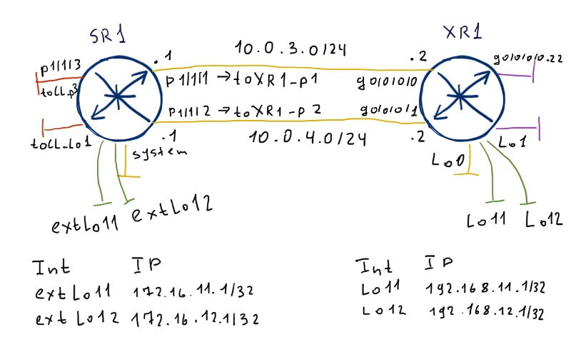
Comparing with the topology before we have two additional loopback interfaces per router. These loopback will be redistributed into OSPF with the following parameters:

To accomplish this task we need to do the following configuration at our routers:

SR1 – Nokia (Alcatel-Lucent) VSR (SR 7750) XR1 – Cisco IOS XRv (ASR 9000)

*A:SR1>config>router>policy-options# info
——————————-
prefix-list “extLo11”
prefix 172.16.11.0/24 through 32
exit
prefix-list “extLo12”
prefix 172.16.12.0/24 through 32
exit
policy-statement “RP_LO_TO_OSPF_1”
entry 10
from
prefix-list “extLo11”
exit
action accept
metric set 11
type 1
exit
exit
entry 20
from
prefix-list “extLo12”
exit
action accept
metric set 12
type 2
exit
exit
default-action reject
exit
——————————-
*A:SR1>config>router>ospf# info
——————————-
asbr
export “RP_LO_TO_OSPF_1”
——————————-

RP/0/0/CPU0:XR1(config)#show conf
prefix-set Lo11
192.168.11.0/24 le 32
end-set
!
prefix-set Lo12
192.168.12.0/24 le 32
end-set
!
route-policy RP_CONN_TO_OSPF_CORE
if destination in Lo11 then
set ospf-metric 11
set metric-type type-1
elseif destination in Lo12 then
set ospf-metric 12
set metric-type type-2
endif
end-policy
!
router ospf CORE
redistribute connected route-policy RP_CONN_TO_OSPF_CORE
!

end

The configuration of loopback isn’t provided as I assume that you can do it without hints already.

Route policies (Policy statement in Nokia (Alcatel-Lucent) SR OS) are very similar between both vendors, so it’s easy to configure both of them even if you know the syntax of only one OS (Nokia(Alcatel-Lucent) SR OR or Cisco IOS XR, it doesn’t matter). Second, the logic of redistribution is also straightforward and similar:

Only routes in routing table (RIB) are redistributed. Routes in other protocols databases aren’t redistributed if they aren’t installed in RIB.

Now I t want to outline some differences in applying of these policies, which confuses me a lot at the beginning (as myself I have strong Cisco background). The first difference is that in Nokia (Alcatel-Lucent) SR OS you have to explicitly enable ASBR (Autonomous System Border Router) functionality by using “asbr” command. In Cisco IOS XR (IOS, IOS XE, NX-OS as well) there is no such command as well as the necessity to somehow mention ASBR-bility of router. At Nokia (Alcatel-Lucent) VSR (SR 7750) you can check, whether it’s applied or not by issuing the following command:

A:SR1# show router ospf 1 status | match Border
Area Border Router   : True
AS Border Router     : True

Cisco IOS XR shows now that peering router also performs ASBR function:

RP/0/0/CPU0:XR1#show ospf CORE border-routers
OSPF CORE Internal Routing Table
Codes: i – Intra-area route, I – Inter-area route
i 10.0.255.1 [100] via 10.0.4.1, GigabitEthernet0/0/0/1, ABR/ASBR , Area 0.0.0.0, SPF 13
i 10.0.255.1 [100] via 10.0.3.1, GigabitEthernet0/0/0/0, ABR/ASBR , Area 0.0.0.0, SPF 13

The information about external routes is distributed via LSA5. Let’s look into their content at our Nokia (Alcatel-Lucent) VSR (SR 7750):

A:SR1# show router ospf 1 database type external detail
============================================================================
OSPFv2 (1) Link State Database (Type : External) (Detailed)
============================================================================
—————————————————————————-
AS Ext LSA for Network 172.16.11.1 (2886732545)
—————————————————————————-
Area Id            : N/A                   Adv Router Id    : 10.0.255.1
Link State Id      : 172.16.11.1 (2886732545)
LSA Type           : AS Ext
Sequence No        : 0x80000001            Checksum         : 0x6410
Age                : 601                   Length           : 36
Options            : E
Network Mask       : 255.255.255.255       Fwding Address   : 0.0.0.0
Metric Type        : Type 1                Metric-0         : 11
Ext Route Tag      : 0x0
—————————————————————————-
AS Ext LSA for Network 172.16.12.1 (2886732801)
—————————————————————————-
Area Id            : N/A                   Adv Router Id    : 10.0.255.1
Link State Id      : 172.16.12.1 (2886732801)
LSA Type           : AS Ext
Sequence No        : 0x80000001            Checksum         : 0xe60b
Age                : 601                   Length           : 36
Options : E
Network Mask       : 255.255.255.255       Fwding Address   : 0.0.0.0
Metric Type        : Type 2                Metric-0         : 12
Ext Route Tag      : 0x0
—————————————————————————-
AS Ext LSA for Network 192.168.11.1 (3232238337)
—————————————————————————-
Area Id            : N/A                   Adv Router Id    : 10.0.255.2
Link State Id      : 192.168.11.1 (3232238337)
LSA Type           : AS Ext
Sequence No        : 0x80000002            Checksum         : 0x6c3b
Age                : 289 Length : 36
Options            : DC
Network Mask       : 255.255.255.255       Fwding Address   : 0.0.0.0
Metric Type        : Type 1                Metric-0         : 11
Ext Route Tag      : 0x0
—————————————————————————-
AS Ext LSA for Network 192.168.12.1 (3232238593)
—————————————————————————-
Area Id            : N/A                   Adv Router Id    : 10.0.255.2
Link State Id      : 192.168.12.1 (3232238593)
LSA Type           : AS Ext
Sequence No        : 0x80000002            Checksum         : 0xee36
Age                : 289                   Length           : 36
Options            : DC
Network Mask       : 255.255.255.255       Fwding Address   : 0.0.0.0
Metric Type        : Type 2                Metric-0         : 12
Ext Route Tag      : 0x0
============================================================================

With the bold text the relevant parameters of OSPF metric-type and metric value are marked, and they fully align with our task, so we are good engineers 🙂

The next consideration is about applying of the route policy itself. In Cisco IOS XR the command structure is “redistribute FROM route-policy WHAT_EXACTLY”, where “FROM” is source of route in routing table and “WHAT_EXACTLY” is actually route-policy that makes both detailed filtering and setting of certain parameters. We can have many such redistribution entries under routing protocol configuration.

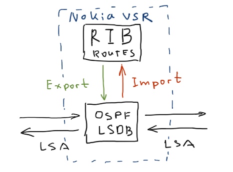
In Nokia (Alcatel-Lucent) SR OS you have only one import/export policy per OSPF configuration. Here are their description:

Think a little bit about it. A couple of times I’ve applied these import/export policies in the wrong direction and therefore completely deleted information in the RIB. The good thing is that it was in lab and no production traffic was affected. Possibly it’s easier to draw this explanation:

Another important consideration about route policies in Nokia (Alcatel-Lucent) SR OS is that you have to configure all type of redistribution in this policy, so take care of its configuration.

Let’s take a look into Cisco IOS XR’s RIB in order to check that now our route policy at SR1 is applied correctly:

RP/0/0/CPU0:XR1#show route ipv4 ospf
O IA 10.0.0.0/8 [254/0] via 0.0.0.0, 00:57:22, Null0
O 10.0.255.1/32 [110/103] via 10.0.4.1, 00:57:22, GigabitEthernet0/0/0/1
.               [110/103] via 10.0.3.1, 00:57:22, GigabitEthernet0/0/0/0
O IA 10.11.0.0/16 [110/100] via 10.0.4.1, 00:57:22, GigabitEthernet0/0/0/1
.                 [110/100] via 10.0.3.1, 00:57:22, GigabitEthernet0/0/0/0
O IA 10.22.0.0/16 [254/0] via 0.0.0.0, 00:57:28, Null0
O E1 172.16.11.1/32 [110/111] via 10.0.4.1, 00:57:22, GigabitEthernet0/0/0/1
.                   [110/111] via 10.0.3.1, 00:57:22, GigabitEthernet0/0/0/0
O E2 172.16.12.1/32 [110/12] via 10.0.4.1, 00:57:22, GigabitEthernet0/0/0/1
.                   [110/12] via 10.0.3.1, 00:57:22, GigabitEthernet0/0/0/0

All routes are here. Now it’s Nokia (Alcatel-Lucent) VSR (SR 7750) turn:

A:SR1# show router route-table protocol ospf
============================================================================
Route Table (Router: Base)
============================================================================
Dest Prefix[Flags]                        Type    Proto    Age       Pref
Next Hop[Interface Name]                                 Metric
—————————————————————————-
10.0.0.0/8                                Blackh* OSPF(1)  00h59m18s 255
Black Hole                                               3
10.0.255.2/32                             Remote  OSPF(1)  00h59m05s 10
10.0.3.2                                                 103
10.0.255.2/32                             Remote  OSPF(1)  00h59m05s 10
10.0.4.2                                                 103
10.11.0.0/16                              Blackh* OSPF(1)  00h59m18s 255
Black Hole                                               0
10.22.0.0/16                              Remote  OSPF(1)  00h59m05s 10
10.0.3.2                                                 200
10.22.0.0/16                              Remote  OSPF(1)  00h59m05s 10
10.0.4.2                                                 200
192.168.11.1/32                           Remote  OSPF(1)  00h59m05s 150
10.0.3.2                                                 111
192.168.11.1/32                           Remote  OSPF(1)  00h59m05s 150
10.0.4.2                                                 111
192.168.12.1/32                           Remote  OSPF(1)  00h59m06s 150
10.0.3.2                                                 12
192.168.12.1/32                           Remote  OSPF(1)  00h59m06s 150
10.0.4.2                                                 12
—————————————————————————-
No. of Routes: 10

Pay attention at Preference of external routes. It’s 150 whereas for internal routes it’s 10. If you compare it to Cisco IOS XR, the latter has the same AD for both types of routes.

This behavior can be changed at Cisco IOS XR with the following command “distance ospf intra-area 110 inter-area 110 external 150” under configuration of OSPF.

Everything looks good and now we can test our connectivity between external routes:

RP/0/0/CPU0:XR1#ping 172.16.11.1 so 192.168.11.1
Wed Jul 18 03:14:15.797 UTC
Type escape sequence to abort.
Sending 5, 100-byte ICMP Echos to 172.16.11.1, timeout is 2 seconds:
!!!!!
Success rate is 100 percent (5/5), round-trip min/avg/max = 1/9/29 ms
RP/0/0/CPU0:XR1#ping 172.16.12.1 so 192.168.12.1
Wed Jul 18 03:14:20.677 UTC
Type escape sequence to abort.
Sending 5, 100-byte ICMP Echos to 172.16.12.1, timeout is 2 seconds:
!!!!!
Success rate is 100 percent (5/5), round-trip min/avg/max = 1/4/9 ms

Cisco IOS XR has one additional option, which allows to summarize external routes in the same way as we have done it for inter area prefixes. In Nokia (Alcatel-Lucent) SR OS unfortunately I have found such option neither in CLI nor in documentation. So I assume that it isn’t implemented, though I can be mistaken. Let’s configure Cisco IOS XR then:

RP/0/0/CPU0:XR1(config)#show conf
router ospf CORE
summary-prefix 192.168.0.0/16
!
end

Now we have only one LSA5 generated by XR1:

A:SR1# show router ospf 1 database type external
============================================================================
OSPFv2 (1) Link State Database (Type : External)
============================================================================
Type     Area Id   Link State Id   Adv Rtr Id Age  Sequence   Cksum
—————————————————————————-
AS Ext   n/a       172.16.11.1     10.0.255.1 464  0x80000003 0x6012
AS Ext   n/a       172.16.12.1     10.0.255.1 464  0x80000003 0xe20d
AS Ext   n/a       192.168.0.0     10.0.255.2 26   0x80000001 0xf1c2
—————————————————————————-
No. of LSAs: 3
============================================================================

In Cisco IOS XR RIB will be installed aggregated route to Null0 just as well as it was done for inter area aggregated route.

Final test of reachability from Nokia (Alcatel-Lucent) VSR (SR 7750):

A:SR1# ping 192.168.11.1 source 172.16.11.1 count 3
PING 192.168.11.1 56 data bytes
64 bytes from 192.168.11.1: icmp_seq=1 ttl=255 time=2.19ms.
64 bytes from 192.168.11.1: icmp_seq=2 ttl=255 time=10.4ms.
64 bytes from 192.168.11.1: icmp_seq=3 ttl=255 time=2.44ms.
—- 192.168.11.1 PING Statistics —-
3 packets transmitted, 3 packets received, 0.00% packet loss
round-trip min = 2.19ms, avg = 5.02ms, max = 10.4ms, stddev = 3.82ms
A:SR1# ping 192.168.12.1 source 172.16.12.1 count 3
PING 192.168.12.1 56 data bytes
64 bytes from 192.168.12.1: icmp_seq=1 ttl=255 time=1.88ms.
64 bytes from 192.168.12.1: icmp_seq=2 ttl=255 time=0.960ms.
64 bytes from 192.168.12.1: icmp_seq=3 ttl=255 time=7.63ms.
—- 192.168.12.1 PING Statistics —-
3 packets transmitted, 3 packets received, 0.00% packet loss
round-trip min = 0.960ms, avg = 3.49ms, max = 7.63ms, stddev = 2.95ms

Fine tuning

In final part we’ll review some additional parameters that makes sense to configure across all you routers in the network. The first such parameter is timers. In order to provide predictable performance, they must be equal at all device in your network. Moreover they default configuration isn’t aggressive enough to provide fast convergence. Let’s compare these parameters:

SR1 – Nokia (Alcatel-Lucent) VSR (SR 7750) XR1 – Cisco IOS XRv (ASR 9000)

A:SR1# show router ospf 1 status | match expression “Delay|Interval”
Init SPF Delay           : 1000 msec
Sec SPF Delay            : 1000 msec
Max SPF Delay            : 10000 msec
Min LS Arrival Interval  : 1000 msec
Init LSA Gen Delay       : 5000 msec
Sec LSA Gen Delay        : 5000 msec
Max LSA Gen Delay        : 5000 msec

RP/0/0/CPU0:XR1#show ospf CORE | utility egrep “[Tt]ime|[Ii]nterval|[Dd]elay”
Initial SPF schedule delay 50 msecs
Minimum hold time between two consecutive SPFs 200 msecs
Maximum wait time between two consecutive SPFs 5000 msecs
Initial LSA throttle delay 50 msecs
Minimum hold time for LSA throttle 200 msecs
Maximum wait time for LSA throttle 5000 msecs
Minimum LSA interval 200 msecs. Minimum LSA arrival 100 msecs

They are really huge, so I want to decrease them:

SR1 – Nokia (Alcatel-Lucent) VSR (SR 7750) XR1 – Cisco IOS XRv (ASR 9000)

*A:SR1>config>router>ospf>timers# info
————————————
spf-wait 1000 10 100
lsa-generate 1000 10 100
lsa-arrival 90
incremental-spf-wait 10
————————————-

RP/0/0/CPU0:XR1(config)#show conf
router ospf CORE
timers throttle lsa all 10 100 100
timers throttle spf 10 100 1000
timers lsa min-arrival 90
!
end

All the parameters are configured in milliseconds, so now we have quite fast network convergence. These timers aren’t the only that we have to configure to speed up the convergence, as it’s in general separate and big topic. Nevertheless these timers are on of its cornerstone.

The next feature is a little bit specific and used usually temporary, though there are some designs, where it’s used permanently. I’m talking about overload (In Cisco it’s called max-metric). Its logic is to configure the maximum metric at all its interfaces therefore exert the router from the traffic forwarding path. Temporary it’s used for maintenance or in router’s boot up. Permanently it’s used at BGP route reflectors in order not to pass data traffic. Let’s assume that I want the router to be out of traffic forwarding for 2 minutes upon boot up:

SR1 – Nokia (Alcatel-Lucent) VSR (SR 7750) XR1 – Cisco IOS XRv (ASR 9000)

A:SR1>config>router>ospf# info
——————————-
overload-on-boot timeout 120
——————————-

RP/0/0/CPU0:XR1(config)#show conf
router ospf CORE
max-metric router-lsa on-startup 120
!
end

There are also some additional features, which I’ll briefly mention. Unfortunately Cisco IOS XRv isn’t fully equivalent of ASR 9000 (at least now) in terms of supported features. The reason for that is architecture of Cisco ASR 9000 series routers. There are a lot of components that are offloaded to linecards CPU and NPU, whereas XRv is a control plane of RSP. BFD is implemented in hardware, that’s why I can’t provide you the configuration of BFD between Nokia (Alcatel-Lucent) VSR (SR 7750) and Cisco IOS XRv

Another useful feature isn’t implemented in Cisco IOS XR at all, though Nokia (Alcatel-Lucent) SR OS supports it. I’m talking about prefix suppression. In general you don’t need to know the IP addresses of interconnect links between routers at the distant routers. So it’s enough just to distribute information about loopbacks, which as typically used as next-hops in BGP / termination points for RSVP-TE tunnels. As Cisco IOS XR can’t do it for OSPF, I won’t show its configuration here.

The third not configurable feature is incremental spf (ispf). In Nokia (Alcatel-Lucent) you can configure its timers, so it seems to be implemented and you can’t deactivate it. In Cisco IOS XR it isn’t implemented at all. At Cisco’s forum I’ve found information, that it isn’t implemented and there is no plans to do it.

Lessons learned

As usually the devil is hidden in the details. The mismatch of default parameters across different vendors very often leads to problems in real environment, if they were not assessed and checked properly in advance. Always check the default configuration and explicitly configure parameters even if you don’t have any doubts.

Conclusion

In this article I tried to cover the most used and useful aspects of configuration of OSPF between Nokia (Alcatel-Lucent) VSR (SR 7750) and Cisco IOS XR (ASR 9000). For sure there are lots of other stuff, which I even haven’t mentioned. Nevertheless you can my configuration and explanation as a basis for your own experiments or production deployment. I hope you enjoy this article. I haven’t provided the configuration of OSPF for IPv6 as it’s fully separate protocol. And it’s the topic for my next article. Take care and good bye!

Final configs: SR1 and XR1

Support us


BR,

Anton Karneliuk

Exit mobile version