Seamless MPLS in Nokia (Alcatel-Lucent) SR OS and Cisco IOS XR
Anton Karneliuk
Hello my friend,
As I’ve promised in the most recent article, I’m going to cover the most scalable and advanced designs for service provider networks. The first such option is Seamless MPLS, so let’s take a look how to deploy it in network built with Nokia (Alcatel-Lucent) SR OS routers and Cisco IOS XR.
Brief overview
Seamless MPLS it isn’t a technology or protocol. It’s rather a framework, which allows you to build really smooth network for all types of services on top of end-to-end MPLS hierarchical LSPs. From the technology/protocols point of view, it’s a mix of RSVP-TE or LDP-based MPLS LSPs + BGP-LU MPLS LSPs + BGP/LDP for services. There are a lot of vendor-specific documentation regarding this framework. For example, Cisco called it Unified MPLS previously, and now it’s called Evolved Programmable Network (EPN). In Nokia (Alcatel-Lucent) it’s called just Seamless MPLS.
I advise you to refer to this RFC draft to get the overall understanding about seamless MPLS.
What are we going to test?
I’m going to build together with you the hierarchical BGP-based MPLS LSP that uses different MPLS transport technologies in different domains (LDP in access and RSVP-TE in core). On top of that we’ll test BGP/MPLS IP VPN. Between PE routers. We aren’t going to test any L2 VPN, because one of the PEs is Cisco IOS XRv, which doesn’t support forwarding plane for such test.
Topology
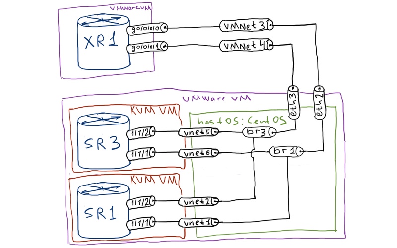
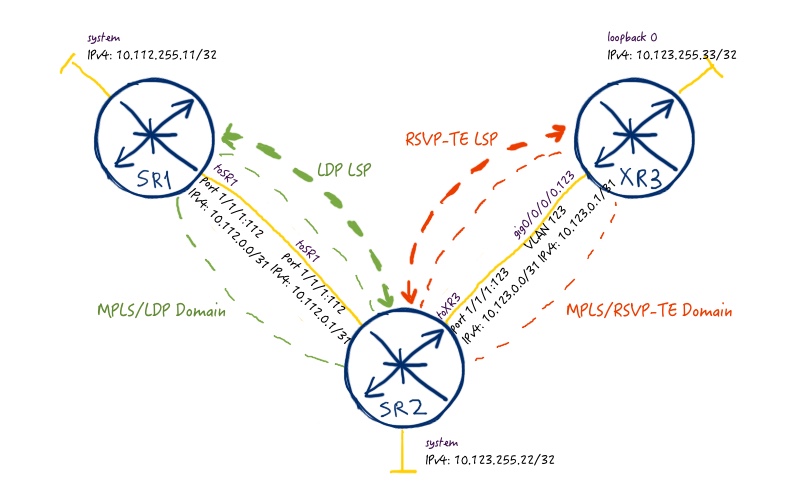
Here is the physical topology, if this is the first my article about Nokia (Alcatel-Lucent) SR OS and Cisco IOS XR you read:
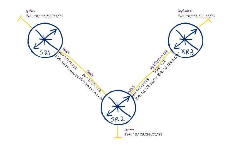
Here is the logical topology:
If you have read my articles previously (link) you might spot that this is probably the easiest logical topology I’ve ever used. That’s true, because we don’t need additional complexity here, as the configuration will be long even without it. In comparison to the previous labs, we don’t have any IGP configured so far. We’ll do it in this lab as we have to configure additional filtering
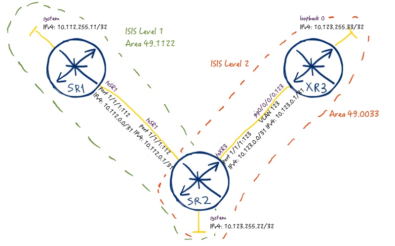
First of all, we need to establish connectivity inside our network. As IGP we’ll use ISIS with two levels:
Level-1 in area 49.1122 is our access network;
Level-2 is core network;
We don’t need any level-1 prefixes to be leaked into level-2, so we’ll configure filtering at SR2 to prevent it. Take a look at the image below to understand routing topology better:
The configuration to achieve this goal looks like the following one:
What we are doing in the configuration above is very straightforward. SR1, which is Nokia (Alcatel-Lucent) VSR residing in access PE, is configured in the area 49.1122 as pure level-1 ISIS router. Router SR2 that we can consider as core PE is configured to act as level-1/2 ISIS node, where level-1 interface goes to SR1 and level-2 interface goes to XR3. SR2 also has route policy, which prevents leaking of level-1 routes into level-2, what is the default operation mode of ISIS. Cisco IOS XR3 is pure level-2 ISIS router, which we consider as service PE (or another core PE). You might spot that all routers are configured with option “advertise passive-only”, what implies that only prefixes of interface put to “passive” state will be advertised.
Let’s check routing tables at our routers. Nokia (Alcatel-Lucent)’s SR1 has the following routes:
A:SR1# show router route-table
============================================================================
Route Table (Router: Base)
============================================================================
Dest Prefix[Flags] Type Proto Age Pref
. Next Hop[Interface Name] Metric
============================================================================
0.0.0.0/0 Remote ISIS 00h18m54s 15
. 10.112.0.1 10
10.112.0.0/31 Local Local 00h38m46s 0
. toSR2 0
10.112.255.11/32 Local Local 00h38m56s 0
. system 0
10.123.255.22/32 Remote ISIS 00h18m54s 15
. 10.112.0.1 10
============================================================================
No. of Routes: 4
============================================================================
You see here two ISIS-learned prefixes: one is address of the system’s interface at SR2 and another is default route generated automatically due to attach (ATT) bit in LSP from SR2. Let’s check SR2 now:
A:SR2# show router route-table
============================================================================
Route Table (Router: Base)
============================================================================
Dest Prefix[Flags] Type Proto Age Pref
. Next Hop[Interface Name] Metric
============================================================================
10.112.0.0/31 Local Local 00h41m17s 0
. toSR1 0
10.112.255.11/32 Remote ISIS 00h22m51s 15
. 10.112.0.0 10
10.123.0.0/31 Local Local 00h41m17s 0
. toXR3 0
10.123.255.22/32 Local Local 00h41m28s 0
. system 0
10.123.255.33/32 Remote ISIS 00h22m51s 18
. 10.123.0.1 10
============================================================================
No. of Routes: 5
============================================================================
At this router we see both system address of SR1 and loopback 0 of XR3. The last but not least is XR3 that is our Cisco IOS XR PE:
RP/0/0/CPU0:XR3#show route ipv4
Codes: C – connected, S – static, R – RIP, B – BGP, (>) – Diversion path
. D – EIGRP, EX – EIGRP external, O – OSPF, IA – OSPF inter area
. N1 – OSPF NSSA external type 1, N2 – OSPF NSSA external type 2
. E1 – OSPF external type 1, E2 – OSPF external type 2, E – EGP
. i – ISIS, L1 – IS-IS level-1, L2 – IS-IS level-2
. ia – IS-IS inter area, su – IS-IS summary null, * – candidate default
. U – per-user static route, o – ODR, L – local, G – DAGR, l – LISP
. A – access/subscriber, a – Application route
. M – mobile route, r – RPL, (!) – FRR Backup path
Gateway of last resort is not set
C 10.123.0.0/31 is directly connected, 05:17:29, GigabitEthernet0/0/0/0.123
L 10.123.0.1/32 is directly connected, 05:17:29, GigabitEthernet0/0/0/0.123
i L2 10.123.255.22/32 [115/10] via 10.123.0.0, 00:29:03, GigabitEthernet0/0/0/0.123
L 10.123.255.33/32 is directly connected, 05:17:29, Loopback0
Each router knows IPv4 address of all system/loopback0 interfaces in its area (for level-1) or level (for level-2). This information is sufficient to build intra-area MPLS tunnels. Let’s do it.
Transport layer 1 / Intra-area MPLS LSP
To make things more interesting, we’ll configure different protocols for MPLS forwarding plane in access and core network. In access network we’ll deploy LDP, whereas in core RSVP-TE will be configured. Refer to the image below:
I don’t tune the default parameters, so configuration for the first level of MPLS forwarding plane is quite simple:
At the first Nokia (Alcatel-Lucent) SR OS router that is SR1 we only activate LDP at interface towards SR2 and activate LDP-IGP Sync. It isn’t necessary in this particular topology, but in general it’s a good practice.
At the second Nokia (Alcatel-Lucent) VSR that is SR2 we configure LDP including LDP-IGP Sync at the interface towards SR1. Another its interface is configured for RSVP-TE operation. MPLS LSP from SR2 to XR3 is really simple as there are no restrictions, only 100 Mbps of bandwidth is reserved.
At the only Cisco IOS XRv router that is XR3 we configure only RSVP-TE at the interface towards SR2 and interface tunnel-te, which is actually RSVP-TE based MPLS LSP. We reserve 100 Mbps of bandwidth for this LSP as well.
There are a couple of commands that are very convenient for checking MPLS forwarding plane. In Nokia (Alcatel-Lucent) SR OS such command is “show router tunnel-table details”, which shows all built MPLS LSPs (actually, GRE tunnels as well) at the router. For SR1 it looks like:
A:SR1# show router tunnel-table detail
============================================================================
Tunnel Table (Router: Base)
============================================================================ Destination : 10.123.255.22/32 NextHop : 10.112.0.1
Tunnel Flags : (Not Specified)
Age : 00h05m09s
CBF Classes : (Not Specified) Owner : ldp Encap : MPLS
Tunnel ID : 65540 Preference : 9 Tunnel Label : 262143 Tunnel Metric : 10 Tunnel MTU : 1496 Max Label Stack : 1
============================================================================
Number of tunnel-table entries : 1
Number of tunnel-table entries with LFA : 0
============================================================================
There is only one MPLS LSP to IPv4 address of SR2’s system interface. As you may guess, at SR2 we have two MPLS LSPs:
A:SR2# show router tunnel-table detail
============================================================================
Tunnel Table (Router: Base)
============================================================================ Destination : 10.112.255.11/32 NextHop : 10.112.0.0
Tunnel Flags : (Not Specified)
Age : 00h12m18s
CBF Classes : (Not Specified) Owner : ldp Encap : MPLS
Tunnel ID : 65537 Preference : 9 Tunnel Label : 262143 Tunnel Metric : 10 Tunnel MTU : 1496 Max Label Stack : 1
============================================================================ Destination : 10.123.255.33/32 NextHop : 10.123.0.1
Tunnel Flags : exclude-for-lfa entropy-label-capable
Age : 00h12m23s
CBF Classes : (Not Specified) Owner : rsvp Encap : MPLS
Tunnel ID : 1 Preference : 7 Tunnel Label : 3 Tunnel Metric : 10 Tunnel MTU : 496 Max Label Stack : 1
LSP ID : 40448 Bypass Label : 0
LSP Bandwidth : 100 LSP Weight : 0
============================================================================
Number of tunnel-table entries : 2
Number of tunnel-table entries with LFA : 0
============================================================================
Preference is used if there are LSPs to the same destination from different owners (i.E. RSVP and LDP). The lower value is more preferable than the higher value. In Cisco IOS XR RSVP is also more preferable than LDP. By the way, let’s check XR3. Usually we use “show mpls forwarding” to check LFIB. But in case of the outgoing RSVP-TE MPLS LSP it doesn’t show anything useful:
RP/0/0/CPU0:XR3#show mpls forwarding
Local Outgoing Prefix Outgoing Next Hop Bytes
Label Label or ID Interface Switched
====== =========== ================== ============ =============== =========
24001 Pop 10.123.255.22/32 tt123 point2point 0
That’s why for our case we need another command:
RP/0/0/CPU0:XR3#show rsvp session detail | include “SESSION|Label|Nam”
SESSION: IPv4-LSP Addr: 10.123.255.22, TunID: 123, ExtID: 10.123.255.33
.Tunnel Name: XR3_to_SR2
. InLabel: No intf, No label
. OutLabel: GigabitEthernet0/0/0/0.123, 262142
. FRR OutLabel: No intf, No label
SESSION: IPv4-LSP Addr: 10.123.255.33, TunID: 1, ExtID: 10.123.255.22
.Tunnel Name: SR2_to_XR3::loose
. InLabel: GigabitEthernet0/0/0/0.123, 3
. OutLabel: No intf, No label
. FRR OutLabel: No intf, No label
Intra-area MPLS LSPs are working now both in access and core network and we can go ahead.
Transport layer 2 / Inter-area hierarchical MPLS LSP
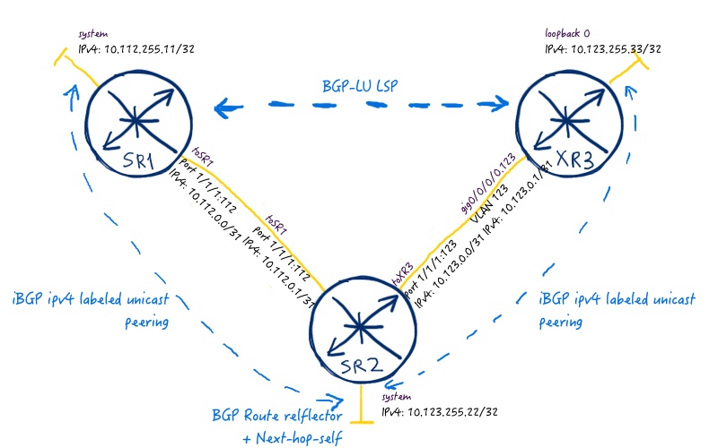
The next step in our journey is to span two separate intra-area MPLS LSPs into one hierarchical inter-area LSP using BGP-LU (BGP labeled unicast). The image below provides more information:
In short words, we configure BGP for IPv4 labeled-unicast address family (AFI/SAFI 1/4). SR2 plays a crucial role here, which is called “inline-RR” (inline route reflector). It not only sends prefixes between iBGP neighbors (BGP route reflector function), but it also puts itself into data path and changes MPLS label (inline).
For more information about BGP and BGP route reflector configuration in Nokia (Alcatel-Lucent) SR OS and Cisco IOS XR refer to the corresponding article.
We need the following configuration to get it working:
Nokia (Alcatel-Lucent) VSR (SR 7750)
Cisco IOS XR (ASR 9000)
SR1
XR3
A:SR1>edit-cfg# candidate view
—————————
configure
router
policy-option
begin
prefix-list PL_IPV4_SYSTEM_INT
prefix 10.112.255.11/32
exit
policy-statement RP_BGP_LU_ANNOUNCE
default-action drop
exit
entry 10
from
protocol direct
prefix-list PL_IPV4_SYSTEM_INT
exit
action accept
exit
exit
entry 20
from
protocol bgp-label
exit
action accept
exit
exit
exit
commit
exit
autonomous-system 65000
bgp
next-hop-resolution
label-route-transport-tunnel
family label-ipv4
resolution any
exit
exit
exit
group iBGP-LU
advertise-inactive
export RP_BGP_LU_ANNOUNCE
family label-ipv4
peer-as 65000
local-address 10.112.255.11
neighbor 10.123.255.22
next-hop-self
exit
exit
exit
exit
exit
—————————
A:SR2>edit-cfg# candidate view
—————————
configure
router
policy-option
begin
prefix-list PL_IPV4_SYSTEM_INT
prefix 10.123.255.22/32
exit
policy-statement RP_BGP_LU_ANNOUNCE
default-action drop
exit
entry 10
from
protocol direct
prefix-list PL_IPV4_SYSTEM_INT
exit
action accept
exit
exit
entry 20
from
protocol bgp-label
exit
action accept
exit
exit
exit
commit
exit
autonomous-system 65000
bgp
next-hop-resolution
label-route-transport-tunnel
family label-ipv4
resolution any
exit
exit
exit
group iBGP-LU
advertise-inactive
export RP_BGP_LU_ANNOUNCE
family label-ipv4
peer-as 65000
cluster 10.123.255.22
local-address 10.123.255.22
neighbor 10.112.255.11
next-hop-self
exit
neighbor 10.123.255.33
next-hop-self
exit
exit
exit
exit
exit
—————————
In Nokia (Alcatel-Lucent) SR OS we have to configure route-policies in order to announce any local prefix. So you can see that we have such routing policy both at SR1 and SR2. Moreover, this route-policy controls all routing information passing by from peer to peer as well, so we have corresponding entry there. In Cisco IOS XR we can also configure redistribution policy or (what is easier) we can just inject network by “network” statement. We need to explicitly configure allocation of labels for IPv4 unciast prefixes in Cisco IOS XR.
BGP-LU address family for IPv4 is called “label-ipv4” in Nokia (Alcatel-Lucent) SR OS and “ipv4 labeled-unicast” in Cisco IOS XR, so we are establishing BGP peering in this address family between our routers. Command “cluster x.x.x.x” at SR2 activates BGP route reflector functionality, and next-hop-self rewrites the original next hop, when the prefix is passing SR2. In Nokia (Alcatel-Lucent) we need to configure “advertise-inactive” function that allows to send BGP prefixes to peers, even if these prefixes aren’t installed in routing table of the router itself (by default it’s deactivated).
In Nokia (Alcatel-Lucent) SR OS we also must configure BGP so that it resolves next hop to built MPLS LSPs. In Cisco IOS XR this process is done automatically via next-hop resolution in routing table.
Let’s check our hierarchical MPLS LSP. We will start at SR1 by reviewing tunnel table:
A:SR1# show router tunnel-table detail
============================================================================
Tunnel Table (Router: Base)
============================================================================
Destination : 10.123.255.22/32
NextHop : 10.112.0.1
Tunnel Flags : (Not Specified)
Age : 00h41m05s
CBF Classes : (Not Specified)
Owner : ldp Encap : MPLS
Tunnel ID : 65537 Preference : 9
Tunnel Label : 262143 Tunnel Metric : 10
Tunnel MTU : 1496 Max Label Stack : 1
============================================================================ Destination : 10.123.255.33/32 NextHop : 10.123.255.22 (65537, ldp)
Tunnel Flags : is-over-tunnel
Age : 00h39m56s
CBF Classes : (Not Specified) Owner : bgp Encap : MPLS
Tunnel ID : 262145 Preference : 12 Tunnel Label : 262138 Tunnel Metric : 1000 Tunnel MTU : 1492 Max Label Stack : 2
============================================================================
Number of tunnel-table entries : 2
Number of tunnel-table entries with LFA : 0
============================================================================
You see that there is two tunnel now, and one of the is BGP-based and has next hop IPv4 address 10.123.255.22, which is available through LDP tunnel. Label and next-hop is known via BGP:
A:SR1# show router bgp routes label-ipv4
============================================================================
BGP Router ID:10.112.255.11 AS:65000 Local AS:65000
============================================================================
Legend –
Status codes : u – used, s – suppressed, h – history, d – decayed, * – valid
. l – leaked, x – stale, > – best, b – backup, p – purge
Origin codes : i – IGP, e – EGP, ? – incomplete
============================================================================
BGP Routes
============================================================================
Flag Network LocalPref MED
. Nexthop (Router) Path-Id Label
. As-Path
============================================================================
i 10.112.255.11/32 100 None
. 10.123.255.22 None 262139
. No As-Path
*i 10.123.255.22/32 100 None
. 10.123.255.22 None 262141
. No As-Path u*>i 10.123.255.33/32 100 0 . 10.123.255.22 None 262138 . No As-Path
============================================================================
Routes : 3
============================================================================
If we check FIB, we’ll see the same information just in the short form:
At SR2 we can check BGP RIB to see, which IPv4 prefixes with labels are being received from both PEs:
A:SR2# show router bgp routes label-ipv4
============================================================================
BGP Router ID:10.123.255.22 AS:65000 Local AS:65000
============================================================================
Legend –
Status codes : u – used, s – suppressed, h – history, d – decayed, * – valid
. l – leaked, x – stale, > – best, b – backup, p – purge
Origin codes : i – IGP, e – EGP, ? – incomplete
============================================================================
BGP Routes
============================================================================
Flag Network LocalPref MED
. Nexthop (Router) Path-Id Label
. As-Path
============================================================================
*i 10.112.255.11/32 100 None
. 10.112.255.11 None 262140
. No As-Path
*i 10.123.255.33/32 100 0
. 10.123.255.33 None 3
. No As-Path
============================================================================
Routes : 2
============================================================================
You see that Cisco IOS XR PE XR3 announces label 3, what means implicit null. You can’t see any “>” sign, because in the routing table there is better routes learned from ISIS.
What about Cisco IOS XR? Good question, let’s check LFIB and BGP RIB:
RP/0/0/CPU0:XR3#show mpls forwarding
Local Outgoing Prefix Outgoing Next Hop Bytes
Label Label or ID Interface Switched
====== =========== ================== ============ =============== =========
24001 Pop 10.123.255.22/32 tt123 point2point 0
24002 262139 10.112.255.11/32 tt123 10.123.255.22 0
!
!
RP/0/0/CPU0:XR3#show bgp ipv4 labeled-unicast
Status codes: s suppressed, d damped, h history, * valid, > best
. i – internal, r RIB-failure, S stale, N Nexthop-discard
Origin codes: i – IGP, e – EGP, ? – incomplete
. Network Next Hop Metric LocPrf Weight Path
*>i10.112.255.11/32 10.123.255.22 100 0 i
*>i10.123.255.22/32 10.123.255.22 100 0 i
*> 10.123.255.33/32 0.0.0.0 0 32768 i
Processed 3 prefixes, 3 paths
!
!
RP/0/0/CPU0:XR3#show bgp ipv4 labeled-unicast labels
Status codes: s suppressed, d damped, h history, * valid, > best
. i – internal, r RIB-failure, S stale, N Nexthop-discard
Origin codes: i – IGP, e – EGP, ? – incomplete
. Network Next Hop Rcvd Label Local Label
*>i10.112.255.11/32 10.123.255.22 262139 24002
*>i10.123.255.22/32 10.123.255.22 262141 24001
*> 10.123.255.33/32 0.0.0.0 nolabel 3
Processed 3 prefixes, 3 paths
We see at all point in the network necessary routing and label information, so we can test our hierarchical MPLS LSP. Just let’s make a ping from SR1 to XR3:
A:SR1# ping 10.123.255.33 source 10.112.255.11 count 1
PING 10.123.255.33 56 data bytes
64 bytes from 10.123.255.33: icmp_seq=1 ttl=255 time=28.5ms.
—- 10.123.255.33 PING Statistics —-
1 packet transmitted, 1 packet received, 0.00% packet loss
round-trip min = 28.5ms, avg = 28.5ms, max = 28.5ms, stddev = 0.000ms
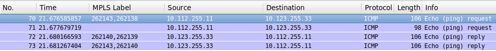
Wireshark show how MPLS labels are being swapped along the path:
We see that both labels are being changed at SR2. If there were more routers between SR1 and SR2 or SR2 and XR2, the second label will be swapped also only at SR2, as it spans two IGP domains into one internetwork. Packet from SR2 to XR3 doesn’t have any labels, because XR3 sginals implicit null label (value “3”) both for RSVP-TE (transport level 1) and BGP (transport level 2) due to PHP operation.
Service layer
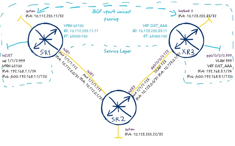
The last step is to test, how services works on top of built hierarchical MPLS LSP. We’ll configure quite easy BGP/MPLS IP VPN to check operation. The service topology is as follows:
The following configuration deploys this service:
Nokia (Alcatel-Lucent) VSR (SR 7750)
Cisco IOS XR (ASR 9000)
SR1
XR3
A:SR1>edit-cfg# candidate view
—————————
configure
router
bgp
next-hop-resolution
label-route-transport-tunnel
family vpn
resolution any
exit
exit
group iBGP_VPNV4
peer-as 65000
local-address 10.112.255.11
family vpn-ipv4 vpn-ipv6
neighbor 10.123.255.33
exit
exit
exit
exit
service
customer 2 create
description CUST_AAA
exit
vprn 65100 customer 2 create
router-id 10.112.255.11
route-distinguisher 10.112.255.11:100
auto-bind-tunnel
resolution any
exit
vrf-target target:65000:100
interface toCUST create
sap 1/1/2:999 create
exit
address 192.168.1.1/24
ipv6
address fc00::192:168:1:1/120
exit
no shutdown
exit
exit
exit
exit
—————————
Just brief overview that we have established BGP peering for vpnv4/vpnv6 unicast address families (AFI/SAFI 1/128 and 2/128) and route tables for IPv4 and IPv6 in corresponding VPRN/VRF. Nokia (Alcatel-Lucent) SR1:
A:SR1# show router bgp summary
=============================================================================
BGP Router ID:10.112.255.11 AS:65000 Local AS:65000
=============================================================================
BGP Summary
=============================================================================
Legend : D – Dynamic Neighbor
=============================================================================
Neighbor
Description
. AS PktRcvd InQ Up/Down State|Rcv/Act/Sent (Addr Family)
. PktSent OutQ
============================================================================
10.123.255.22
. 65000 63 0 00h28m44s 3/1/1 (Lbl-IPv4)
. 61 0
10.123.255.33
. 65000 26 0 00h09m49s 1/1/1 (VpnIPv4)
. 24 0 1/1/1 (VpnIPv6)
============================================================================
!
!
A:SR1# show router 65100 route-table ipv4
============================================================================
Route Table (Service: 65100)
============================================================================
Dest Prefix[Flags] Type Proto Age Pref
. Next Hop[Interface Name] Metric
============================================================================
192.168.1.0/24 Local Local 00h35m05s 0
. toCUST 0
192.168.3.0/24 Remote BGP VPN 00h06m44s 170
. 10.123.255.33 (tunneled:BGP) 0
============================================================================
No. of Routes: 2
============================================================================
!
!
A:SR1# show router 65100 route-table ipv6
============================================================================
IPv6 Route Table (Service: 65100)
============================================================================
Dest Prefix[Flags] Type Proto Age Pref
. Next Hop[Interface Name] Metric
============================================================================
fc00::192:168:1:0/120 Local Local 00h37m43s 0
. toCUST 0
fc00::192:168:3:0/120 Remote BGP VPN 00h09m24s 170
. 10.123.255.33 (tunneled:BGP) 0
============================================================================
No. of Routes: 2
============================================================================
Cisco IOS XR3:
RP/0/0/CPU0:XR3#show bgp vpnv4 uni summary
Neighbor Spk AS MsgRcvd MsgSent TblVer InQ OutQ Up/Down St/PfxRcd
10.112.255.11 0 65000 29 123 7 0 0 00:12:32 1
!
!
RP/0/0/CPU0:XR3#show bgp vpnv6 uni summary
Neighbor Spk AS MsgRcvd MsgSent TblVer InQ OutQ Up/Down St/PfxRcd
10.112.255.11 0 65000 30 123 6 0 0 00:12:35 1
!
!
RP/0/0/CPU0:XR3#show route vrf CUST_AAA ipv4
B 192.168.1.0/24 [200/0] via 10.112.255.11 (nexthop in vrf default), 00:16:58
C 192.168.3.0/24 is directly connected, 00:08:16, GigabitEthernet0/0/0/0.999
L 192.168.3.1/32 is directly connected, 00:08:16, GigabitEthernet0/0/0/0.999
!
!
RP/0/0/CPU0:XR3#show route vrf CUST_AAA ipv6
B fc00::192:168:1:0/120
. [200/0] via ::ffff:10.112.255.11 (nexthop in vrf default), 00:17:31
C fc00::192:168:3:0/120 is directly connected,
. 00:08:49, GigabitEthernet0/0/0/0.999
L fc00::192:168:3:1/128 is directly connected,
. 00:08:49, GigabitEthernet0/0/0/0.999
And finally ping for IPv4:
A:SR1# ping router 65100 192.168.3.1 source 192.168.1.1 count 1
PING 192.168.3.1 56 data bytes
64 bytes from 192.168.3.1: icmp_seq=1 ttl=255 time=5.61ms.
—- 192.168.3.1 PING Statistics —-
1 packet transmitted, 1 packet received, 0.00% packet loss
round-trip min = 5.61ms, avg = 5.61ms, max = 5.61ms, stddev = 0.000ms
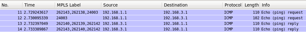
Wireshark trace for it:
Ping for IPv6:
A:SR1# ping 10.123.255.33 source 10.112.255.11 count 1
PING 10.123.255.33 56 data bytes
64 bytes from 10.123.255.33: icmp_seq=1 ttl=255 time=28.5ms.
—- 10.123.255.33 PING Statistics —-
1 packet transmitted, 1 packet received, 0.00% packet loss
round-trip min = 28.5ms, avg = 28.5ms, max = 28.5ms, stddev = 0.000ms
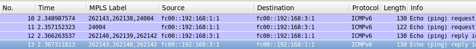
Wireshark trace for it:
You see that the last (bottommost) label is the same across both hops, as it’s signaled and processed only by PEs. The first two labels are transport labels.
During configuration of each lab I face some issues. Sometimes these issues are related to the different operation of the technologies and protocols at different platforms, whereas in the rest of the cases it’s a bugs caused by HW/SW version. But it might be that there is my configuration failure as well 🙂 This time I’ve configured “local-as 65000” instead of “peer-as 65000” at SR1 (Nokia (Alcatel-Lucent) VSR (SR 7750)), what prevents possibility to establish peering with Cisco IOS XR3. “Local-as” feature is used when we want to change our AS in the BGP Hello packets as well as add it to AS_PATH path attribute in BGP update. It’s an optional feature that is not widely used, whereas “peer-as” is mandatory for configuration BGP neighborship. If you don’t configure “peer-as” (in Cisco IOS XR it is called “remote-as”), the BGP peering won’t be established. In logs of Cisco IOS XR there were information, whereas in the log of SR1 I found something like “peer isn’t configured or activated”. Only comparison of the configuration with the working one in a “line-by-line” fashion allowed me to find my own typo. As Brain McGahan from INE said in his CCIE classes: “Troubleshooting is a half of fun”.
Conclusion
In general, seamless MPLS provides you to achieve the highest level of flexibility and scalability inside your network. Using BGP-LU you can different IGP domains, which have their own MPLS transport domains, span into one manageable hierarchical MPLS transport domain. It’s necessary in order to reduce number of routing information (prefixes and labels) at all devices. On low-end devices (like Nokia SAR 7705 or Cisco ASR 901/903) there might be not enough resources to process all prefixes and labels from the whole network, if this network has one level (or one area) flat topology. So seamless MPLS will make it possible for small routers to work. Another advantage is that flapping of interfaces inside one area (changes of link-state information) will be distributed inside small part of the network, speeding up convergence and lowering administrative overhead for links. So, I advise you to use seamless MPLS in your network. Take care and good bye!