MPLS Service to transport mapping in Nokia (Alcatel-Lucent) SR OS and Cisco IOS XR
Anton Karneliuk
Hello my friend,
When we speak about MPLS-based services, we should always remember that they are somehow mapped to the MPLS transport. Depending on vendor (Nokia (Alcatel-Lucent) or Cisco) there are different ways how to achieve it. Let’s discover them!
1 2 3 4 5
No part of this blogpost could be reproduced, stored in a
retrieval system, or transmitted in any form or by any
means, electronic, mechanical or photocopying, recording,
or otherwise, for commercial purposes without the
prior permission of the author.
Brief overview
Mapping of the service to transport LSP means that ingress PE router must define the egress PE and MPLS LSP to it. In basic case the traffic from all services follows the same path (MPLS LSP), but what if you want more? For example, you would like to have traffic engineering tunnels (RSVP-TE MPLS LSP) for certain services in order to guarantee bandwidth or use certain path that won’t be used by default due IGP route calculation, whereas all other services should follow IGP/LDP path.
The approach how vendors achieve differs a lot. In Nokia (Alcatel-Lucent) SR OS you configure SDP (service distribution point), what is exact mapping between service control plane (signaling) and data plane (forwarding – MPLS LSP). Then you mention each necessary SDP under each service configuration. We were already doing this operation upon configuring VPWS or VPLS.
In Cisco IOS XR you don’t do it, because the mapping of service to MPLS LSP is done based on next hop lookup in forwarding database (FIB) and label forwarding database (LFIB). This is the main difference between Nokia (Alcatel-Lucent) SR OS and Cisco IOS XR. In Cisco IOS XR you have only one label in FIB/LFIB for particular destination next-hop, which is ultimately used during traffic forwarding based on next-hop lookup. In Nokia (Alcatel-Lucent) SR OS you will have one MPLS label per MPLS technology (RSVP, LDP, BGP-LU, SPRING) and SDP, which is associated with service, defines MPLS transport to use.
What are we going to test?
We are going to configure 2 different L2 VPN services (LDP and BGP signaled) and also 2 L3 VPN services. Each service will be mapped to its own transport MPLS LSP.
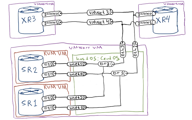
Topology
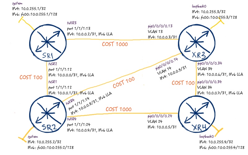
We have 4 routers (2 Nokia (Alcatel-Lucent) SR OS and 2 Cisco IOS XR) that is basis for all my trials:
From architectural point of view for this lab we’ll have two PE routers (SR1 and XR4) and two pure P routers (SR2 and XR3):
IGP for this trial will be OSPF. The cost of interfaces is changed so that default path between SR1 and XR4 (according to SPF) is SR1 – SR2 – XR3 – XR4. Due to this fact all other links aren’t used for pure IP (and default MPLS) forwarding between SR1 and XR4.
Configuration of MPLS data plane (LDP and RSVP-TE) in Nokia (Alcatel-Lucent) SR OS and Cisco IOS XR
First of need to configure MPLS data plane. As I’m going to use different transport protocols (LDP and RSVP-TE), so I have to configure both of them. LDP is RSVP-TE are activated at all interfaces in the network and TE tunnels are built as follows:
SR1 -> SR2 -> XR4 (backup SR1 -> XR3 -> XR4)
SR1 -> XR3 -> XR4 (backup SR1 -> SR2 -> XR4)
XR4 -> SR2 -> SR1 (backup XR4 -> XR3 -> SR1)
XR4 -> XR3 -> SR1 (backup XR4 -> SR2 -> SR1)
The picture below explains this concept in details:
Now we understand, what we need to do, and we come to the next question that is “how to do it”. There is no problem, just configure the network in the following way:
Nokia (Alcatel-Lucent) SR OS
Cisco IOS XR
SR1
XR3
A:SR1>edit-cfg# candidate view
=========================
configure
router
if-attribute
admin-group “RED” value 0
admin-group “GREEN” value 1
exit
mpls
interface “toSR2”
admin-group “GREEN”
exit
interface “toXR3”
admin-group “RED”
exit
no shutdown
exit
rsvp
no shutdown
exit
policy-option
begin
prefix-list “PL_LOOPBACKS”
prefix 10.0.255.0/24 prefix-length-range 32-32
exit
policy-statement “RP_LDP_ANNOUNCE”
entry 10
from
prefix-list “PL_LOOPBACKS”
exit
action accept
exit
exit
default-action drop
exit
exit
commit
exit
exit
ldp
export “RP_LDP_ANNOUNCE”
interface-parameters
interface “toSR2”
exit
interface “toXR3”
exit
exit
exit
ospf
traffic-engineering
exit
mpls
path “loose_1”
no shutdown
exit
path “loose_2”
no shutdown
exit
lsp “SR1_to_XR4_RED”
to 10.0.255.4
cspf
least-fill
primary “loose_1”
include “RED”
bandwidth 141
exit
secondary “loose_2”
standby
include “GREEN”
bandwidth 241
exit
no shutdown
exit
lsp “SR1_to_XR4_GREEN”
to 10.0.255.4
cspf
least-fill
primary “loose_1”
include “GREEN”
bandwidth 241
exit
secondary “loose_2”
standby
include “RED”
bandwidth 131
exit
no shutdown
exit
exit
exit
exit
=========================
RP/0/0/CPU0:XR4(config)#show conf
group OSPF_MPLS
router ospf ‘.*’
mpls ldp auto-config
area ‘.*’
mpls traffic-eng
interface ‘Gig.*’
mpls ldp sync
!
!
mpls traffic-eng router-id Loopback0
!
end-group
interface tunnel-te60401
ipv4 unnumbered Loopback0
signalled-name XR4_to_SR1_over_XR3
autoroute destination 10.0.255.1
destination 10.0.255.1
record-route
path-protection
path-option 10 dynamic attribute-set RED protected-by 20
path-option 20 dynamic attribute-set GREEN
!
interface tunnel-te60411
ipv4 unnumbered Loopback0
signalled-name XR4_to_SR1_over_SR2
autoroute destination 10.0.255.21
destination 10.0.255.1
record-route
path-protection
path-option 10 dynamic attribute-set GREEN protected-by 20
path-option 20 dynamic attribute-set RED
!
router ospf CORE
apply-group OSPF_MPLS
!
rsvp
interface GigabitEthernet0/0/0/0.14
bandwidth 1000000
!
interface GigabitEthernet0/0/0/0.24
bandwidth 1000000
!
interface GigabitEthernet0/0/0/0.34
bandwidth 1000000
!
!
mpls traffic-eng
interface GigabitEthernet0/0/0/0.14
!
interface GigabitEthernet0/0/0/0.24
attribute-names GREEN
!
interface GigabitEthernet0/0/0/0.34
attribute-names RED
!
affinity-map RED bit-position 0
affinity-map GREEN bit-position 1
attribute-set path-option RED
signalled-bandwidth 114000 class-type 0
affinity include RED
!
attribute-set path-option GREEN
signalled-bandwidth 214000 class-type 0
affinity include GREEN
!
!
mpls ldp
router-id 10.0.255.4
!
end
The configuration so far is straightforward:
We enable LDP on all interfaces
We enable RSVP and MPLS-TE at all interfaces and configure corresponding colors to links
We configure TE tunnels (MPLS/RSVP-TE LSP) between SR1 and XR4 with path protection over diverse path
After implementation of the configuration above we have a lot of MPLS LSPs between SR1 and XR4. Let’s take a look at Nokia (Alcatel-Lucent) SR OS router SR1:
Now it’s Cisco IOS XR’s turn. Here we need to take look into different tables, because here is no single table that shows the same information in terms of all outgoing labels/interfaces as in Nokia (Alcatel-Lucent) VSR (SR 7750):
The first table is LFIB and usually you only look into it, but not in case RSVP-TE sessions, when they are originated at this particular router.
In Cisco IOS XR LFIB doesn’t show outgoing labels in case of locally originated RSVP-TE MPLS tunnels.
Field “IPv4-LSP Addr” points to TE router-id of the remote router, that’s why you see here two same session destinations, whereas in routing table different prefixes are mapped two these tunnels:
RP/0/0/CPU0:XR4#show route ipv4 | include tunnel
t 10.0.255.1/32 is directly connected, 00:38:55, tunnel-te60401
t 10.0.255.21/32 is directly connected, 00:38:55, tunnel-te60411
As I’ve said, only at originating Cisco IOS XR router you have such problems with RSVP-TE LSPs. at core router (XR3) you see these transit sessions in LFIB:
After establishment of MPLS transport across all routers in the network we can speak about service mapping.
Mapping of the L2 MPLS VPN service to transport – LDP
As I’ve said in the very beginning, in Cisco world the mapping of the service to the particular LSP is done by mapping it to next-hop (BGP update-source, LDP router-id and so on). So our task is to configure corresponding routing policies at ingress and egress PEs. The following table explains, how we’ll map MPLS L2 services to MPLS LSPs:
Service
PE A
MPLS LSP A -> B
PE B
MPLS LSP B -> A
VPLS_LDP
SR1
LDP
XR4
LDP
VPLS_BGP
SR1
SR1_to_XR4_RED
XR4
tunnel-te60401
As there is different technics, which we should use for BGP and LDP based L2 services, let’s start with LDP:
Nokia (Alcatel-Lucent) SR OS
Cisco IOS XR
SR1
XR4
A:SR1>edit-cfg# candidate view
=========================
configure
port 1/1/2
ethernet
mode access
encap-type dot1q
exit
no shutdown
exit
router
targeted-session
peer 10.0.255.4
local-lsr-id “LO2”
no shutdown
exit
exit
exit
service
customer 2 create
description “LAB_MADNESS”
exit
sdp 11441 mpls create
far-end “10.0.255.4”
signaling tldp
ldp
no shutdown
path-mtu 1518
exit
vpls “1” customer 2 create
def-mesh-vc-id 10001144
mesh-sdp “11441” create
control-word
exit
sap “1/1/2:2001” create
exit
no shutdown
exit
exit
exit
=========================
RP/0/0/CPU0:XR4(config)#show conf
interface GigabitEthernet0/0/0/0.2001 l2transport
encapsulation dot1q 2001
rewrite ingress tag pop 1 symmetric
!
l2vpn
logging
bridge-domain
pseudowire
vfi
!
pw-class AToM
encapsulation mpls
control-word
!
!
bridge group VPLS_SERVICES
bridge-domain VPLS_LDP
interface GigabitEthernet0/0/0/0.2001
!
vfi LDP_CORE_PW
neighbor 10.0.255.11 pw-id 10001144
pw-class AToM
!
!
!
!
!
mpls ldp
address-family ipv4
discovery targeted-hello accept
!
!
end
If you need to refresh the configuration of VPLS services between Nokia (Alcatel-Lucent) SR OS and Cisco IOS XR, refer to the corresponding article.
The only different from VPLS configuration, what we have done previously, is configuration of “local-lsr-id” at Nokia (Alcatel-Lucent) SR OS side. The idea behind is very straightforward: we map this VPLS to LDP-based MPLS LSP, so we need to have at XR4 (Cisco IOS XR) MPLS label delivered by LDP for SR1 (Nokia (Alcatel-Lucent) SR OS). As we have IPv4 prefix 10.0.255.1/32 associated with RSVP-TE tunnel, then another prefix must be used. In Nokia (Alcatel-Lucent) IPv4 address of system interface is used as transport address for all kind of LDP sessions by default, so we need to change this behavior for this case. Having said that we also need to keep in mind that transport address will be changed for all kind of LDP based services between SR1 and XR4. If we have more VPLS instances signaled by LDP, all of them will use the same next-hop (and MPLS LSP) from XR4 to SR1. Some checks at Nokia VSR side:
A:SR1# show router ldp session 10.0.255.4 detail | match expression “Address|StaAdjacency
Type : Targeted State : Established
Local Address : 10.0.255.11 Peer Address : 10.0.255.4
!
!
A:SR1# show service sdp 11441
============================================================================
Service Destination Point (Sdp Id : 11441)
============================================================================
SdpId AdmMTU OprMTU Far End Adm Opr Del LSP Sig
—————————————————————————-
11441 1518 1518 10.0.255.4 Up Up MPLS L TLDP
============================================================================
!
!
A:SR1# show service id 1 base
===============================================================================
Service Basic Information
===============================================================================
Service Id : 1 Vpn Id : 0
Service Type : VPLS
Name : (Not Specified)
Description : (Not Specified)
Customer Id : 2 Creation Origin : manual
Last Status Change: 03/06/2017 13:58:00
Last Mgmt Change : 03/06/2017 13:57:48
Etree Mode : Disabled
Admin State : Up Oper State : Up
MTU : 1514 Def. Mesh VC Id : 10001144
SAP Count : 1 SDP Bind Count : 1
Snd Flush on Fail : Disabled Host Conn Verify : Disabled
SHCV pol IPv4 : None
Propagate MacFlush: Disabled Per Svc Hashing : Disabled
Allow IP Intf Bind: Disabled
Fwd-IPv4-Mcast-To*: Disabled Fwd-IPv6-Mcast-To*: Disabled
Def. Gateway IP : None
Def. Gateway MAC : None
Temp Flood Time : Disabled Temp Flood : Inactive
Temp Flood Chg Cnt: 0
SPI load-balance : Disabled
TEID load-balance : Disabled
Src Tep IP : N/A
VSD Domain : <none>
——————————————————————————-
Service Access & Destination Points
——————————————————————————-
Identifier Type AdmMTU OprMTU Adm Opr
——————————————————————————-
sap:1/1/2:2001 q-tag 1518 1518 Up Up
sdp:11441:10001144 M(10.0.255.4) Mesh 1518 1518 Up Up
===============================================================================
* indicates that the corresponding row element may have been truncated.
Unfortunately, there is no data plane in Cisco IOS XRv, so I can’t simulate the traffic. As indirect evidence of the correct communication, there is constantly increasing counter for MPLS switched traffic to IPv4 prefix 10.0.255.11/32 at XR4.
Mapping of the L2 MPLS VPN service to transport – BGP
Now it’s turn of the BPG service to be mapped to particular MPLS LSP. Just to refresh, what we need to configure:
Service
PE A
MPLS LSP A -> B
PE B
MPLS LSP B -> A
VPLS_LDP
SR1
LDP
XR4
LDP
VPLS_BGP
SR1
SR1_to_XR4_RED
XR4
tunnel-te60401
Let’s see, what we need to configure to launch the second (BGP-based service).
Nokia (Alcatel-Lucent) SR OS
Cisco IOS XR
SR1
XR4
A:SR1>edit-cfg# candidate view
=========================
configure
port 1/1/2
ethernet
mode access
encap-type dot1q
exit
no shutdown
exit
router
autonomous-system 65000
bgp
next-hop-resolution
label-route-transport-tunnel
family vpn
resolution any
exit
exit
exit
group “iBGP_PEER”
peer-as 65000
family l2-vpn
local-address “10.0.255.1”
neighbor “10.0.255.4”
exit
exit
exit
exit
service
sdp-group
group-name “BGP_L2_SERVICE” value 1
exit
sdp 11442 mpls create
far-end “10.0.255.4”
lsp “SR1_to_XR4_RED”
signaling bgp
sdp-group “BGP_L2_SERVICE”
path-mtu 1518
no shutdown
exit
pw-template 1 use-provisioned-sdp create
sdp-include “BGP_L2_SERVICE”
exit
vpls “2” customer 2 vpn 10004411 create
bgp
pw-template-binding 1
exit
route-distinguisher “10.0.255.1:2002”
route-target “target:65000:2002”
exit
bgp-vpls
max-ve-id 1000
ve-name “SR1”
ve-id 11
exit
no shutdown
exit
sap “1/1/2:2002” create
exit
no shutdown
exit
exit
exit
=========================
At Cisco IOS XR router XR4 the traffic for this VPLS service must be mapped to TE tunnel 60401, which means that default BGP next-hop of SR1, which is IPv4 address 10.0.255.1, is used. So no modification with outgoing (or export) BGP policy is needed. At Nokia (Alcatel-Lucent) SR OS side we just map VPLS to certain MPLS LSP using spd-group and pw-template.
Some checks at SR1 side:
A:SR1# show router bgp routes l2-vpn
===============================================================================
BGP Router ID:10.0.255.1 AS:65000 Local AS:65000
===============================================================================
Legend –
Status codes : u – used, s – suppressed, h – history, d – decayed, * – valid
l – leaked, x – stale, > – best, b – backup, p – purge
Origin codes : i – IGP, e – EGP, ? – incomplete
===============================================================================
BGP L2VPN Routes
===============================================================================
Flag RouteType Prefix MED
RD SiteId Label
Nexthop VeId BlockSize LocalPref
As-Path BaseOffset vplsLabelBa
se
——————————————————————————-
u*>i VPLS – – None
10.0.255.4:2002 – –
10.0.255.4 44 10 100
No As-Path 11 24030
u*>i VPLS – – None
10.0.255.4:2002 – –
10.0.255.4 44 10 100
No As-Path 41 24015
——————————————————————————-
Routes : 2
===============================================================================
!
!
A:SR1# show service id 2 base
===============================================================================
Service Basic Information
===============================================================================
Service Id : 2 Vpn Id : 10004411
Service Type : VPLS
Name : (Not Specified)
Description : (Not Specified)
Customer Id : 2 Creation Origin : manual
Last Status Change: 03/06/2017 16:18:20
Last Mgmt Change : 03/06/2017 16:45:59
Etree Mode : Disabled
Admin State : Up Oper State : Up
MTU : 1514 Def. Mesh VC Id : 2
SAP Count : 1 SDP Bind Count : 1
Snd Flush on Fail : Disabled Host Conn Verify : Disabled
SHCV pol IPv4 : None
Propagate MacFlush: Disabled Per Svc Hashing : Disabled
Allow IP Intf Bind: Disabled
Fwd-IPv4-Mcast-To*: Disabled Fwd-IPv6-Mcast-To*: Disabled
Def. Gateway IP : None
Def. Gateway MAC : None
Temp Flood Time : Disabled Temp Flood : Inactive
Temp Flood Chg Cnt: 0
SPI load-balance : Disabled
TEID load-balance : Disabled
Src Tep IP : N/A
VSD Domain : <none>
——————————————————————————-
Service Access & Destination Points
——————————————————————————-
Identifier Type AdmMTU OprMTU Adm Opr
——————————————————————————-
sap:1/1/2:2002 q-tag 1518 1518 Up Up
sdp:11442:4294967291 S(10.0.255.4) BgpVpls 1518 1518 Up Up
===============================================================================
* indicates that the corresponding row element may have been truncated.
… And at XR4 side:
RP/0/0/CPU0:XR4#show bgp l2vpn vpls
Status codes: s suppressed, d damped, h history, * valid, > best
i – internal, r RIB-failure, S stale, N Nexthop-discard
Origin codes: i – IGP, e – EGP, ? – incomplete
Network Next Hop Rcvd Label Local Label
Route Distinguisher: 10.0.255.1:2002
*>i11:9/32 10.0.255.1 262134 nolabel
*>i11:41/32 10.0.255.1 262111 nolabel
Route Distinguisher: 10.0.255.4:2002 (default for vrf VPLS_SERVICES:VPLS_BGP)
*>i11:9/32 10.0.255.1 262134 nolabel
*>i11:41/32 10.0.255.1 262111 nolabel
*> 44:11/32 0.0.0.0 nolabel 24030
*> 44:41/32 0.0.0.0 nolabel 24015
Again we can’t test data plane.
Mapping of the L3 MPLS VPN service to transport
Finally, we have reached the L3 services. Here is the only signalling option possible, so we’ll configure both VPNs simultaneously. I’m gonna to make the following mapping across MPLS LSPs:
Service
PE A
MPLS LSP A -> B
PE B
MPLS LSP B -> A
L3VPN_A
SR1
LDP
XR4
LDP
L3VPN_B
SR1
SR1_to_XR4_GREEN
XR4
Tunnel-te60411
Let’s convert this table into language, which Nokia (Alcatel-Lucent) SR OS and Cisco IOS XR understands:
Nokia (Alcatel-Lucent) SR OS
Cisco IOS XR
SR1
XR4
A:SR1>edit-cfg# candidate view
=========================
configure
router
policy-option
begin
community “CL_L3VPN_A” members “target:65000:2003”
community “CL_L3VPN_B” members “target:65000:2004”
policy-statement “RP_L3VPN_A_EX”
default-action accept
community add “CL_L3VPN_A”
next-hop 10.0.255.11
exit
exit
policy-statement “RP_L3VPN_B_EX”
default-action accept
community add “CL_L3VPN_B”
next-hop 10.0.255.21
exit
exit
commit
exit
exit
service
vprn 2003 customer 2 create
vrf-export “RP_L3VPN_A_EX”
route-distinguisher 10.0.255.1:2003
auto-bind-tunnel
resolution any
exit
vrf-target target:65000:2003
interface “Lo2003” create
address 192.168.3.1/32
ipv6
address fc00::192:168:3:1/128
exit
loopback
exit
no shutdown
exit
sdp 11443 mpls create
far-end 10.0.255.4
lsp “SR1_to_XR4_GREEN”
keep-alive
shutdown
exit
no shutdown
exit
vprn 2004 customer 2 create
vrf-export “RP_L3VPN_B_EX”
route-distinguisher 10.0.255.1:2004
vrf-target target:65000:2004
interface “Lo2004” create
address 192.168.4.1/32
ipv6
address fc00::192:168:4:1/128
exit
loopback
exit
spoke-sdp 11443 create
exit
no shutdown
exit
exit
exit
=========================
If you need to refresh some knowledge about BGP/MPLS IP VPN configuration and verification in Nokia (Alcatel-Lucent) SR OS and Cisco IOS XR, read this article.
There are two unusual things in VPRF/VRF configuration caused by our task:
For vprn 2004 in Nokia (Alcatel-Lucent) SR OS I statically define spoke SDP in order to map it to certain MPLS LSP. Also we have vrf-export policies configured per VRF that defines next-hop, so that XR4 can map it to corresponding MPLS LSP
In Cisco IOS XR we define route-policy for vpnv4/vpnv6 address families that changes next hop based on the route target (extended community), so SR1 maps it corresponding VPRN.
After all the BGP sessions are established, you will see VPN prefixes at both PEs with corresponding next-hops and its mapping to transport MPLS LSPs. The first thing to review is BGP RIM at Nokia (Alcatel-Lucent) SR OS router SR1:
A:SR1# show router bgp routes vpn-ipv4
===============================================================================
BGP Router ID:10.0.255.1 AS:65000 Local AS:65000
===============================================================================
Legend –
Status codes : u – used, s – suppressed, h – history, d – decayed, * – valid
l – leaked, x – stale, > – best, b – backup, p – purge
Origin codes : i – IGP, e – EGP, ? – incomplete
===============================================================================
BGP VPN-IPv4 Routes
===============================================================================
Flag Network LocalPref MED
Nexthop (Router) Path-Id Label
As-Path
——————————————————————————-
u*>? 10.0.255.4:2003:192.168.3.4/32 100 0 10.0.255.14 None 24011
No As-Path
u*>? 10.0.255.4:2004:192.168.4.4/32 100 0 10.0.255.4 None 24012
No As-Path
——————————————————————————-
Routes : 2
===============================================================================
You see here two next-hops and corresponding labels. Then if you check per-VPRN FIB, you will see how these prefixes are mapped to transport LSPs:
We have all the necessary information at SR1 to forward the traffic from SR1 to XR4. For the sake of comletness, let’s check the same (or similar) tables at Cisco IOS XR router XR4:
RP/0/0/CPU0:XR4#show bgp vpnv4 unicast labels
Status codes: s suppressed, d damped, h history, * valid, > best
i – internal, r RIB-failure, S stale, N Nexthop-discard
Origin codes: i – IGP, e – EGP, ? – incomplete
Network Next Hop Rcvd Label Local Label
Route Distinguisher: 10.0.255.1:2003
*>i192.168.3.1/32 10.0.255.11 262133 nolabel
Route Distinguisher: 10.0.255.1:2004
*>i192.168.4.1/32 10.0.255.21 262132 nolabel
Route Distinguisher: 10.0.255.4:2003 (default for vrf L3VPN_A)
*>i192.168.3.1/32 10.0.255.11 262133 nolabel
*> 192.168.3.4/32 0.0.0.0 nolabel 24011
Route Distinguisher: 10.0.255.4:2004 (default for vrf L3VPN_B)
*>i192.168.4.1/32 10.0.255.21 262132 nolabel
*> 192.168.4.4/32 0.0.0.0 nolabel 24012
Processed 6 prefixes, 6 paths
!
!
RP/0/0/CPU0:XR4#show mpls forwarding
Local Outgoing Prefix Outgoing Next Hop Bytes
Label Label or ID Interface Switched
—— ———– —————— ———— ————— ————
24000 Pop 10.0.255.1/32 tt60401 point2point 0
24001 262143 10.0.255.2/32 Gi0/0/0/0.24 10.0.0.4 12138
24002 262139 10.0.255.11/32 Gi0/0/0/0.24 10.0.0.4 31099
24003 262141 10.0.255.12/32 Gi0/0/0/0.24 10.0.0.4 0
24004 Pop 10.0.255.21/32 tt60411 point2point 0
24005 Unlabelled 10.0.0.0/31 Gi0/0/0/0.24 10.0.0.4 0
24006 Unlabelled 10.0.0.2/31 Gi0/0/0/0.24 10.0.0.4 0
24007 Unlabelled 10.0.0.8/31 Gi0/0/0/0.24 10.0.0.4 0
24010 Pop PW(10.0.255.11:10001144) \
BD=1 point2point 0
24011 Aggregate L3VPN_A: Per-VRF Aggr[V] \
L3VPN_A 2960
24012 Aggregate L3VPN_B: Per-VRF Aggr[V] \
L3VPN_B 2260
24013 Aggregate L3VPN_A: Per-VRF Aggr[V] \
L3VPN_A 0
24014 Aggregate L3VPN_B: Per-VRF Aggr[V] \
L3VPN_B 0
24030 Pop PW(10.0.255.1:10004411) \
BD=0 point2point 0
!
!
RP/0/0/CPU0:XR4#show rsvp session detail | include “Label|SESSION”
SESSION: IPv4-LSP Addr: 10.0.255.1, TunID: 60401, ExtID: 10.0.255.4
InLabel: No intf, No label
OutLabel: GigabitEthernet0/0/0/0.24, 262136
FRR OutLabel: No intf, No label
SESSION: IPv4-LSP Addr: 10.0.255.1, TunID: 60411, ExtID: 10.0.255.4
InLabel: No intf, No label
OutLabel: GigabitEthernet0/0/0/0.24, 262135
FRR OutLabel: No intf, No label
We know now how the label stacks at both PEs SR1 and XR4 should look like and we can do some tests with packet forwarding:
RP/0/0/CPU0:XR4#show route vrf L3VPN_A
B 192.168.3.1/32 [200/0] via 10.0.255.11 (nexthop in vrf default), 00:02:16
L 192.168.3.4/32 is directly connected, 00:13:31, Loopback2003
!
!
RP/0/0/CPU0:XR4#ping vrf L3VPN_A 192.168.3.1 source 192.168.3.4
Type escape sequence to abort.
Sending 5, 100-byte ICMP Echos to 192.168.3.1, timeout is 2 seconds:
!!!!!
Success rate is 100 percent (5/5), round-trip min/avg/max = 9/19/39 ms
Wireshark shows us the following picture, which fully corresponds provided output:
And another test:
RP/0/0/CPU0:XR4#show route vrf L3VPN_B
B 192.168.4.1/32 [200/0] via 10.0.255.21 (nexthop in vrf default), 00:02:31
L 192.168.4.4/32 is directly connected, 00:13:46, Loopback2004
!
!
RP/0/0/CPU0:XR4#ping vrf L3VPN_B 192.168.4.1 source 192.168.4.4
Type escape sequence to abort.
Sending 5, 100-byte ICMP Echos to 192.168.4.1, timeout is 2 seconds:
!!!!!
Success rate is 100 percent (5/5), round-trip min/avg/max = 1/9/19 ms
And trace from Wireshark:
The key take away is that there are different transport labels for these two traffic flows, what means that they are really mapped to different transport MPLS LSPs.
The final configuration files are here:
Lessons learned
In the beginning I’ve configured TE-tunnels at Cisco IOS XRv (ASR 9000) as follows:
RP/0/0/CPU0:XR4#show run interface tunnel-te60401
interface tunnel-te60401
ipv4 unnumbered Loopback0
signalled-name XR4_to_SR1_over_XR3 autoroute destination 10.0.255.1
destination 10.0.255.1
record-route
path-protection
path-option 10 dynamic attribute-set RED protected-by 20
path-option 20 dynamic attribute-set GREEN
!
end
The command marked with bold installs route to this prefix (10.0.255.21/32) into routing table. Though I was able to make MPLS traceroute and ping remote end (SR1) through this tunnel, mapped services was not working. I.E. I saw the following indication at XR4:
RP/0/0/CPU0:XR4#show l2vpn bridge-domain bd-name VPLS_BGP detail | include “neighbor 10.0.255.1”
PW: neighbor 10.0.255.1, PW ID 10004411, state is down ( provisioned ) (Transport LSP Down)
I haven’t found in internet solution for this message and make another configuration. Previously in “ordinary” Cisco IOS there was no such “autoroute destination” command and mainly the mapping of prefix to the tunnel was done using static routes:
RP/0/0/CPU0:XR4(config)#show conf
interface tunnel-te60401
no autoroute destination 10.0.255. 1
!
interface tunnel-te60411
no autoroute destination 10.0.255.21
!
router static
address-family ipv4 unicast
10.0.255.1/32 tunnel-te60401
10.0.255.21/32 tunnel-te60411
!
!
end
After applying it I become the following message in syslog:
RP/0/0/CPU0:Mar 8 08:13:00.419 : l2vpn_mgr[1182]: %L2-L2VPN_PW-3-UPDOWN : Pseudowire with address 10.0.255.1, id 10004411, state is changed to: Up
And check of the configuration shows pretty nice working neighbor in VPLS:
RP/0/0/CPU0:XR4#show l2vpn bridge-domain bd-name VPLS_BGP detail | include “neighbor 10.0.255.1”
PW: neighbor 10.0.255.1, PW ID 10004411, state is up ( established )
Old good static routes!
Conclusion
Manipulation of next-hop for services (like BGP next-hop addresses or session’s IP addresses for LDP) adds another level of scalability and flexibility to deploy your networks. This toolset is particular important for traffic engineering scenarios, when you want to achieve better network resources utilization or assure certain parameters for certain services. Take care and good bye!