Hello my friend,
We have already reviewed the configuration of VPWS for a classical case, when we need to provide L2 transport over IP/MPLS network. But this is not the single application that uses VPWS. Another useful and widely used example is L3 termination of the clients, connected at L2 to access IP/MPLS network.
1 2 3 4 5 | No part of this blogpost could be reproduced, stored in a retrieval system, or transmitted in any form or by any means, electronic, mechanical or photocopying, recording, or otherwise, for commercial purposes without the prior permission of the author. |
Brief overview
There are numerous reasons, why you don’t terminate the clients directly at access node (AN). For example, low end routers can’t terminate such connections in IP VPN instance (VPRN for Nokia (Alcatel-Lucent) and VRF for Cisco) or termination of user services at BNG, which is connected via IP/MPLS in access network. The latter case can be also implemented via L2TP, if you network is pure routed without MPLS, but in case of IP/MPLS network usage of PWHE is much more recommended.
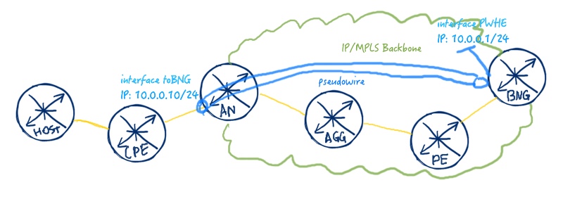
The idea of PWHE service is shown at the image below:

The client devices (CPE) is connected via normal Ethernet connection to AN, which starts VPWS service in the direction of BNG. BNG terminates this VPWS from AN and L2 segment from CPE, as BNG has IPv4/IPv6 address at L3 interface that terminates this pseudowire.
What are we going to test?
We are going to configure 2 PWHE services:
- CPE (Cisco) – AN (Nokia (Alcatel-Lucent)) – BNG (Cisco)
- CPE (Nokia (Alcatel-Lucent)) – AN (Cisco) – BNG (Nokia (Alcatel-Lucent))
The image of the service will be provided later in the configuration section
Topology
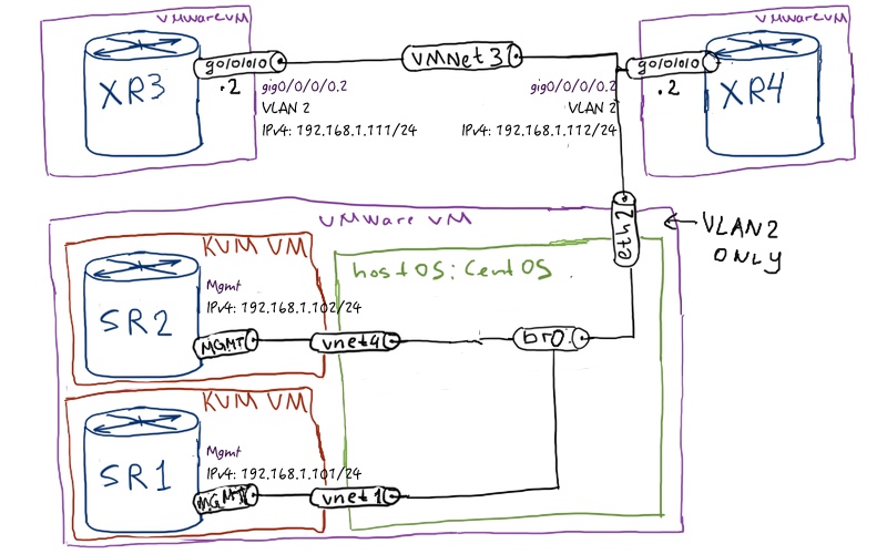
Physical topology has 4 routers: two Nokia (Alcatel-Lucent) VSR (SR 7750) and two Cisco IOS XRv (ASR 9000) routers. Those of you, who have read my articles previously, this topology is familiar:

If you want to know, how to build such lab setup, I advise to jump to the very beginning.
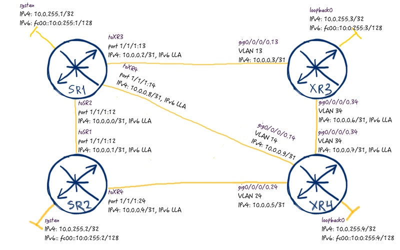
Logical topology was also previously configured:

Initial configuration files, which you can use in order to align my setup, are here:
config_initial_linux config_initial_sr1 config_initial_sr2 config_initial_xr3 config_initial_xr4
Case 1 – Nokia (Alcatel-Lucent) as PWHE/BNG, Cisco as AN
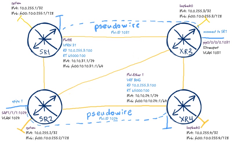
We’ll configure two independent PWHE services with two independent VPWS to show the difference and configuration in Nokia (Alcatel-Lucent) SR OS and Cisco IOS XR. The following image, as I’ve promised previously, will explain how to do it:

In order to show and explain some differences, we’ll configure these cases separately. The first one is Nokia (Alcatel-Lucent) SR OS acting as PWHE and Cisco IOS XR is AN:
| Nokia (Alcatel-Lucent) SR OS | Cisco IOS XR |
| SR1 | XR3 |
|
A:SR1>edit-cfg# candidate view |
RP/0/0/CPU0:XR3(config)#show conf |
More information about VPLS configuration and verification you will find in the dedicated article.
Here you can see two different options, how you can configure PWHE that depends on vendor. In case of Nokia (Alcatel-Lucent) SR OS is PWHE you configure pseudowire in ethernet mode without control-word, because it is not allowed to configure it in such a way (SR1 configuration). Also you terminate VPWS directly at L3 interface, which terminates this segment (it’s possible to attach more than one spoke-sdp). Then at Cisco IOS XR you need to configure pseudowire in the same way in order to bring it to life. Also you need to adapt MTU, because Nokia (Alcatel-Lucent) SR OS and Cisco IOS XR treat MTU in different manner.
More information on MTU you can find in the separate article.
We need to assure that VPWS is established and that L3 interface at BNG router is up and running in proper VPRN.
|
A:SR1# show service id 31 base |
If you have problems with VPWS establishment it’s also useful to check parameters those must be negotiated in LDP session:
|
A:SR1# show router ldp bindings services detail |
At Cisco IOS XR side the only thing that must be checked is VPWS configuration:
|
RP/0/0/CPU0:XR3#show l2vpn xconnect detail |
Unfortunatelly Cisco IOS XRv doesn’t support forwarding plane for L2 VPNs so we can’t make simulations. But as control plane is up and running, we can consider that our PWHE at Nokia (Alcatel-Lucent) SR OS router is working as proper.
Case 2 – Nokia (Alcatel-Lucent) as AN, Cisco as PWHE/BNG
Let’s briefly recap the topology:

Now we configure pseudowire termination (PWHE) at Cisco IOS XR and Nokia (Alcatel-Lucent) SR OS plays role of AN:
| Nokia (Alcatel-Lucent) SR OS | Cisco IOS XR |
| SR2 | XR4 |
|
A:SR2>edit-cfg# candidate view |
RP/0/0/CPU0:XR4(config)#show conf |
In case of Cisco IOS XR is configured as PWHE, you have two options. One option is the same as it was previously with Nokia (Alcatel-Lucent) SR OS, so you configure pseudowire in Ethernet mode (this time you can configure it with control-word as Cisco IOS XR allows it in PWHE). Then all the traffic will be mapped to a single PW-Ether interface.
Another option, which is actually configure in my example, is configuring pseudowire in VLAN mode, so that VLAN tag is preserved across the transmission in VPWS. When Cisco IOS XR become the traffic at this particular pseudowire, it puts the traffic to associated PW-Ether interface. If this interface has sub-interface in the corresponding VLAN, traffic is destined there. This allows you easily map traffic of the customers in particular VRFs.
One difference in Cisco IOS XR from Nokia (Alcatel-Lucent) SR OS is that you define interface list, which defines interfaces those are allowed to receive PWHE traffic.
Here the checks are quite opposite and we’ll start at Cisco IOS XR router XR4, what is PWHE in our lab:
|
RP/0/0/CPU0:XR4#show l2vpn xconnect detail |
At Nokia (Alcatel-Lucent) SR OS side we just need to check the status of our VPWS (epipe) service:
|
A:SR2# show service id 1 base |
That’s it. As in the previous lab, we unfortunately can’t perform simulation as Cisco IOS XRv doesn’t support data plane for L2 VPNs.
Final configuration files are the following: config_final_sr2 config_final_xr3 config_final_xr4 config_final_sr1
Lessons learned
If something works in one direction it doesn’t mean that it works in the reverse direction in the same way. This is fully applicably for our case, where Nokia (Alcatel-Lucent) SR OS and Cisco IOS XR can have different pseudowire types depending on who is BNG and who is AN. Knowing (or testing of these nuances) helps you to define the most efficient solution.
Conclusion
PWHE is one of the most useful solution today, if your access network is IP/MPLS. You can compare it to VPDN/L2TP as user termination technology in case of purely routed IP network. The goal is just the same: backhaul the customer traffic to the BNG. And here VPWS plays very helpful role for you by providing this backhauling. Use MPLS. Take care and good bye!
Support us
BR,
Anton Karneliuk


Hi Anton,
Does PWHE support any type of redundancy? what if one BNG fails and you need to terminate subscriber to different BNG?
thank
Hi Tim,
The topic redundancy is very interesting and there are numerous option how you can achieve the result. Basicaly VPWS has built in mechanism for redunandcy via configuration of backup peer inside PW. Another option would be configuration of several BNGs with the same IP address fo customer termination and usage of HA/clustering or anycast IP.
BR,
Anton