Hello my friend,
Having covered IPv4/OSPFv2 in the previous article I was constantly thinking about improving topology as it’s difficult to show many interesting things having only two routers. And finally I find the way how to do it. In this article about IPv6/OSPFv3 the topology is two times bigger and now we have 4 virtual routers. Let’s discover how IPv6 traffic is routed by OSPFv3.
Disclaimer
A lot of theory regarding interface types, MTU mismatch and so on was covered in the article about IPv4/OPSFv2. I strongly recommend reading it before reading this article, as here I won’t explain them again.
Lab tuning
As I’ve already said in the very beginning, I wanted to add devices into my lab to provide better explanation of routing concepts. First my step was to remove all unnecessary application that uses my memory. That allowed me to launch one more instance of Nokia (Alcatel-Lucent) VSR. Memory usage at my laptop currently looks like:
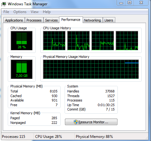
Three devices are far better than only two, as I can configure different areas and show inter-area routes propagation. But as ABR I have to use either Cisco IOS XRv or Nokia (Alcatel-Lucent) VSR, so not both vendors are covered equally then. The next step that I’ve taken is virtualization of virtual Cisco IOS XRv router by configuring additional VRF (virtual routing and forwarding instance), which for this lab works perfectly as a separate router. It isn’t possible to use such trick for all the topologies and technologies, but here it gives me the possibility to build bigger OSPF domain. Actually I can run much more VRFs (it’s virtually unlimited number), but one additional is enough. Though configuration of VRF at Cisco IOS XR is very straightforward, I won’t explain it in this article for two reasons. First, it’s a topic for separate article, and second, the configuration of OSPFv3 in VRF is just the same as without. So for current article we consider VRF as fully functional additional router.
Such approach Cisco calls VRF-lite
Topology
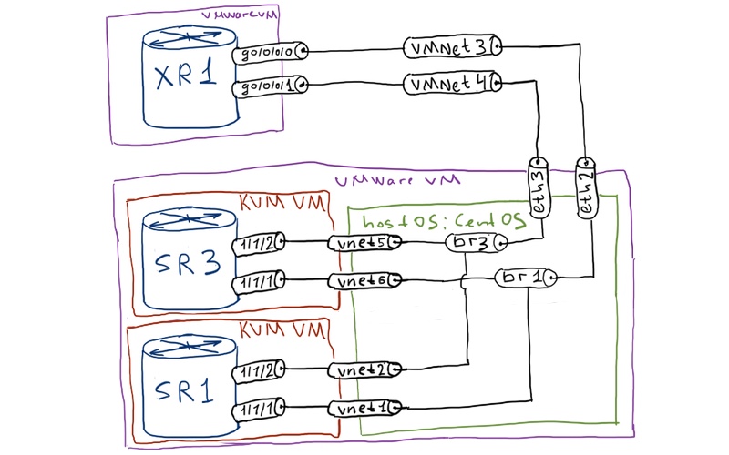
Physical topology is almost the same as it was in the article about OSPFv2 besides the fact that now we have one additional KVM VM, which is attached to two internal bridges in Linux host:
Logical topology is a little bit complicated comparing to the OSPFv2 as I have more routers in the topology and therefore I have to configure trunking to satisfy my requirements:
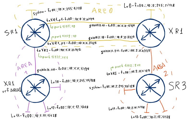
If you have questions how to configure trunk in Nokia (Alcatel-Lucent) SR OS, Cisco IOS XR or Linux, read this article.
As you can see we have only IPv6 addresses here. Based on the findings from my article about trunking, I have to modify bridging in Linux by mapping each trunk to separate bridge. I won’t explain it, so you can dig into details yourself. Having read article about trunking it’s easy. Also I have explicitly configured IPv6 link-local addresses both at Nokia (Alcatel-Lucent) VSR (SR 7750) and Cisco IOS XR (ASR 9000). The initial configuration files you can find here: SR3_initial XR1+AREA1_final SR1_initial
Basic OSPFv3 connectivity
In general I’ll follow the same logic as it was with OSPFv2 moving from easy to more advanced topics. Nevertheless here we’ll configure multi-area topology from the beginning. Interface (or network) types will be the following:
| Media type | SR1 | SR3 | XR1 | XR1 (vrf AREA1) |
| Point-to-point | toXR1_p1 | toXR1 | Gig0/0/0/1.211 Gig0/0/0/0.10 |
|
| Broadcast | toXR1_p2 toXR2 |
– | Gig0/0/0/1.10 | Gig0/0/0/0.111 |
Types of all areas at the beginning will be default. We will change some of them later to see the differences. The mapping of interfaces to the areas will be the following:
| Area | Prefix |
| 0.0.0.0 | fc00::10:0:x:x/96 |
| 0.0.0.1 | fc00::10:1:x:x/96 |
| 0.0.0.2 | fc00::10:2:x:x/96 |
Basic guidelines are established, so now it’s CONFIG time! Pay also attention how OSPFv3 process defined in Nokia (Alcatel-Lucent) SR OS. In OSPFv2 I have configured it with distinct process-id though here I don’t mention it. In general you can omit process-id if you have only one topology or if you configure core network (not CE-facing process):
| Nokia (Alcatel-Lucent) VSR (SR 7750) | Cisco IOS XR (ASR 9000) |
| SR1 | XR1 |
|
*A:SR1>config>router>ospf3$ info |
RP/0/0/CPU0:XR1(config)#show conf |
| SR3 | XR1 (vrf AREA1) |
|
*A:SR3>config>router>ospf3$ info |
RP/0/0/CPU0:XR1(config)#show conf |
When the configuration is done first of all we should check, whether we have OSPF adjacency established. SR1 tells us that he has three neighbors:
|
A:SR1# show router ospf3 neighbor |
You see that router-id (RID) is looks like IPv4 address, though we haven’t configured any single IPv4 addresses. Previously in Cisco IOS there was a requirement to have configured at least one interface with IPv4 address; otherwise the router-id can’t be assigned. Cisco IOS XR as well as Nokia (Alcatel-Lucent) SR OS doesn’t have such requirement. Let’s check our virtual router AREA, which is VRF at XR1:
|
RP/0/0/CPU0:XR1#show ospfv3 AREA1 vrf AREA1 neighbor |
As you see, dealing our AREA1 has also established OSPFv3 adjacency with its peer. What is also worth mentioning is that I haven’t configured authentication though for IPv4/OSPFv2 it was done. The reason for that is absence of MD5/SHA1 authentication options for OSPFv3. The only option is to manual configuration of SPI parameters (IPSec actually), which neither convenient nor scalable.
Let’s check what we have in the routing table at SR1:
|
A:SR1# show router route-table ipv6 |
ECMP is disabled in Nokia (Alcatel-Lucent) SR OS by default. In order to activate it use “configure router ecmp 2”, where 2 is number of equal cost routes.
In general you should add parameter “ipv6” to the show commands in order to see IPv6-related information. Now I want to point out the next-hop. You can see that it is link-local IPv6 address, not global unicast address. Let’s review OSPFv3 neighbor in details:
|
A:SR1# show router ospf3 neighbor 10.0.255.2 detail | match expression “Neighbor|Local” |
You see that adjacency is build using link-local addresses only. This is very important fact and to be honest IPv6 global unicast addresses aren’t necessary to be configured at point-to-point links, which connect routers with each other. I’ll review such design and its configuration in the end of the article.
Now let’s briefly compare LSDBs at Nokia (Alcatel-Lucent) SR OS and Cisco IOS XR as there is one interesting difference. We’ll compare them at SR3 and AREA1, as databases are smaller there. So SR3 has the following LSAs:
|
A:SR3# show router ospf3 database |
We have here 3 types of LSA: Router (contains only topology, without any addressing), IA Pfx (intra-area prefix – information about IPv6 addresses inside area) and IE Pfx (inter-area prefix – information learned from another area). Together Router LSA and IA Pfx LSA form LSA1 (Router LSA) in OSPFv2 and IE Pfx is LSA3 (summary). Now let’s take a look at AREA, what is VRF in Cisco IOS XR:
|
RP/0/0/CPU0:XR1#show ospfv3 AREA1 vrf AREA1 database Router Link States (Area 0.0.0.1) Net Link States (Area 0.0.0.1) Inter Area Prefix Link States (Area 0.0.0.1) Link (Type-8) Link States (Area 0.0.0.1) Intra Area Prefix Link States (Area 0.0.0.1) |
In addition to the same LSAs you can see here one more type: LSA8. They contain information about link-local addresses, which are used as next-hops for OSPFv3 routes. Here they details:
|
RP/0/0/CPU0:XR1#show ospfv3 AREA1 vrf AREA1 database link Link (Type-8) Link States (Area 0.0.0.1) LS age: 1251 LS age: 1558 |
So both Nokia (Alcatel-Lucent) VSR (SR 7750) and Cisco IOS XR generate this LSA, but you can’t review them in SR OS. And to be honest, I have no idea why.
UPD 22.08.2016 (thanks to Alexander Okonnikov)
To see the LSA with link-state addresses in Nokia (Alcatel-Lucent) SR OS you should use the following command:
|
A:SR1# show router ospf3 interface “toXR1_p1” database detail |
Notice that you have to mention interface, at which you want to review LLA.
To test the connectivity we will ping system interface or Loopback 0 at each router:
|
A:SR1# ping fc00::10:0:255:2 count 1 A:SR1# ping fc00::10:1:255:11 count 1 A:SR1# ping fc00::10:2:255:33 count 1 |
Inter-area tuning
As I haven’t idea how to get more routers to the lab while writing article about OSPFv2 (link), I haven’t covered different types of areas, which we have in OSPF. As OSPFv3 has the same set of area types, we’ll discuss here their configuration. I’ll remind you, we have the following area type (besides ordinary type, which is used by default):
| Stub | Totally stub | NSSA | Totally NSSA | |
| LSA5 filtering | Yes | Yes | Yes | Yes |
| LSA3 filtering | No | Yes | No | Yes |
| Default route | Yes (LSA3) | Yes (LSA3) | No (Yes – LSA7) | Yes (LSA3) |
I won’t go here in detail as I think you know it. The only thing is worth mentioning is that by default NSSA doesn’t have default route injected by ABR, though you can explicitly configure it. Then it will be distributed via LSA7 (NSSA external), whereas in other types of area default route is distributed via LSA3. In our topology we’ll use the following area types:
| Area | Type |
| 0.0.0.1 | NSSA |
| 0.0.0.2 | Totally stub |
To accomplish this task we do the following configuration:
| Nokia (Alcatel-Lucent) VSR (SR 7750) | Cisco IOS XR (ASR 9000) |
| SR1 | XR1 |
|
*A:SR1>config>router>ospf3$ info |
RP/0/0/CPU0:XR1(config)#show conf |
| SR3 | XR1 (vrf AREA1) |
|
*A:SR3>config>router>ospf3$ info |
RP/0/0/CPU0:XR1(config)#show conf |
When you change area type, the OSPF adjacency will be reestablished, so you have to take it into consideration before implementing in production. At AREA1 we won’t see any changes so far, as we don’t have external routes. At SR1 the changes are already obvious:
|
A:SR3# show router ospf3 database |
So instead of numerous LSA3 we have only one such LSA, which contains information about default route. This simplifies the routing table significantly:
|
A:SR3# show router route-table ipv6 |
The next step in reducing the amount of unnecessary information is inter-area summarization. As you recall, summarization of routes in OSPF is possible only at ABR (in Cisco IOS XR at ASBR as well). Based on our topology we’ll do the following summarization:
| Direction | Prefix |
| Area 0.0.0.0 -> Area 0.0.0.1 | fc00::10:0:0:0/80 |
| Area 0.0.0.1 -> Area 0.0.0.0 | fc00::10:1:0:0/96 |
| Area 0.0.0.2 -> Area 0.0.0.0 | fc00::10:2:0:0/96 |
This task is achieved by the following configuration:
| Nokia (Alcatel-Lucent) VSR (SR 7750) | Cisco IOS XR (ASR 9000) |
| SR1 | XR1 |
|
*A:SR1>config>router>ospf3$ info |
RP/0/0/CPU0:XR1(config)#show conf |
For example at AREA1 (VRF at Cisco IOS XR1) we have now only two OSPF routes:
|
RP/0/0/CPU0:XR1#show route vrf AREA1 ipv6 ospf |
Summarization is done only for IA Pfx prefix in OSPFv3 (as well as only for LSA1 in OSPFv3). That’s why you see 2 routes.
Let’s check if our summarization doesn’t break anything:
|
RP/0/0/CPU0:XR1#ping vrf AREA1 fc00::10:0:255:1 so fc00::10:1:255:11 RP/0/0/CPU0:XR1#ping vrf AREA1 fc00::10:0:255:2 so fc00::10:1:255:11 RP/0/0/CPU0:XR1#ping vrf AREA1 fc00::10:2:255:33 so fc00::10:1:255:11 |
Redistribution of external routes
Following the same logic as have in OSPFv2 article (link) we have reached the point, where we need to redistribute external IPv6 prefixes in OSPFv3. Take a look at the image below.
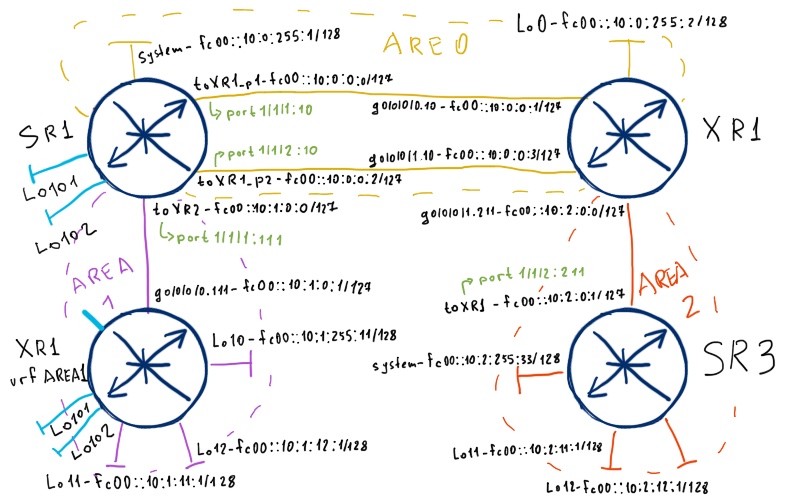
The actual redistribution will be the following:
| Device | Prefix | External type |
| SR1 | 2001:DB8:1:1::/64 | E1, Metric 100 |
| SR1 | 2001:DB8:1:2::/64 | E2, Metric 50 |
| AREA1 | 2001:DB8:11:1::/64 | N1, Metric 1100 |
| AREA1 | 2001:DB8:11:2::/64 | N2, Metric 1050 |
In addition to the configuration above we’ll limit redistribution at SR1 so that redistributed IPv6 prefix won’t be injected into Area 1. If not to do it, prefixes 2001:db8:1:1::/64 and 2001:db8:1:2::/64 will be redistributed into area 0.0.0.1 as NSSA routes as SR1 has interface in area 0.0.0.1 as well the configuration what we should use:
| Nokia (Alcatel-Lucent) VSR (SR 7750) | Cisco IOS XR (ASR 9000) |
| SR1 | AREA1 (VRF at XR1) |
|
A:SR1>config>router>policy-options# info |
RP/0/0/CPU0:XR1(config)#show conf |
Don’t remember to explicitly activate ASBR functionality in Nokia (Alcatel-Lucent) SR OS.
Let’s check NSSA external LSA in LSDB at AREA1:
|
RP/0/0/CPU0:XR1#show ospfv3 AREA1 vrf AREA1 database nssa-external Type-7 AS External Link States (Area 0.0.0.1) LS age: 297 LS age: 297 |
As we have configured, there is no other external (or more precisely NSSA external) LSAs in its LSDB. Pay attention to the “Forwarding Address” (FA) field, as it has some non-zero value. Cisco IOS XR chose it as the highest active loopback interface number (Lo12 in our case. Each router then makes routing lookup to this address before installing route in RIB.
When there is redistribution in NSSA, FA is always set non-zero value.
Let’s take a look into LSDB at SR1:
|
A:SR1# show router ospf3 database | match expression “NSSA|Ext|Type|-|=” |
You see 2 LSA7 generated by AREA1 (RID 10.1.255.11), which are then translated into LSA5 by this Nokia (Alcatel-Lucent) VSR (SR 7750). Pay attention that after translation the Link State ID is changed:
|
A:SR1# show router ospf3 database type nssa 0.0.0.2 detail |
Basically it’s normal behavior for Nokia (Alcatel-Lucent) SR OS and for Cisco IOS XR to preserve the forwarding address. In the same time the forwarding address for routes redistributed into normal area will be zero (in Nokia (Alcatel-Lucent) SR OS you even don’t see this field):
|
A:SR1# show router ospf3 database type external 0.0.0.2 detail |
There is one exception to this rule, though it isn’t widely used. First links in google for “forwarding address ospf external” will help you.
At SR3 we don’t see any external routes as we have totally stub area there:
|
A:SR3# show router route-table ipv6 |
But at XR1 we see all these external IPv6 prefixes:
|
RP/0/0/CPU0:XR1#show route ipv6 ospf |
We have almost finished with establishing the connectivity between all our subnets. You remember that area between AREA1 (VRF at XR1) and SR1 is NSSA so it doesn’t have any default route by default. Also we have limited the redistribution of routes at SR1 into area 0.0.0.1, so we need somehow to configure injection of default route at SR1. There are two options basically: convert configuration at SR1 from NSSA to totally NSSA or inject default route as LSA7. Let’s use the latter option:
| Nokia (Alcatel-Lucent) VSR (SR 7750) |
| SR1 |
|
A:SR1>config>router>ospf3# info |
If you omit “type-nssa” in Nokia (Alcatel-Lucent) SR OS the route will be injected as LSA3 without converting area to totally NSSA. Cisco IOS XR by default injects default route into NSSA as LSA7.
Now the LSDP at AREA1 must changed, so it makes sense to check it:
|
RP/0/0/CPU0:XR1#show ospfv3 AREA1 vrf AREA1 database |
Looks good, isn’t it?
Default route in the backbone area
What I haven’t covered in the previous article is the injecting of the default route in the core. Though this topic is relatively easy, I’d provide brief configuration here. There are two possible options, which depend on presence of default route in the RIB. One option demands is, whereas another doesn’t. So let’s configure the second one both at Nokia (Alcatel-Lucent) VSR (SR 7750) and Cisco IOS XR (ASR 9000):
| Nokia (Alcatel-Lucent) VSR (SR 7750) | Cisco IOS XR (ASR 9000) |
| SR1 | XR1 |
|
RP/0/0/CPU0:XR1(config)#show conf |
Configuration at SR1 is empty, isn’t it? The reason for that is the absence of such feature in Nokia (Alcatel-Lucent) SR OS. Nevertheless Cisco IOS XR (and other Cisco IOS) has such function. Upon applying this command, Cisco IOS XR generates LSA5 with default route and distributes it across the whole OSPF domain:
|
A:SR1# show router ospf3 routes |
In the same time this route isn’t installed (even as black hole) in XR1’s RIB:
|
RP/0/0/CPU0:XR1#sh route ipv6 ospf ::/0 |
To redistribute default route in Nokia (Alcatel-Lucent) SR OS you have to have in routing table and then use export route-policy (as other external routes redistribution).
Removal of IPv6 addresses at routers interconnects
Upon analyzing routing table you can point out those next hops for IPv6 prefixes are always IPv6 link-local addresses. As I have already said before, usually you can omit IPv6 global unicast addresses from links that connect routers with each other, as they just waste the routing table. Actually you can don’t configure them only on these links, as you must configure them at customer-facing interfaces and at loopbacks. The topology will look like then as follows:
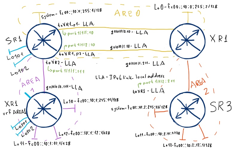
There is no any single change in the OSPFv3 configuration either at Nokia (Alcatel-Lucent) VSR (SR 7750) or Cisco IOS XRv (ASR 9000). What we do is just removal of IPv6 global unicast addresses at the following links:
- 2x SR1 – XR1
- SR1 – AREA1
- XR1 – SR3
We won’t notice the change in the routing table as we have already configured prefix summarization between areas and in each area we have only two routers, so all interconnect prefix are already installed in routing table as local routes. Nevertheless the information in intra-area prefix LSA will be reduced. At the example below you see output at Cisco XR1 of LSA generated by Nokia (Alcatel-Lucent) SR1:
| Before | After |
|
RP/0/0/CPU0:XR1#show ospfv3 XR1 database prefix adv-router 10.0.255.1 Intra Area Prefix Link States (Area 0.0.0.0) Routing Bit Set on this LSA Routing Bit Set on this LSA |
RP/0/0/CPU0:XR1#show ospfv3 XR1 database prefix adv-router 10.0.255.1 Intra Area Prefix Link States (Area 0.0.0.0) Routing Bit Set on this LSA Routing Bit Set on this LSA |
To prove that everything works well, let’s check whether we have full connectivity between all system/loopback interfaces of all devices.
From the far right Nokia (Alcatel-Lucent) VSR (SR 7750), which is SR3, we have the following results:
|
A:SR3# ping fc00::10:1:255:11 count 1 A:SR3# ping fc00::10:1:11:1 count 1 A:SR3# ping fc00::10:1:12:1 count 1 A:SR3# ping 2001:db8:11:1::1 count 1 A:SR3# ping 2001:db8:11:2::1 count 1 A:SR3# ping fc00::10:0:255:1 count 1 A:SR3# ping 2001:db8:1:1::1 count 1 A:SR3# ping 2001:db8:1:2::1 count 1 A:SR3# ping fc00::10:0:255:2 count 1 |
SR3 has the full connectivity to all the necessary IPv6 prefixes. Let’s check now the far left Cisco IOS XR router (AREA1 – VRF at XR1):
|
RP/0/0/CPU0:XR1#ping vrf AREA1 fc00::10:0:255:1 source fc00::10:1:255:11 RP/0/0/CPU0:XR1#ping vrf AREA1 2001:db8:1:1::1 source fc00::10:1:255:11 RP/0/0/CPU0:XR1#ping vrf AREA1 2001:db8:1:2::1 source fc00::10:1:255:11 RP/0/0/CPU0:XR1#ping vrf AREA1 fc00::10:0:255:2 source fc00::10:1:255:11 RP/0/0/CPU0:XR1#ping vrf AREA1 fc00::10:2:255:33 source fc00::10:1:255:11 |
As you can see our networks works well. If you want to compare it with your configuration or just test something, use final configs for references:
SR1_final XR1+AREA1_initial SR3_final
Lessons learned
As you can see, with the follow of my series I discover not only Nokia (Alcatel-Lucent) SR OS configuration and its interoperability with Cisco IOS XR, but many other things, like optimizing lab and so on as well. For example, building of the topology for current lab give me insight how to build topology for Service Architecture exam, which I going to pass this week.
Conclusion
So far we have covered the configuration of IPv4/OPSFv2 and IPv6/OSPFv3. These protocols (or this protocol) are one of the most popular and widely deployed routing protocols not only in the Service Provider networks, but in enterprises as well. I hope that now you have understanding how you can implement it in multivendor environment and therefore you are better prepared for real tasks. In my opinion the interoperability will be one of the most important horse forces in the networks in future, as more and more clients are implementing at least dual vendor strategy. Take care and good bye!
Support us
BR,
Anton Karneliuk





In OSPFv3 Link LSAs, in opposite to other area- and domain-wide scope LSAs, are held in interface data structure. Hence, they could be displayed in SR-OS via “show router ospf3 interface database”.
Hi Alexander,
Thanks for your valuable comment, I was not aware of it. I’ll update the article with the correspond information.
BR,
Anton