

Hello my friend,
In this article I’ll step aside from traditional approach, where I describe configuration only of Cisco IOS XR and Nokia (Alcatel-Lucent) SR OS. As we have fully virtual lab, we have to take into consideration how VLANs are trunked in Linux. It’s crucial not only for our lab, but also for SDN environment, where different NFVs are connected using VLANs and pass through the production traffic (i.E. from VLAN X to VLAN Y).
Such configuration of trunk sub interface in Nokia (Alcatel-Lucent) SR OS is also applicable for real routers like SR 7750. For Cisco it’s also relevant: just the same configuration you have in any IOS XR devices (ASR 9000, CRS 1/3, NCS 6000 and so on).
Simple but hidden
This is very strange thing that it’s really hard to find information how to configure subinterfaces at Nokia (Alcatel-Lucent) VSR (SR 7750) router. With the Cisco IOS XR (also IOS, IOS XE and NX-OS) there is no such problem. Just enter in Google “Cisco router trunk” and the first link leads you to necessary information. But with Nokia (Alcatel-Lucent) SR OS, it’s really difficult. Actually I haven’t found, just figured out that from the console myself.
Also I find that fact quite weird that in Cisco courses it’s described hot con configure VLAN trunks at switches and routers even in CCNA (the most basic course). What’s about Nokia (Alcatel-Lucent), I’ve reviewed the guide for NRS I (the most basic course) and found that overall explanation of VLANs (even QinQ concept), but there is no even simple example of how to configure them. Probably there is such reason for such absence of information. But I don’t know it, so I want to disclose with you my findings.
Physical and logical topologies
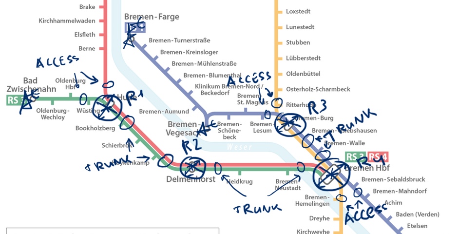
First of all let’s review the physical topology of our lab. That’s necessary, because we need to have clear understanding, where we will configure trunks.

If this article is the first one that you are reading from my series or you have just forgotten how to build the lab, take a look at the first article. The logical topology for current lab will be the following:
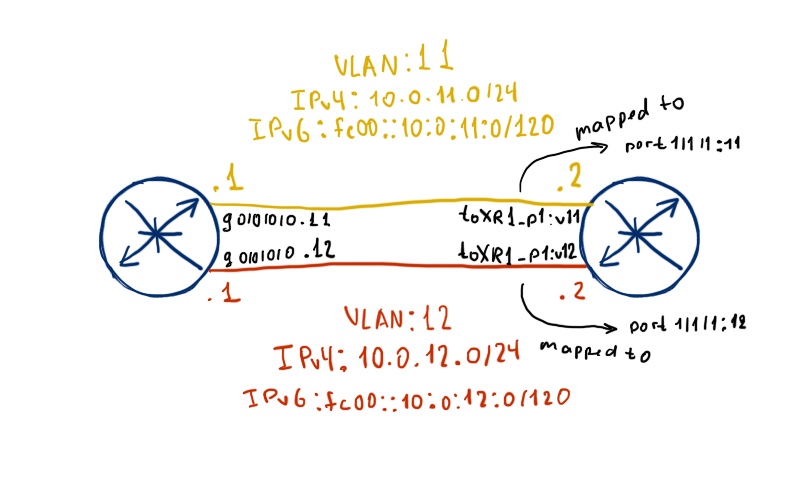
In this lab we don’t care about loopback or system interface (for Nokia(Alcatel-Lucent) VSR (SR 7750)), because my goal here is to explain you how to configure dot1q (IEEE 802.1Q) subinterfaces and test their operation.
Configuration of 802.1Q sub interfaces in Cisco IOS XR
From my prospective it’s the easiest part, that’s why I will start from explanation of Cisco’s configuration. Probably I consider this part as the easiest one, but as you will see just a couple of lines below, it’s really easy.
There are only two differences in configuration between usual interfaces (what we have reviewed previously) and sub interface:
- You configure sub interface number in interface’s number.
- You configure VLAN number, which sub interface uses .
Let’s take a look into CLI of Cisco IOS XR:
| Cisco IOS XR untagged interface | Cisco IOS XR 802.1Q subinterface |
|
interface GigabitEthernet0/0/0/0 |
interface GigabitEthernet0/0/0/0.11 |
With bold I’ve marked the differences. The general guidelines are to have subinterface’s number equal to VLAN number, but it’s not obligation. You can have “interface GigabitEthernet0/0/0/0.16” with “encapsulation dot1q 5” and it will work perfectly well. Such guidelines were made to simplify operation of Cisco routers. Here some consideration about subinteface and interface:
- It’s OK to have parent interface and subintefaces configured together. In this case parent interface process all untagged (without VLAN tag) packets, whereas subinterface process packets related to configured VLAN.
- The subinterface is fully independent logical interface, so from IPv4/IPv6 point of view all subinterfaces and parent interface are independent.
- The parent interface and child subinterfaces share the same MAC address.
- If you shutdown the child subinterface, only it will be out of opetaion.
- If you shutdown the parent interface, it and all child subinterfaces will be out of operation.
To clarify the first point, take a look at the following output:
|
RP/0/0/CPU0:XR1# show run |
As you can see, it’s really easy to configure sub interface in Cisco IOS XR (and all other IOS versions). Let’s go to the peering router.
Configuration of 802.1Q sub interfaces in Nokia (Alcatel-Lucent) SR OS
Frankly speaking the configuration of dot1q sub interfaces at Nokia (Alcatel-Lucent) VSR (SR 7750) is also very easy. In the first article in my series I’ve briefly mentioned that there is strict decoupling of physical port configuration (and operation as well) and logical interface. There are also some differences in configuration between usual port and tagged one:
| Nokia (Alctel-Lucent) SR OS untagged | Nokia (Alctel-Lucent) SR OS 802.1Q tag |
|
A:SR3# admin display-config |
A:SR3# admin display-config |
The first difference is that we need to change the encapsulation type of the port, where we want to configure subinterfaces. By default it’s configured as “encap-type null”, what means that interface accept untagged packets.
You can change encapsulation type only on interface that is out of operation. So you have to shut down the interface before you’ll change its encapsulation.
The next step is to change appropriate VLAN under logical interface configuration by issuing “port 1/1/1:X” command, where is “X” is VLAN number, which will be associated with this subinterface. It’s really easy, isn’t it? I don’t know, why such simple and really essential configuration for networking is hidden in Nokia (Alcatel-Lucent) VSR (SR 7750) documentation. Let’s verify our configuration:
|
A:SR3>config>port# show router interface detail | match expression “If|Id” |
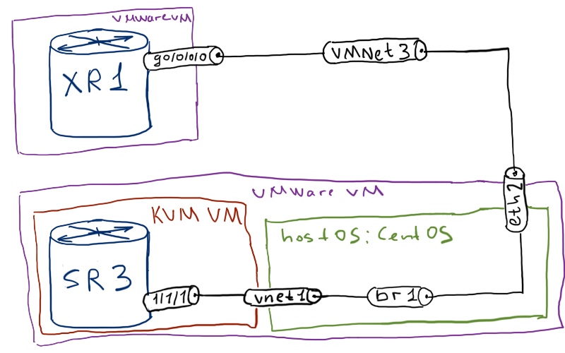
If we were connecting physical devices, for example Nokia (Alcatel-Lucent) SR 7750 to Cisco ASR 9000 or Cisco NCS 6000, then we would finish our task. But right now we had to configure trunking of VLANs in Linux, as it connects Cisco IOS XRv to Nokia (Alcatel-Lucent) VSR.
Configuration of 802.1Q sub interfaces in Linux
When I started to write this article I was unaware that I should take care of VLANs in Linux. I just made the configuration, which I described above, but nothing worked. I was mistaken, so I had to dig into that problem deeply. Fortunately I find very good configuration example in Internet, which I tried to use in my lab and it had helped a lot. But before configuring, let’s review the logic of bridging in Linux:
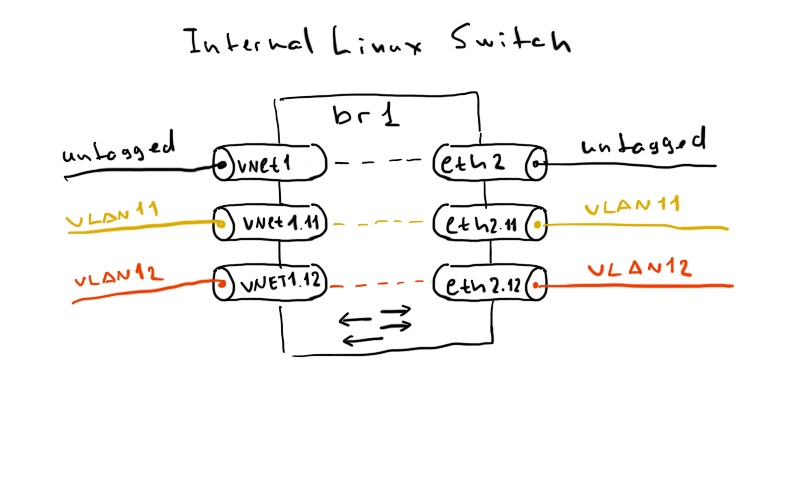
Let’s analyze together this diagram with the physical topology in the beginning. Interface “eth2” of our Linux switch “br1” is attached to external virtual network “VMnet3”, which attach Linux VM with Nokia (Alcatel-Lucent) to Cisco IOS XRv. Another interface “vnet1” of the switch “br1” is attached to Nokia (Alcatel-Lucent) VSR. By default this switch passes only untagged traffic. Actually the same logic we have into Cisco switches (I don’t have hands-on experience with Nokia (Alcatel-Lucent) ESS switches, so I can’t tell about them): we have configure VLANs and add them to proper ports in order to pass certain 802.1Q tagged traffic through the switch. Linux bridging follows the same logic. First of all let’s review, at which interface we should allow VLANs:
|
[root@localhost ~]# brctl show br1 |
Then following the example in the article below, let’s configure the necessary VLANs, and activate them:
|
[root@localhost ~]# modprobe 8021q |
Briefly check the status of newly created interface and add them to the bridge:
|
[root@localhost ~]# ifconfig | grep “eth2\|vnet1” |
Everything is configured, let’s verify which interface we do have attached to out Linux switch:
|
[root@localhost ~]# brctl show br1 |
Testing
Now it’s time to test how our trunkig is working (and if it’s working in overall).
|
A:SR3# ping 172.16.11.2 |
It works fine. Let’s test another sub interface from Cisco side
|
RP/0/0/CPU0:XR1#ping 172.16.12.1 |
But IPv6 for another sub interface doesn’t work, because we see the following log into Cisco CLI:
|
RP/0/0/CPU0:XR1#RP/0/0/CPU0:Jul 17 14:17:56.420 : ipv6_nd[277]: %IP-IPV6_ND-3-ADDRESS_DUPLICATE : Duplicate address fe80::250:56ff:fe34:2a3d has been detected on GigabitEthernet0/0/0/0.12 |
Interestingly, but in Nokia (Alcatel-Lucent) we doesn’t see any logs about such problems. The reason for this problem (and it good that it has happened) is combination of two factors:
- When the new IPv6 device starts to operate, it should send the ICMPv6 ND packet to check, whether someone has already same link-local address (so called Duplicate Address Detection – DAD function). If there is such address, the new one doesn’t start to operate to prevent loss of traffic.
- Linux switch actually doesn’t separate VLANs. It just strips the 802.1Q tag, when it receives the packet, and add it, when it sends it further.
To fix this problem we can change the IPv6 link-local address at Cisco IOS XR side, as it’s possible to configure it manually:
|
RP/0/0/CPU0:XR1(config-subif)#show conf |
Now both IPv4 and IPv6 connections between Nokia (Alcatel-Lucent) VSR and Cisco IOS XRv are fully workable:
|
RP/0/0/CPU0:XR1#ping fc00::172:16:11:1 |
Let’s review IPv6 neighbor table in Nokia (Alcatel-Lucent) SR OS:
|
A:SR3# show router neighbor |
Lessons learned
It’s very hard to describe solely one part of the configuration in real world. I don’t want to simplify it to the student’s guide level, because I will start to deceive you then. Discovering of 802.1Q trunking in virtual environment covered also some IPv6 connectivity problems, caused by operation’s specifics of Linux switch. I’m personally happy about that fact, because I’ve learned something new (I hope, you also).
Conclusion
Trunking of VLANs is essential technology for each modern network. It’s not possible to overestimate its importance, so I think that my article helps you to configure trunks between Cisco IOS XR and Nokia (Alcatel-Lucent) VSR (SR 7750) devices. Trunking has being used for decades already and it will be used further certainly.
Support us
BR,
Anton Karneliuk