Hello my friend,
Today we’ll review implementation of the most advanced, scalable, flexible (and the most complex) L2VPN that exists today in networking world. It’s called EVPN (Ethernet VPN). Let’s take a look what is it and how to configure it in mixed Nokia (Alcatel-Lucent) SR OS and Cisco IOS XR environment.
You can find detailed explanation of EVPN operation in book “MPLS in the SDN Era”. There also some good documents created by Nokia and Cisco.
Brief overview
You can think about EVPN as about advanced version of VPLS, though it’s completely different technology with different rules that solves the same task that is multipoint L2VPN. There are several advantages that significantly differs EVPN from VPLS. Here are two the most important from my point of view:
- MAC learning. In EVPN MAC learning is done via BGP (control-plane MAC learning), whereas in VPLS MAC learning is done by looking into source MAC address in Ethernet frame (data-plane MAC learning). The first option is much scalable and quicker in terms of convergence, what perfectly matches need of virtual machines (VMs) migration inside data center or between them.
- L2/L3 traffic. In EVPN you can configure the same IP and MAC addresses at all PE routers therefore you don’t need any FHRP (like HSRP or VRRP) in order to implement redundancy for VMs inside VPLS. For VMs themselves it means that ARP cache will be valid after VM migration to another location with another PE router.
There are more advantages, but even solely these two differences makes EVPN perfect solution for data-centers and data center interconnects. If we speaking about Service Provider world, then EVPN can be used in the same areas, where VPLS is used. But Cisco IOS XR doesn’t support pure EVPN, unfortunately. In Cisco world only NX-OS (platform used for Cisco Nexus Switches) supports pure EVPN. So what we can do? We can implement PBB-EVPN then, which is supported both by Nokia (Alcatel-Lucent) SR OS and Cisco IOS XR.
PBB (provider backbone bridging) is another L2VPN technology that is called also MAC-in-MAC (802.1ah) encapsulation, because PEs add additional Ethernet header with its own MAC addresses as source and peering PE as destination. It uses concept of I-SID for customer’s demultiplexion, what has the same meaning as VLAN tag in 802.1Q frame. The main advantage of PBB over dot1Q or Q-in-Q is that in PBB the customer MAC addresses are hidden from service provider (SP) core network, therefore less resources are used and more scalability in SP network is achieved. Moreover it’s absolutely OK to transport Q-in-Q traffic over PBB so you can provide the most flexible L2 services for your clients.
The overall architecture of PBB-EVPN over MPLS looks as follows:
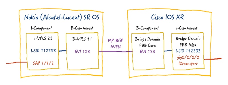
The main differences between PBB-EVPN and “ordinary” EVPN is that in PBB-EVPN BGP is used for MAC learning of Provider’s MAC addresses (B-Component), whereas Customer’s MAC addresses (I-Component) use data plane MAC learning.
What are we going to test?
EVPN in general is control-plane (or signaling) technology that may use different type of transport. One of the most popular for data-center is VXLAN, and both Nokia (Alcatel-Lucent) SR OS and Cisco IOS XR supports it. Unfortunately Cisco IOS XRv (at least my version 5.3.2) doesn’t support it, that’s we’ll test only PBB-EVPN with MPLS forwarding plane. If later Cisco IOS XRv will support VXLAN, we’ll such kind of lab separately.
Topology
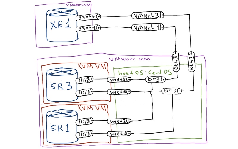
Physical topology:
The logical topology remains as it was previously in VPWS and VPLS lab:
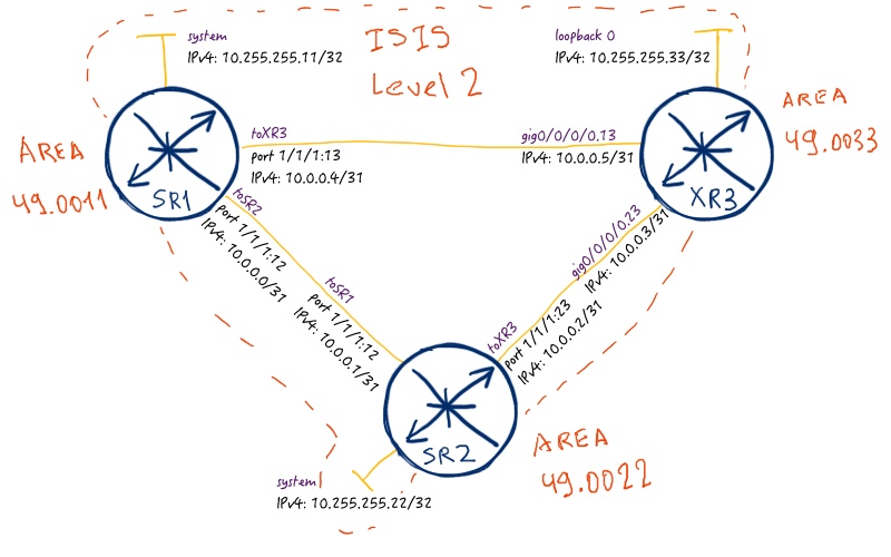
In previous articles about MPLS L2VPNs we have used different types of MPLS forwarding plane. So for VPWS we have used RSVP-TE for creation of MPLS LSP, whereas in VPLS we have used SPRING (Segment Routing). In this article we’ll use LDP for establishing MPLS LSPs. Routing protocol will be ISIS as it was previously.
Unfortunately Cisco IOS XRv doesn’t support data plane for L2 services, so we can test packet forwarding via PBB-EBPN only between SR1 and SR2 (XR3 can be P router in this case), though SR3 fully participates in signaling.
Initial configuration for the lab is in the following files: linux_initial sr1_initial sr2_initial xr3_initial
I recommend you to review VPLS configuration beforehand, as vpls configuration context is used for PBB and EVPN in Nokia (Alcatel-Lucent) SR OS
PBB-EVPN over MPLS configuration
All routers in our network can be PE for PBB-EVPN, so we configure all of them with corresponding PBB and EVPN components.
In order for PBB to get working, I-SID must be the same across PBB customer-facing instances. In order EVPN to get working, EVI must be the same.
Here is out service topology:
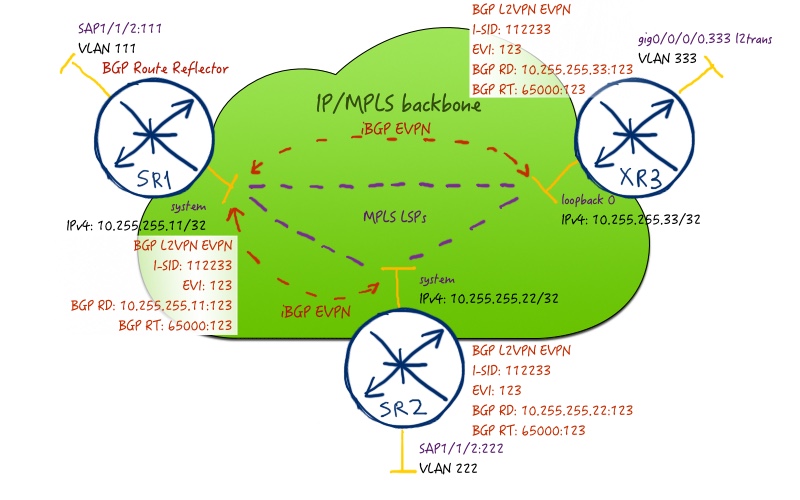
Let’s configure PBB-EVPN in our multi-vendor network build with Nokia (Alcatel-Lucent) VSR (SR 7750) and Cisco IOS XRv (ASR 9000):
| Nokia (Alcatel-Lucent) VSR (SR 7750) | Cisco IOS XR (ASR 9000) |
| SR1 | XR1 |
|
A:SR1>edit-cfg# candidate view |
RP/0/0/CPU0:XR3(config)#show conf |
| SR2 | |
|
A:SR2>edit-cfg# candidate view |
I’m pretty sure that you have a question “What is going on here?” This question is fully legitimate, because it isn’t easy to understand configuration at a glance.
First of all we configure BGP peering in address-family EVPN (AFI/SAFI 25/70) between our PEs. SR1 acts as BGP route-reflector, so you see command “cluster” there. As the source interfaces for BGP session, system interface (at Nokia (Alcatel-Lucent) SR OS) and loopback 0 (at Cisco IOS XR) is used in order to make connection stable and ease next-hop lookup further, when we will map MPLS LSPs to services.
The second crucial part is configuration of “B-component” of PBB, what stands for “backbone”. In Nokia (Alcatel-Lucent) SR OS you add keyword “b-vpls” upon VPLS service creation, whereas in Cisco IOS XR you configure it as “pbb core” inside of bridge-domain configuration context. Inside this “B-component” you add mapping to certain EVI. In Cisco IOS XR it’s enough, but in Nokia (Alcatel-Lucent) SR OS you have to add parameters of forwarding plane. As we use MPLS as forwarding plane for our PBB-VPLS, we add resolution to any MPLS technology. You can see that there is a significant difference comparing to VPWS/VPLS configuration, where we had to configure and map SDP to service. In PBB-EVPN we have an option to map service directly to MPLS LSP. The main reason for that, what comes to my mind, is that in SDP we have a mix of MPLS LSP and signaling information. In case of PBB-EVPN we have only BGP for signaling (like in MPLS L3 VPNs), so there is no necessity co to have SDP.
The third (and the last) part of our configuration is “I-component” of PBB, what stands for “Instance”. That is customer-facing entity, so here we configure physical interface that is used for termination of customer circuit. In Nokia (Alcatel-Lucent) SR OS we have to add keyword “i-vpls” upon creation of VPLS service. Inside the configuration context we configure mapping to B-component and I-SID to uniquely identify this particular L2VPN in IP/MPLS network.
MP-BGP parameters for EVPN (like route-distinguisher (RD) and route-targets (RTs)) are configured automatically based on EVI, AS number and router-id.
That’s it. I hope that after the provided explanation, you understand more or less the configuration. Now it’s time to see what happens in the different FIB/LFIB and other tables and make some packet capture.
In multihoming scenarios it’s necessary to configure general EVPN parameters, like ES (Ethernet-Segment) for attached circuits, but it isn’t relevant for our lab. Refer to official config guides for more information about this topic.
The first notification regarding PBB-EVPN establishment you get in logs, if they are activated:
|
SR OS: |
This notification informs you that you BGP session in L2VPN/EVPN address-family is established successfully. The next step is to check what BGP routes are sent/received. Let’s check them in Cisco IOS XR, because we see all routers of all types just on the one page:
|
RP/0/0/CPU0:XR3#show bgp l2vpn evpn rd 10.255.255.33:123 |
I’ve filtered routes by RD in order to shorten the output, because each PE send its own routes with its own RD, which are then imported according to RT in appropriate table. You see that there are two types of routes in our table: 2 and 3. The route type 3 is used for transporting BUM traffic (Broadcast, Unknown Unicast, Multicast), whereas the type 2 is used for sending known unicast traffic. In Nokia (Acatel-Lucent) SR OS you see these routes separately:
|
A:SR1# show router bgp routes evpn inclusive-mcast |
As you may guess, each route has its own label that is used for transporting certain packets. And if the labels for unicast traffic is shown at once, labels for BUM traffic isn’t shown. To see them you need to go into details:
|
A:SR1# show router bgp routes evpn inclusive-mcast detail | match expression “Nexthop|Label|Tunnel|Tag” |
The next interesting fact, which you can spot reviewing the provided outputs, is that Nokia (Acatel-Lucent) SR OS uses the same label both for BUM and known unicast traffic, whereas Cisco IOS XR uses two separate labels. Also you can notice that Nokia (Alcatel-Lucent) SR OS announces routes for configured I-SID (112233) and for default (0), whereas Cisco IOS XR announces route only for configured I-SID (112233).
Let’s review the configuration of the bridges (VPLS instances) to see what is going there. We start with the B-Component:
|
A:SR1# show service service-using |
There isn’t too much information that is useful for us, is it? Just point out that service-MTU in B-component must be at least 18 bytes bigger than I-Component. The most relevant information is contained in bgp-evpn section:
|
A:SR1# show service id 11 bgp-evpn |
Pay attention that control word is disabled. It’s very important and you will see further why. To check associated I-Components with your B-Component, use the following command:
|
A:SR1# show service id 11 i-vpls |
Ok, let’s check the I-Component itself:
|
A:SR1# show service id 22 base |
As MAC addresses of B-components are already distributed via BGP, we can check FDB (forwarding database) for it. In the same time we haven’t configured so far any customers for our PBB-EVPN service, so FDB in I-Component must be empty:
|
A:SR1# show service id 11 fdb detail |
Let’s check Cisco side now. The main disadvantage of using Cisco IOS XRv is the absence of data plane for L2 services, therefore we can’t make any tests of its operation. The only thing that we can do is to check control plane of PBB-EVPN. Just right after configuration part we have checked the BPG RIB for L2VPN/EVPN routes. Let’s check the bridges themselves now:
|
RP/0/0/CPU0:XR3#show l2vpn bridge-domain |
Here you see the brief summary of all configured bridges. To see EVPN parameters of the B-Component in Cisco IOS XR you should display detailed information (the output is modified to leave only interesting information):
|
RP/0/0/CPU0:XR3#show l2vpn bridge-domain bd-name CORE_PART detail |
Information about I-Component is shown but the same command, just change the bridge name:
|
RP/0/0/CPU0:XR3#show l2vpn bridge-domain bd-name EDGE_PART detail |
So far we have reviewed some fancy outputs of different “show” commands that informs us about status of configured service (mainly signaling). Now it’s time to make some kind of simulation to see what happens with packet in our network. We’ll use the same topology to what we have used previously in VPLS lab:
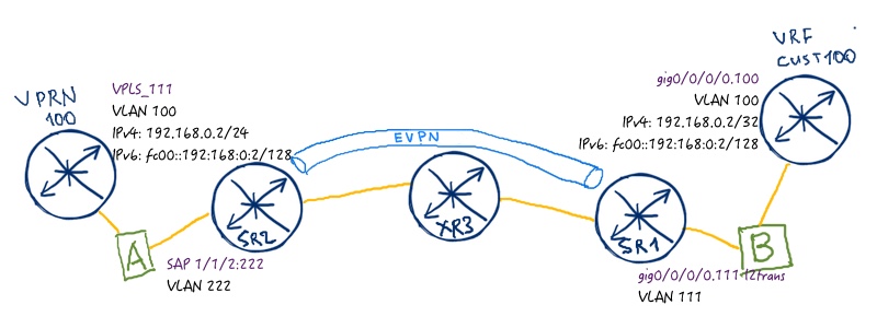
Don’t forget to disable direct link between SR1 and SR2. Now let’s configure our customers’ simulation:
| Nokia (Alcatel-Lucent) VSR (SR 7750) | Cisco IOS XR (ASR 9000) |
| SR1 | XR1 |
|
A:SR1>edit-cfg# candidate view |
RP/0/0/CPU0:XR3(config)#show conf |
| Linux – bridge A | Linux – bridge B |
|
[root@localhost ~]# |
[root@localhost ~]# |
Before we make ping, we check again the content of I-VPLS instances at SR1 and SR2:
|
A:SR1# show service id 22 fdb detail |
Now it’s time to make some pings:
|
A:SR1# ping router 100 192.168.0.2 |
Our PBB-EVPN works! It’s wonderful, isn’t it? Let’s check what is going on the backstage. The first packet is ARP, because our customer need to resolve MAC address to construct proper ICMP packet. Wireshark shows it:

Unfortunately Wireshark doesn’t decode the packet properly, but still we see some information:
- “20” – unlabeled ARP come to SR2 from VPRN 100 at SR1
- “21” and “22” – SR2 add labels and send ARP (that is BUM traffic) to SR1 and XR3. You see it from MPLS labels.
- “23” – XR3 swaps transport label and sends packet “21) further to SR1.
- “24” – SR2 send unlabeled packet to VRF CUST100 at XR3
- “25 – 28” back way of the packet from VRF CUST100 at XR3 to VPRN 100 at SR1. This traffic is sent as unicast one.
After ARP process is finished, ICMP itself comes:

During this process the MAC addresses are learned and filled in I-Component’s FDB, so we can check it’s operation:
|
A:SR1# show service id 22 fdb detail |
In the same there is no changes in B-Components, as PE MAC addresses were initially discovered via BGP and all signaling was formed. That’s it with PBB-EVPN over MPLS. The final configs are here: linux_final sr1_final sr2_final xr3_final
Lessons learned
You see that unlabeled packets are displayed correctly, whereas packets send over PBB-EVPN aren’t clearly decoded. Let’s see, probably we can do it better. Here is the packet:
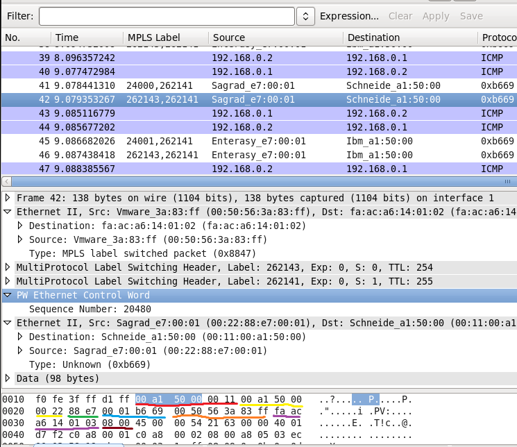
The problem is that Wireshark thinks that our labeled has control world, though it doesn’t have it.
This problem is well known and discussed in this thread at wireshark site.
Here what we have:
- “00 a1 50 00 00 11” (marked with red) is PBB MAC address of the SR1 that is destination MAC address in this case. You can check it with what we have configured.
- “00 a1 50 00 00 22” (marked with yellow) is PBB MAC address of SR2 that is source MAC address in this case.
- “88 e7” (marked with green) is EtherType for PBB.
- “00 01 b6 69” (marked with blue) is hexadecimal representation of I-SID, which is 112233.
- “00 50 56 3a 83 ff” (marked with orange) is MAC address of the interface in VRF CUST100 at XR3 that is destination MAC address for customer traffic:
|
RP/0/0/CPU0:XR3#show int gig 0/0/0/0.100 | inc add |
- “fa ac a6 14 01 03” (marked with violet) is MAC address of the interface in VPRN 100 at SR1 that is source MAC address for customer traffic:
|
A:SR1# show router 100 interface “VPLS111_CUST” detail | match MAC |
- “08 00” (marked with brown) is EtherType for IPv4 that is encapsulated further.
Conclusion
EVPN-PBB, as I’ve already stated in the beginning, is probably the most scalable and powerful L2VPN technology that can be deployed into MPLS word of service providers. Pure EVPN with VXLAN data plane is perfect solution for data centers and their interconnections. Nokia (Alcatel-Lucent) SR OS supports both PBB-EVPN and pure EVPN, whereas Cisco IOS XR currently supports only PBB-EVPN (pure EVPN is supported at Cisco NX-OS).
So far we have reviewed all possible option of deploying L2VPN services across Service Provider network: VPWS, VPLS and EVPN. In the next article we’ll review L3VPN (BGP/MPLS VPN). Take care and good bye!
Support us
BR,
Anton Karneliuk





Great article!
I’m trying to setup EVPN between Nokia 7750 and Cisco ASR9000 routers in MPLS, but my efforts is not as successful as yours. When I enable EVPN for the BGP neighbor, the BGP peer between Nokia and Cisco goes down. I got the follow error message on Nokia: “Update Msg Err (Invalid Network Field)”.
Do you know how to solve this?
Hi Lars,
Thanks for your feedback. Could you share config part and version of TiMOS, IOS XR?
BR,
Anton
Thanks for you reply. TiMOS version is 14.0R4 and IOS XR version 5.1.0. The IOS XR version is bit old, so I’ll try to upgrade that one first.
Hi Lars,
Basically if you configure “family evpn” at Nokia SR OS side and “address-family l2vpn evpn” at Cisco it should work, so I can assume that there is a particular bug with interoperability. I’ve seen such problems with other technologies. Please, let me know, whether update fixes your problem.
BR,
Anton
There seem to have been a bug in IOS-XR 5.1.0. Upgrading to 5.3.4 resolved the interoperability problem with Nokia 7750.
Hello,
Interesting your opinion, PBB-EVPN on IOS XR with MC-LAG work together?
I received some results and now thinking. This is network design problem or bug in IOS XR. The scheme is couple PE reachable each other via route-reflector.
Hi Alexandr,
It should work, at least Cisco states so. Unfortunately I don’t have two boxes like ASR9000 or NCS 5000 to test it, but as far as I saw in Cisco Live presentation, it should be working.
BR,
Anton
Hello,
On IOS XR, PBB-EVPN requires “singleton” mode under redundancy iccp group configuration. Legacy MC-LAG requires statically configured member under redundancy iccp group. These settings are mutually exclusive. It is hard situation for migration from L2VPN to PBB-EVPN.
Hi Alexandr,
Thanks for the comment. That’s quite valuable information.
BR,
Anton
Hi Anton,
I have configured evpn-mpls in vpls service. Its working fine. When I enable spoke-sdp to make vpls and evpn-mpls to work simultaneously , spoke-sdp goes down, with route evpn conflict .
How to make evpn and vpls to work together ?
Hi Karthik,
Could you provide more details for configuration or logs? If you use BGP for signaling, there is different AFI/SAFi for VPLS and EVPN. But there is something called EVI and associated with interface, so it might influence.
BR,
Anton
Hi Anton!
Really nice article! It has cleared a few confusions coming from martini and Kompella, (and i think it also also added lots of new questions the process 😛 ). A colleague and I have been overall debating the various ways of deploying L2 services on nokia closely following the MEF guidelines for Eline and ELan. We a now exploring purely bgp evpn and some questions arise when dealing with PtP offerings EPL and EVPL. I normally see spoke-sdp configurations which e are trying to stay away from just purely to not mix&match methods. I see you normally refer to EVPN as a way to solve Multipoint solutions, in your experience how does it behave with EPL and EVPL? In articular EVPL poses some questions as you would like to handle C-tags, Mac learning and presevation of CoS p-bits. I have been trying to dig for an official nokia guide showing the various MEF offerings based on the different methods, particularly EVPN and PBB-EVPN, but no luck!
Hi Juan,
Thanks for kind feedback! FOr sure you can use EVPN to address all L2VPN topics. My assumtion is that it wouldn’t be any difference on configuration. In the same way you can use VPLS to provide p2p services, it’s just the matter of used resources on the router.
BR,
Anton