Hello my friend,
Recently we’ve reviewed, how to establish point-to-point L2 connectivity over MPLS network (VPWS). Now it is turn of multipoint L2 services that is called VPLS (Virtual Private LAN Service). Let’s learn how you configure it in the network built with Nokia (Alcatel-Lucent) SR OS and Cisco IOS XR.
Disclaimer
For more theory about VPLS architecture and operation refer I advise you to refer to “Nokia Service Architecture SRC course” and book “MPLS in the SDN Era”.
Brief overview
You can think about VPLS as a ordinary Ethernet switch. So there are two main difference between VPLS and VPWS besides multipoint functionality:
- MAC address learning;
- split-horizon rule.
If you think a bit, both of these rules are caused by multipoint nature of VPLS. It would be possible to implement both MAC address learning and split-horizon in VPWS, but there is no sense to do it as traffic can be forwarded only to another PE.
MAC address learning in VPLS associates unicast MAC address with pseudowires (PWs) or attached interfaces in order to reduces unnecessary flooding just in the same manner as Ethernet switch does. Split-horizon rule implies that traffic from pseudowire isn’t sent to MPLS cloud (other pseudowires) back. In certain cases you would like to relax this rule, if you are building concept that is called hierarchical VPLS (H-VPLS).
What are we going to test?
In VPWS we have configured two possible options of signaling: LDP and BGP (including BGP auto-discovery). Just the same options we have in VPLS as well, so we’ll configure LDP-based and BGP-based VPLS. VPLS with LDP signaling is described in RFC 4762 and BGP signaling is described in RFC 4761. There is also one informational RFC for all BGP-based L2 MPLS VPNs that is RFC 6624.
Topology
Physical topology for our lab doesn’t change:
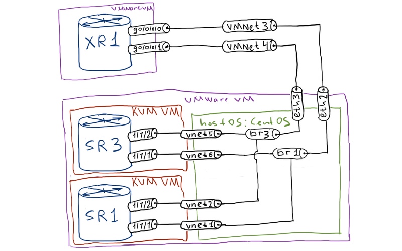
The logical topology for the current lab is just the same as it was in the previous one for VPWS:
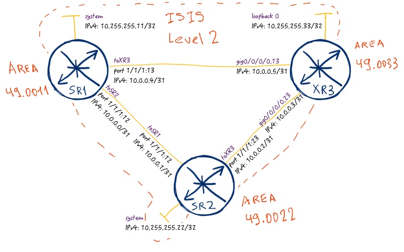
In the current topology we are still using ISIS as our routing protocol (IGP). MPLS forwarding plane in this article is built using SPRING (Segment Routing), so we testing the most recent technology in real cases. As VPLS is multipoint topology, all our routers will be PE, so we’ll configure VPLS instances at each router.
Unfortunately Cisco IOS XRv doesn’t support data plane for L2 services, so we can test VPLS only between SR1 and SR2 (XR3 can be P router in this case).
Initial configuration for the lab is in the following files:
Refer to the article about VPWS to get understanding about MPLS service framework in Nokia (Alcatel-Lucent) SR OS and Cisco IOS XR.
LDP-based VPLS
Let’s start with VPLS option, which uses LDP for signaling. It doesn’t support auto-discovery, like BGP-based VPLS does, so addition of each new site to VPLS requires reconfiguration of all sites. On the other hand, configuration itself is easier, as you strictly configures VC-IDs. Here is the topology of our service:
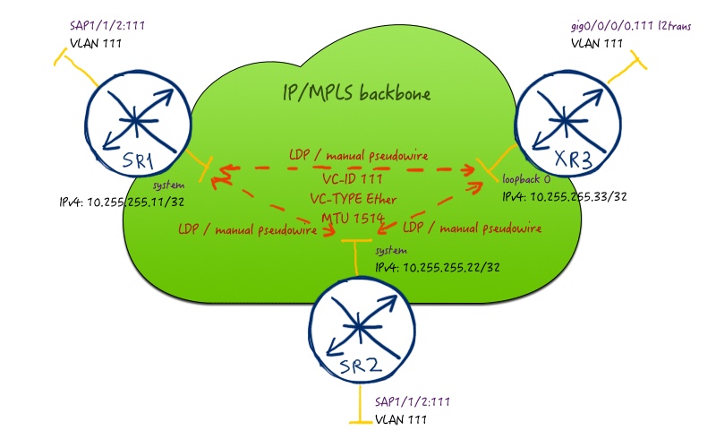
In order for VPLS to get into operation, VC-ID, VC-TYPE and MTU must match across all configured neighbors.
As we use all our routers as PE, so we configure all of them for new instance:
| Nokia (Alcatel-Lucent) VSR (SR 7750) | Cisco IOS XR (ASR 9000) |
| SR1 | XR1 |
|
A:SR1>edit-cfg# candidate view |
RP/0/0/CPU0:XR3(config)#show conf |
| SR2 | |
|
A:SR2>edit-cfg# candidate view |
In Nokia (Alcatel-Lucent) SR OS we configure first of all SDPs and map them to SPRING (Segment Routing) MPLS LSPs. Point out that we have to increase path-mtu manually at SDP level, though in the production network you must avoid it. The reason for that is check performed by Nokia (Alcatel-Lucent) SR OS regarding different MTUs. See the in the detailed explanation in lessons learned. There are also two particular things regarding VPLS configuration itself. First, “vpls id” must match VC-ID for LDP session, it’s possible to change this behavior but it’s better to follow it as best practice. Second, you configure “mesh-sdp” (rather than “spoke-sdp” as we did in VPWS, because “mesh-sdp” implement split-horizon rule.
In Cisco IOS XR we configure customer interface as “l2transport” to put it into switching mode. The VPLS service is configured into “bridge-domain VPLS_LDP” context, where “VPLS_LDP’ is arbitrary name. Pay attention that you configure LDP neighbors with corresponding VC-ID (or PW-ID in Cisco terminology) under VFI (virtual forwarding instance) context.
In Cisco IOS XR you don’t need to map VPLS to any MPLS transport LSP, as done automatically via next hop lookup in FIB/LFIB
Actually VFI in Cisco IOS XR does just the same, what “mesh-sdp” does in Nokia (Alcatel-Lucent) SR OS; it implements split-horizon rule. You can configure “spoke-sdp” in VPLS in SR OS, when you build H-VPLS. Just in the same way you can configure LDP neighbor in bridge-domain (VPLS instance) without VFI for H-VPLS in IOS XR.
Well, let’s see what we have in outputs of show commands. Before we go into details of checking the configuration of any MPLS service, we should check if we have established MPLS LSP to corresponding PE:
|
A:SR1# show router tunnel-table |
For more information about SPING (Segment Routing) operation and configuration refer to this article.
Ok, we see that we have all LSPs configured and working. Pay attention that you have tunnels both from SPRING and from SDP configuration. Now it is turn to review all configured services to define interesting one:
|
A:SR1# show service service-using |
Up to now only one VPLS is configured (besides two default services), so it’s easy to find it. Let’s review operational status of the VPLS components:
|
A:SR1# show service id 111 base |
Here you see useful information like Service MTU, associated SAP/SDP and their operational status. To display the detailed parameters of SDP use the following command:
|
A:SR1# show service id 111 sdp 33:111 detail |
A lot of output is similar to the once, we saw in the VPWS. What is different is SDP type that is set to “Mesh”. Also you can see that LSP Id associated with this SDP is 524292, what corresponds to SR-ISIS LSP, which you have seen in the first show output in this article. As LDP is signaling protocol for this type of VPLS, information about peers VC-ID, VC-TYPE and MTU, as well as MPLS service label, you can found in LIB:
|
A:SR1# show router ldp binding service service-id 111 detail |
For VPLS we are able to configure Ethernet type of pseudowire, therefore we save 4 bytes on dot1q tag. In VPWS we haven’t achieved such option in interoperable scenario.
All of the most important parameters of VPLS we have reviewed from Nokia (Alcatel-Lucent) SR OS prospective. Let’s check Cisco IOS XR side.
We are starting with checking LFIB:
|
RP/0/0/CPU0:XR3#show mpls forwarding |
The first two entries relate to SPRING (Segment Routing). As we see that there are some bytes switched, it means that SPRING MPLS LSPs are up and running. Let’s check or L2VPN services:
|
RP/0/0/CPU0:XR3#show l2vpn bridge-domain brief |
We see that service seems to work correctly (at least signaling). It doesn’t only seem, it’s really so, but due to absence of data plane for L2 switching in Cisco IOS XR we can’t check it. Detail evaluation of the VPLS parameters is long and boring, so I’m providing only the most interesting part:
|
RP/0/0/CPU0:XR3#show l2vpn bridge-domain bd-name VPLS_LDP detail |
In Nokia (Alcatel-Lucent) SR OS we can see the parameters of MAC learning in FDB (forwarding data base) that is associated with VPLS:
|
A:SR1# show service id 111 fdb |
We can test VPLS between SR1 and SR2, as Nokia (Alcatel-Lucent) VSR supports all features that real SR 7750 devices including MPLS L2 services. We’ll temporary disable direct connection between SR1 and SR2 in order to make traffic pass XR3 as a transit node. As emulation of customer devices, I’ll create VPRN 100 at SR1 and VRF CUST100 at XR3. Linux bridge performs function of dot1q tag rewrite in order traffic with appropriate tag comes to VPLS. So our test topology looks like as follows:
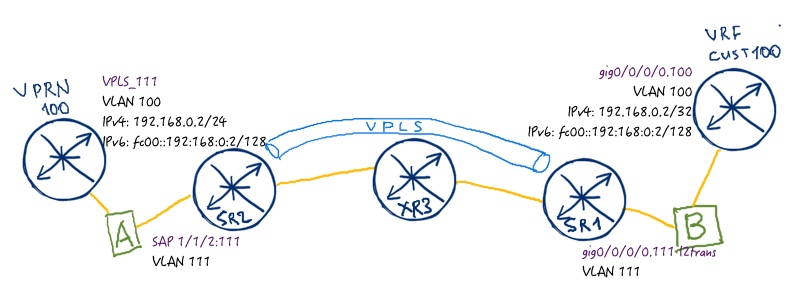
The configuration for our devices looks as follows:
| Nokia (Alcatel-Lucent) VSR (SR 7750) | Cisco IOS XR (ASR 9000) |
| SR1 | XR1 |
|
A:SR1>edit-cfg# candidate view |
RP/0/0/CPU0:XR3(config)#show conf |
| Linux – bridge A | Linux – bridge B |
|
[root@localhost ~]# |
[root@localhost ~]# |
Let’s ping Site B of the Customer A (VRF CUST100 at XR3) from Site A (VPRN 100 at SR1) and make a dump in Wireshark:
|
A:SR1# ping router 100 192.168.0.2 count 1 |
MAC learning phase is omitted in order to save the space. Refer to sources mentioned in the beginning.
Traffic dump from Wireshark show the journey of our packet across MPLS network:

The first four steps form forward path (VPRN_100) à (SR2) à (XR3) à (SR1) à (VRF_CUST100):
- Unlabeled packet comes from VPRN_100 at SR2.
- SR2 pushes MPLS service label associated egress PE for this service (262140), then it pushes MPLS transport label from SPRING (16011).
|
A:SR2# show router ldp bindings services service-id 111 detail | match expression “Lbl|Peer” |
- XR3 swaps MPLS transport label (16011 à 500011) without touching service label that remains the same (262140).
|
RP/0/0/CPU0:XR3#show mpls forwarding | include “16011|Label” |
- SR1 pops MPLS transport label (500011) as it is tail-end for this MPLS LSP, then it pops service label (262140) and sends packet from the appropriate interface to VRF_CUST100.
The backward path follows the very same logic.
For VPLS operation the FDB, how is it called in Nokia (Alcatel-Lucent) SR OS, is one of the most important database, because there is located mapping of all MAC address to interfaces or pseudowires:
|
A:SR2# show service id 111 fdb detail |
In Cisco IOS XR we can’t show the same table because there is no L2 data plane in Cisco IOS XR. What about IPv6? Let’s test how this traffic is transported over VPLS:
|
A PING fc00::192:168:0:2 56 data bytes |
And here is the actual packet flow:

As you can imaging, there is no difference for VPLS between IPv4 and IPv6 traffic, as we transit layer 2 frames including Ethernet header, where Ethertype for IPv4/IPv6 is encoded.
Before we go to the next VPLS option, we bring back link between SR1 and SR2.
BGP-based VPLS
This type of VPLS provides you ease of scale and signaling in your network, because you don’t need to change configuration of existing VPLS peers when adding new PE. On the other hand you have to tune BGP in order to get satisfactory speed of convergence. Here is the service topology that we are going to configure:
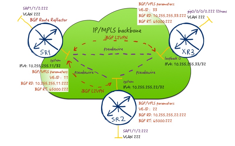
In order to remove full-mesh of iBGP sessions, we configure SR1 as BGP route reflector. The address family is the same, as it was in BGP-based VPWS – L2VPN (AFI/SAFI 25/65). We use 65000:222 as route-target for this VPN in order to distribute the VPLS information. So, let’s perform the necessary configuration:
| Nokia (Alcatel-Lucent) VSR (SR 7750) | Cisco IOS XR (ASR 9000) |
| SR1 | XR1 |
|
A:SR1>edit-cfg# candidate view |
RP/0/0/CPU0:XR3(config)#show conf |
| SR2 | |
|
A:SR2>edit-cfg# candidate view |
In Nokia (Alcatel-Lucent) SR OS first of all we establish BGP neighbors with other PEs in corresponding address-family (remember that SR1 is BGP route reflector). Then we have to create new set of SDPs, which are mapped to newly created SDP-group “SDP_BGP_AUTO”. We need new SDPs, because new type of signaling (BGP instead of LDP) is used. SDP-group is used in order to map SDPs to BGP discovered next-hops via PW-template. PW-template is also used for enabling control-word. The VPLS service itself has a number of important component that is BGP specific, but the first one VPN-ID must be configured at the time of VPLS-service creation. It must be the same across all PE involved in this VPLS (the same is true for BGP route-targets). The last important element for BGP signaling is VE-ID. It works in the same way as in VPWS and must be unique inside VPLS cloud.
In Cisco IOS XR you do approximately the same configuration with the exception of new SDP, as there is no SDPs in Cisco. MPLS LSPs are completely separated from services, that’s why mapping service to MPLS LSP is done solely by next-hop lookup in routing table.
Also pay attention that we have changed service MTU in Nokia (Alcatel-Lucent) SR OS. Service MTU handling is different for BGP and for LDP at Cisco IOS XR
Let’s start our checks with BGP peering:
|
A:SR1# show router bgp summary |
We see that peering is established in the proper address family. Let’s check the summary parameters of this BGP-based VPLS:
|
A:SR2# show service id 222 base |
You see that SDP VC-IDs are automatically configured for BGP-derived pseudowires. Nevertheless we see that all of them are up and running. Let’s check the details for SDP that leads to XR3:
|
A:SR2# show service id 222 sdp 3 detail |
We see service labels that are used for this pseudowire and mapping of the VPLS to actual MPLS LSP. Again we have VC-TYPE “Ether” that means that we transport Ethernet frame without tag over MPLS. You see that signaling type is BGP. If you forgot (or don’t know) which type of signaling and/or MPLS LSP is used for SDP, you can check by the following command:
|
A:SR2# show service sdp |
BGP parameters of our local VPLS entity helps you by troubleshooting to understand what route-targets are send/received and what is our VE-ID:
|
A:SR2# show service id 222 bgp |
Signaling information from other PEs is available in BGP RIB. Here is the example of one route:
|
A:SR2# show router bgp routes l2-vpn rd 10.255.255.11:222 detail |
Let’s check Cisco IOS XR side. The first step is to check BGP peering for L2VPN:
|
RP/0/0/CPU0:XR3#show bgp l2vpn vpls summary |
As peering is established and works well, we can go the next step in reviewing the operation of BGP-based VPLS. What about label blocks, which are used for service labels?
|
RP/0/0/CPU0:XR3#show l2vpn discovery |
As you can, here we have three main parameters for each session: label base, VE-ID (Edge ID) and offset. When we use BGP-based VPLS, BGP doesn’t signal each particular label. It signals mentioned parameters, so that each router calculates label itself. As all routers use the same algorithm, calculated labels match across all routers. At the following output you see summary parameters of configured VPLS:
|
RP/0/0/CPU0:XR3#show l2vpn bridge-domain brief |
The most interesting part for us here is BGP-signaled pseudowired, so I provide only configuration of one of the. For more information about attached circuit (local interface) and other parameters refer to the LDP part:
|
RP/0/0/CPU0:XR3#show l2vpn bridge-domain bd-name VPLS_BGP detail |
Information about other PEs you can find in BGP RIB. You can spot that route is encoded as “VE-ID:Offset”:
|
RP/0/0/CPU0:XR3#show bgp l2vpn vpls rd 10.255.255.33:222 |
Pay attention that here you see not the actual label but rather the label base. In the previous output there was actual label. The detailed information is transferred in community (actually, extended community) field:
|
RP/0/0/CPU0:XR3#show bgp l2vpn vpls rd 10.255.255.33:222 11:9/32 | inc comm |
Everybody likes lab testing and verification, whereas the best type of verification is to ping or traceroute something. I like it as well, so let’s make small test that is similar to one we’ve done in the end of LDP part. Let’s create new VPRN 101 at SR1 and attach it to SR2 VPLS instance, whereas new VRF CUST101 at XR3 will be attached to SR1 VPLS instance. The direct link between SR1 and SR2 is temporary disabled in order to make traffic pass XR3. The topology for the simulation is the following:
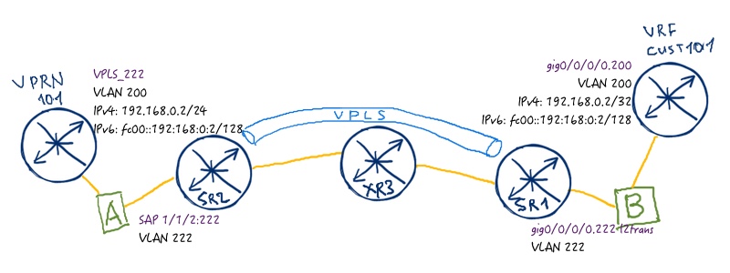
The configuration is very simple and repeats what we have done in LDP part (besides VLAN numbers). Pay attention that IPv4 and IPv6 addresses are the same:
| Nokia (Alcatel-Lucent) VSR (SR 7750) | Cisco IOS XR (ASR 9000) |
| SR1 | XR1 |
|
A:SR1>edit-cfg# candidate view |
RP/0/0/CPU0:XR3(config)#show conf |
| Linux – bridge A | Linux – bridge B |
|
[root@localhost ~]# |
[root@localhost ~]# |
Now it’s ping time:
|
*A:SR1# ping router 101 192.168.0.2 count 1 |
Wireshark shows how our brave ICMP packet travels from VPRN 101 to VRF CUST101 and back:

For the sake of consistency, let’s test IPv6 transmission as well:
|
*A:SR1# ping router 101 fc00::192:168:0:2 count 1 |
Wireshark shows the same picture, as expected:

The final configs are here:
Lessons learned
Service MTU limits the frame size that is encapsulated in MPLS. Its value is is 1514 bytes by default in Nokia (Alcatel-Lucent) SR OS. Adding 4 bytes for control word we get 1518 bytes MTU, and this value must be lower or equal than SDP path-MTU. SDP path-MTU is calculated automatically from network-port MTU including all possible encapsulation. As we have 1518 bytes MTU at network port, the effective SDP path-MTU is 1492 bytes (1518 – 14 Eth header – 4 dot1Q header – 4 MPLS transport label – 4 bytes MPLS service label). There are two options what we can do (excluding change of network-port MTU):
- Change SDP path-MTU to be equal or higher than service MTU.
- Change service MTU to be equal or lower than SDP path-MTU.
The second option leads to necessity of MTU change at Cisco IOS XR side as well. So the service MTU at Nokia (Alcatel-Lucent) SR OS side will be 1488 and at Cisco IOS XT side will be 1474.
Check this article to understand differences in MTU handling in Nokia (Alcatel-Lucent) SR OS and Cisco IOS XR.
Then Cisco IOS XR performs automatic check if service MTU equals customer port MTU that is 1500 by default (and we haven’t changed it). If it isn’t equal, then VPLS is down. In our case we can’t change port MTU, as core-facing and customer-facing sub interfaces are configured on the same physical port, so we are getting into recursive loop.
If we change SDP path-MTU, we adjust it to service MTU without impacting anything else. But all the frames bigger than 1488 bytes (including Ethernet header) will be silently dropped.
MTU is one of the trickiest thing, when we are speaking about network communication in general and VPN services in particular.
Conclusion
VPLS is one of the most widely deployed technology for tunneling Ethernet packets across MPLS network. It’s often used not only in Service Provider networks for backhauling of different services in RAN (Radio Access Network) or connecting customers in Metro Access, but also in big data center networks or for data center interconnects (DCI). Building VPLS in multi-vendor network with Nokia (Alcatel-Lucent) SR OS and Cisco IOS XR is possible due to RFC nature of this technology. So far we have reviewed two the most widely used L2VPN services in MPLS network: VPWS and VPLS. In the next article we’ll speak about the newest one that is called EVPN (Ethernet VPN). Take care and good bye!
Support us
BR,
Anton Karneliuk




Hello Thanks for the wonderful article. Don’t you need spoke-sdp’s configured under VPLS.
I was not able to see the SDP’s attached to the services until spoke SDP’s are configured.
Hello Nani,
in BGP-based VPLS you bind it not directly to SDP but to PW-template, which looks for established SDP and map it BGP information.
BR,
Anton
Hi Anton, What does Legend: pp = Partially Programmed mean?
Thanks
i tried to do interop between Nokia and Cisco, Whenever i put sap into VPLS service on NOKIA side, my sdp-binding gets removed . If i removed sap, SDP-bindings come back up. Do you have any idea what could be possible reason ?